Chapter 10 Sinusoidal Steady State Power Calculations In









- Slides: 28
Chapter 10 Sinusoidal Steady- State Power Calculations In Chapter 9 , we calculated the steady state voltages and currents in electric circuits driven by sinusoidal sources We used phasor method to find the steady state voltages and currents In this chapter, we consider power in such circuits The techniques we develop are useful for analyzing many of the electric devices we encounter daily, because sinusoidal sources are predominate means of providing electric power in our homes, school and businesses Examples Electric Heater which transform electric energy to thermal energy Electric Stove and oven Toasters Iron Electric water heater And many others
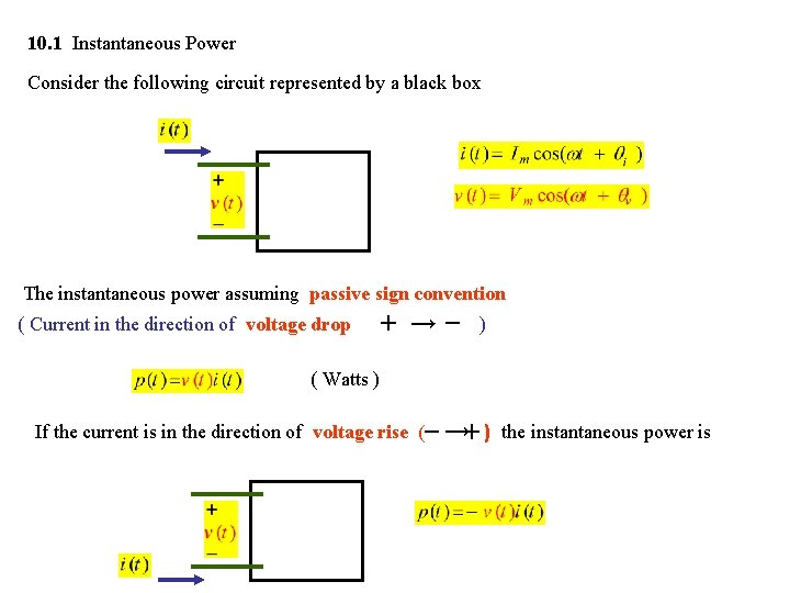
10. 1 Instantaneous Power Consider the following circuit represented by a black box The instantaneous power assuming passive sign convention ( Current in the direction of voltage drop + →- ) ( Watts ) If the current is in the direction of voltage rise (- →+ ) the instantaneous power is
Since Therefore Since
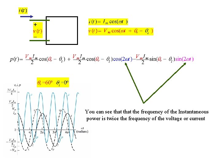
You can see that the frequency of the Instantaneous power is twice the frequency of the voltage or current
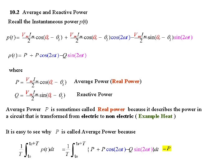
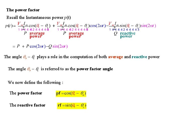
10. 2 Average and Reactive Power Recall the Instantaneous power p(t) where Average Power (Real Power) Reactive Power Average Power P is sometimes called Real power because it describes the power in a circuit that is transformed from electric to non electric ( Example Heat ) It is easy to see why P is called Average Power because
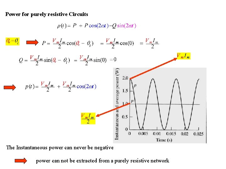
Power for purely resistive Circuits The Instantaneous power can never be negative power can not be extracted from a purely resistive network
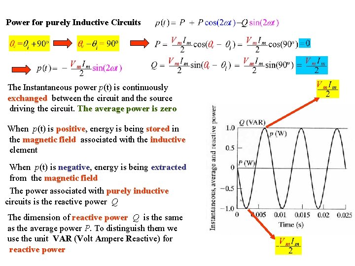
Power for purely Inductive Circuits The Instantaneous power p(t) is continuously exchanged between the circuit and the source driving the circuit. The average power is zero When p(t) is positive, energy is being stored in the magnetic field associated with the inductive element When p(t) is negative, energy is being extracted from the magnetic field The power associated with purely inductive circuits is the reactive power Q The dimension of reactive power Q is the same as the average power P. To distinguish them we use the unit VAR (Volt Ampere Reactive) for reactive power
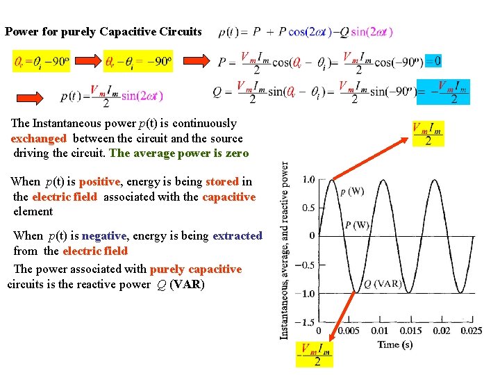
Power for purely Capacitive Circuits The Instantaneous power p(t) is continuously exchanged between the circuit and the source driving the circuit. The average power is zero When p(t) is positive, energy is being stored in the electric field associated with the capacitive element When p(t) is negative, energy is being extracted from the electric field The power associated with purely capacitive circuits is the reactive power Q (VAR)
The power factor Recall the Instantaneous power p(t) The angle v - i plays a role in the computation of both average and reactive power The angle v - i is referred to as the power factor angle We now define the following : The power factor The reactive factor
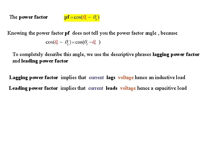
The power factor Knowing the power factor pf does not tell you the power factor angle , because To completely describe this angle, we use the descriptive phrases lagging power factor and leading power factor Lagging power factor implies that current lags voltage hence an inductive load Leading power factor implies that current leads voltage hence a capacitive load
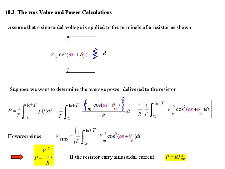
10. 3 The rms Value and Power Calculations Assume that a sinusoidal voltage is applied to the terminals of a resistor as shown Suppose we want to determine the average power delivered to the resistor However since If the resistor carry sinusoidal current
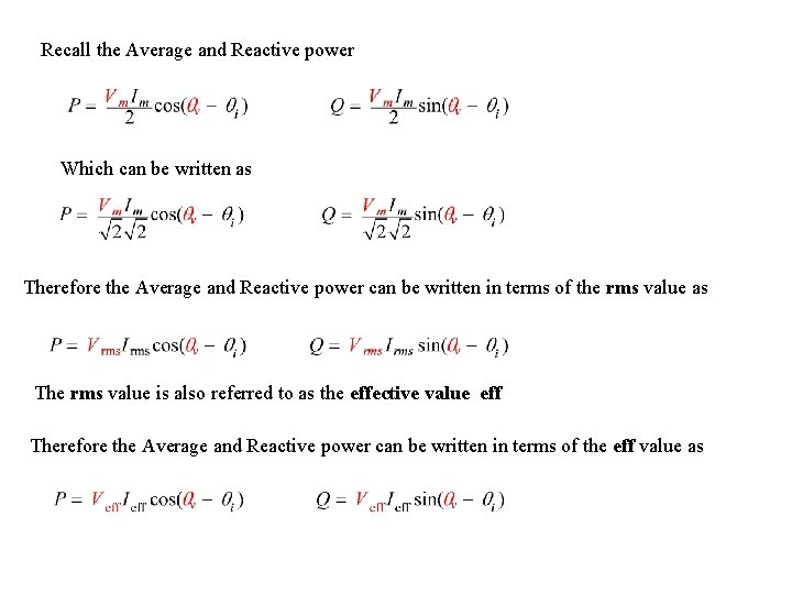
Recall the Average and Reactive power Which can be written as Therefore the Average and Reactive power can be written in terms of the rms value as The rms value is also referred to as the effective value eff Therefore the Average and Reactive power can be written in terms of the eff value as
Example 10. 3
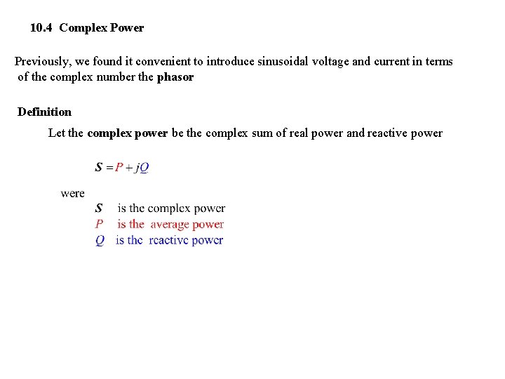
10. 4 Complex Power Previously, we found it convenient to introduce sinusoidal voltage and current in terms of the complex number the phasor Definition Let the complex power be the complex sum of real power and reactive power
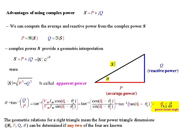
Advantages of using complex power - We can compute the average and reactive power from the complex power S - complex power S provide a geometric interpretation were The geometric relations for a right triangle mean the four power triangle dimensions (|S|, P, Q, ) can be determined if any two of the four are known
Example 10. 4
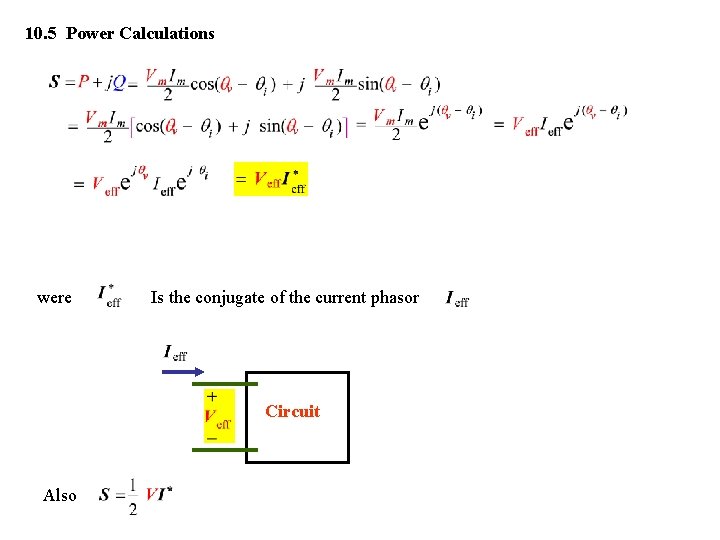
10. 5 Power Calculations were Is the conjugate of the current phasor Circuit Also
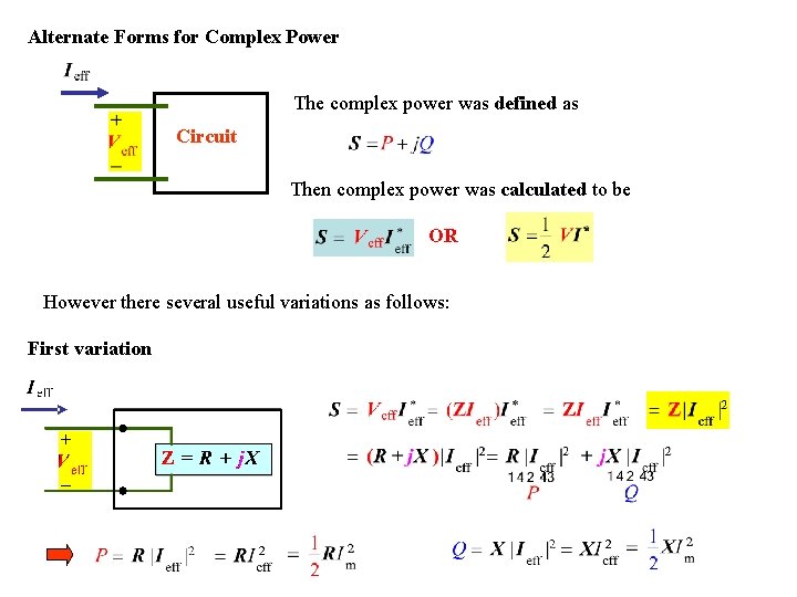
Alternate Forms for Complex Power The complex power was defined as Circuit Then complex power was calculated to be OR However there several useful variations as follows: First variation
Second variation If Z = R (pure resistive) X= 0 If Z = X (pure reactive) R= 0
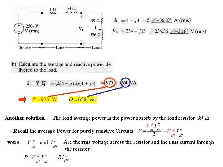
Example 10. 5 Line Load rms because the voltage is given in terms of rms
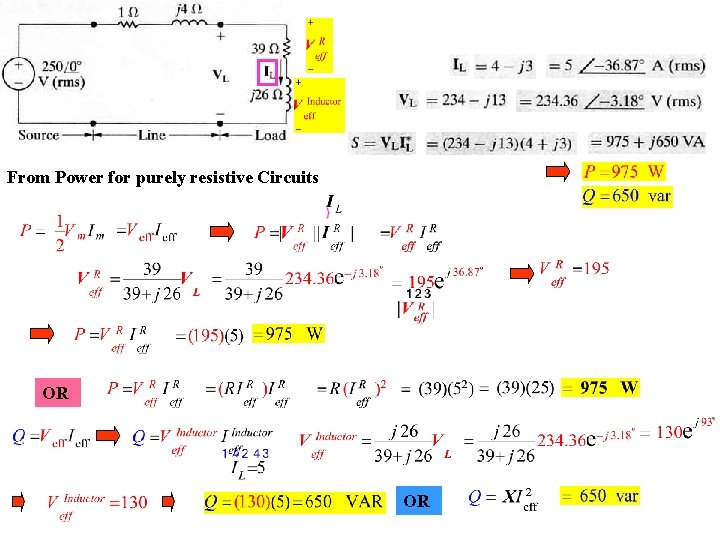
Another solution The load average power is the power absorb by the load resistor 39 W Recall the average Power for purely resistive Circuits were Are the rms voltage across the resistor and the rms current through the resistor
From Power for purely resistive Circuits OR OR
Line OR using complex power OR
Line OR Load
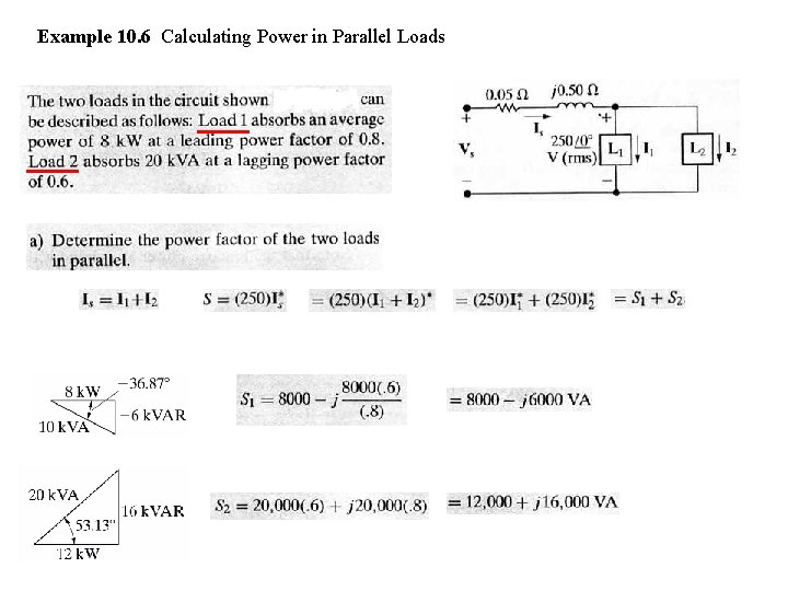
Example 10. 6 Calculating Power in Parallel Loads
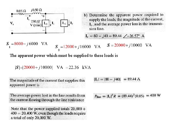
The apparent power which must be supplied to these loads is