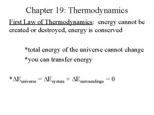
First Law of Thermodynamics applied to Flow processes


- Slides: 26

First Law of Thermodynamics applied to Flow processes

Control Volume & Control Surface A control volume is a certain fixed region on which attention is focused and through which the moving substance flows. A control surface is the surface on the control volume.

Steady flow process Ø The flow is said to be steady if the rate at which the fluid flows through a machine or piece of apparatus and the rate at which the energy changes are constant. Ø At the steady state of a system, any thermodynamic property will have a fixed value at a particular location, and will not alter with time. These thermodynamic property depends only on space coordinates but not on time.

Assumptions made in the analysis of steady flow process of a system 1) The mass flow through the system remains constant. 2) Fluid is uniform in composition. 3) The only interaction between the system and its surroundings are work and heat. 4) The state of fluid at any point remains constant with time. 5) In the analysis, only potential, kinetic and flow energies are considered.

Simple steady flow process of a system The two governing equations are: 1) Mass balance equation, and 2) Energy balance equation

Notations

Mass balance equation By the conservation of mass, if there is no accumulation of mass within the control volume, the mass flow rate entering the system must be equal to the mass flow rate leaving the system. i. e. , mass flow rate entering = mass flow rate leaving This equation is known as Mass balance equation (or) Continuity equation

Work transfers in steady flow processes ØIn the flow process, the work transfer may be an external work (or) a flow work. ØThe external work refers to all the work transfer across the control surface other than that due to normal fluid forces. ØThe only external work transfers considered in engineering thermodynamics are shear work (shaft or stirring) and electrical work.

Energy balance equation Since there is no accumulation of energy, by the conservation of energy, the total rate of flow of all energy streams entering the control volume must be equal to the total rate of flow of all energy streams leaving the control volume. i. e. Total energy flow rate entering = Total energy flow rate leaving (or) Considering unit mass of the substance, This equation is known as Energy balance equation (or) Steady Flow Energy Equation (SFEE)

Applications of First law applied to flow processes 1) 2) 3) 4) 5) 6) 7) 8) 9) 10) Nozzle Diffuser Compressor Turbine Throttling device Boiler Evaporator Condenser Water turbine Water pump

Nozzle / Diffuser Nozzle Diffuser

Compressor (or)

Turbine (or)

Throttling device

Throttling curve (or) isenthalpic curve on T-P plane

Boiler

Evaporator

Condenser

Water Turbine since

Water Pump

Problem - 1 Air flows steadily at the rate of 0. 5 kg/s through an air compressor, entering at 7 m/s, 100 k. Pa pressure and 0. 95 m 3/kg volume, and leaving at 5 m/s, 700 k. Pa pressure and 0. 19 m 3/kg volume. The internal energy of the air leaving is 90 k. J/kg greater than that of air entering. Cooling water in the compressor jackets absorbs heat from the air at the rate of 58 k. W. (a) Compute the rate of shaft work input to the air in k. W. (b) Find the ratio of the inlet and outlet pipe diameters.

Problem - 2 In a steam power station, steam flows steadily through a 0. 2 m diameter pipeline from the boiler to the turbine. At the boiler end, the steam conditions are found to be: p = 4 MPa, t = 400 C, h = 3213. 6 k. J/kg and v = 0. 95 m 3/kg. At the turbine end, the conditions are found to be: p = 3. 5 MPa, t = 392 C, h = 3202. 6 k. J/kg and v = 0. 084 m 3/kg. There is a heat loss of 8. 5 k. J/kg from the pipeline. Calculate the steam flow rate.

Problem - 3 Air at a temperature of 15 C passes through a heat exchanger at a velocity of 30 m/s where its temperature is raised to 800 C. It then enters a turbine with the same velocity of 30 m/s and expands until the temperature falls to 650 C. On leaving the turbine, the air is taken at a velocity of 60 m/s to a nozzle where it expands until the temperature has fallen to 500 C. If the air flow rate is 2 kg/s, calculate (a) the rate of heat transfer to the air in the heat exchanger, (b) the power output from the turbine assuming no heat loss, and (c) the velocity at the exit of the nozzle, assuming no heat loss. Take the enthalpy of the air as h=cpt, where cp is the specific heat equal to 1. 005 k. J/kg and t is the temperature.

Problem - 4 In a gas turbine the gas enters at the rate of 5 kg/s with a velocity of 50 m/s and enthalpy of 900 k. J/kg and leaves the turbine with a velocity of 150 m/s and enthalpy of 400 k. J/kg. The loss of heat from the gases to the surroundings is 25 k. J/kg. Assume for gas R = 0. 285 k. J/kg-K and cp=1. 004 k. J/kg-K and the inlet conditions to be at 100 k. Pa and 27 C. Determine the power output of the turbine and the diameter of the inlet pipe.

Problem - 5 12 kg/min of air is delivered by a centrifugal compressor. The inlet and outlet conditions are C 1 = 12 m/s, p 1 = 1 bar, v 1 = 0. 5 m 3/kg and C 2 = 90 m/s, p 2 = 8 bar, v 2 = 0. 14 m 3/kg. The increase in the enthalpy of air passing through the compressor is 150 k. J/kg and heat loss to the surroundings is 700 k. J/min. Find (a) motor power required to drive the compressor, and (b) ratio of inlet to outlet pipe diameters. Assume that inlet and discharge lines are at the same level.

is minimum when (or) Therefore maximum work obtainable is equal to
 In a flow process the work transfer may be of which type
 First law of thermodynamics equation open system
 First law of thermodynamics
 Brayton cycle process
 Joule's first law of thermodynamics
 Internal energy in thermodynamics definition
 First law of thermodynamics sign convention
 First law of thermodynamics control mass
 First law of thermodynamics
 Thermodynamics of ideal gases
 Newton's first law and second law and third law
 Newton's first law and second law and third law
 Irreversible process in thermodynamics
 Concurrent in os
 What is flow work in thermodynamics
 A first course in atmospheric thermodynamics solutions
 Zeroth law of thermodynamics definition
 Law of thermodynamics in chemistry
 Thermodynamics laws
 Specific entropy equation
 Zeroth law of thermodynamics
 P v t relationship in adiabatic process
 What are the laws of thermodynamics
 Second law of thermodynamics
 Second law of thermodynamics
 Thermodynamics enthalpy of reaction and hess's law
 Third law of thermodynamics is depend on
