Contents Circuit theory 2 1 1 AC steadystate


 currents from any node should be equal")


 SOURCE SUPERPOSITION +")


 Resistor i(t) v(t) 전자공학과 이행선")
 v(t) 전자공학과 이행선")
 v(t) 전자공학과 이행선")


 24 • Easy to generate (교류 전압은 만들기 쉽다. ) •")


 IMPEDANCE (DRIVING POINT IMPEDANCE) 전자공학과 이행선")
- Slides: 37
Contents : Circuit theory 2 1 1. AC steady-state analysis : 60 Hz sinusoidal input signal 2. Magnetically coupled networks : transformer 3. Poly-phase circuits : power distribution • Single phase two wire • Three phase 4 wire power distribution 4. Arbitrary input signal • Fourier series and Fourier transform • Laplace transform 5. Two-port network : black box 전자공학과 이행선
Review of circuit theory I 2 1. Linear system 2. Kirchhoff’s law 3. Nodal & loop analysis 4. Superposition 5. Thevenin’s and Norton’s theorem 6. Resistor, Inductor, Capacitor 7. Operational amplifier 8. First and second order transient circuit 전자공학과 이행선
3 Linear system L A system satisfying the above statements is called as a linear system. Resistors, Capacitors, Inductors are all linear systems. An independent source is not a linear system. All the circuits in the circuit theory class are linear systems! 전자공학과 이행선
4 Example of Linear system output Resistor input Capacitor 전자공학과 이행선
Kirchhoff’s Voltage law 5 Sum of voltage drops along a closed loop should be equal to zero! 전자공학과 이행선
6 Kirchhoff’s Current law Sum of outgoing(incoming) currents from any node should be equal to zero! Current definition • To define a current, a direction can be chosen arbitrarily. • The value of a current can be obtained from a voltage drop along the direction of current divided by a resistance met. R 전자공학과 이행선
Nodal analysis • Unknowns : node voltages • Kirchhoff’s current law is utilized to form matrix equations. 7 @ NODE 1 @ NODE 2 전자공학과 이행선
Loop analysis • Unknowns : loop currents • Matrix equations are formed by Kirchhoff’s voltage law. 8 전자공학과 이행선
9 Superposition Circuit with voltage source set to zero (SHORT CIRCUITED) SOURCE SUPERPOSITION + = Circuit with current source set to zero(OPEN) • Superposition is utilized to simplify the original linear circuits. • If a voltage source is eliminated, it is replaced by a short circuit connected to the original terminals. • If a current source is eliminated, it is replaced by an open circuit. 전자공학과 이행선
10 Example We set to zero the voltage source Current division Ohm’s law Now we set to zero the current source 전자공학과 이행선
Thevenin and Norton equivalent Thevenin 11 Norton 전자공학과 이행선
Resistor – Input output relationship 12 i(t) Resistor i(t) v(t) 전자공학과 이행선
Capacitor – Input output relationship 13 i(t) v(t) 전자공학과 이행선
Inductor – Input output relationship 14 i(t) v(t) 전자공학과 이행선
15 First order transient circuit The voltage drop across a capacitor cannot change instantaneously. The current through an inductor cannot change instantaneously. 전자공학과 이행선
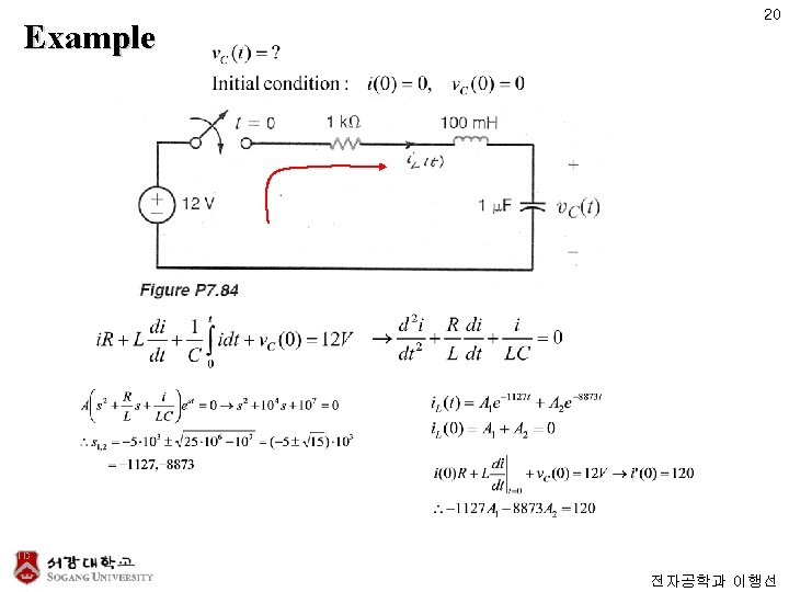
Second order transient circuit 16 전자공학과 이행선
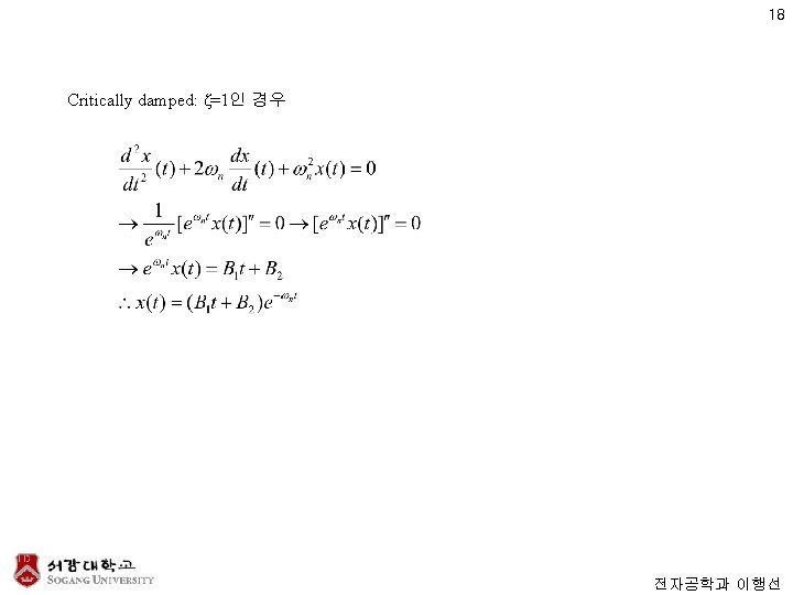
17 Solution Under-damped Over-damped Critically damped 전자공학과 이행선
19 Under-damped Over-damped Critically damped 전자공학과 이행선
21 8. AC steady-state analysis 전자공학과 이행선
Sinusoidal input signal 22 전자공학과 이행선
Sinusoids Dimensionless plot 23 As function of time 전자공학과 이행선
AC (Alternating Current) 24 • Easy to generate (교류 전압은 만들기 쉽다. ) • Easy to change voltage levels. (전압을 변화하기도 쉽다. ) • Less damage on human compared with DC (직류에 비해 덜 위험하다. ) 전자공학과 이행선
25 Solution of Differential Eq. To solve a differential equation, initial conditions must be specified. 전자공학과 이행선
26 Solution method #1 For a particular solution, choose a trial function that might produce VS(t) on entering the differential Eq. 전자공학과 이행선
Simpler method for sinusoidal source case 27 전자공학과 이행선
28 Phasor • With sinusoidal source function, it is simpler to use a trial solution ~ Re{I ejwt}. • The complex coefficient of the exponential function is called as a phasor. 전자공학과 이행선
Phasor - resistor 29 전자공학과 이행선
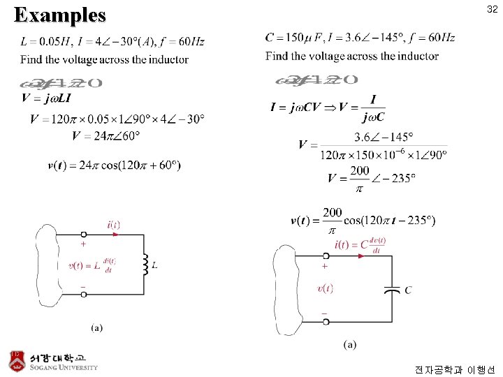
30 Phasor - inductor Relationship between sinusoids 전자공학과 이행선
31 Phasor - capacitor Relationship between sinusoids 전자공학과 이행선
Frequency response - resistor 33 If V/I ratio remains constant despite changes in source frequency, it is called a resistor. 전자공학과 이행선
Frequency response - capacitor 34 If the phase angle of current leads that of voltage, and the ratio of V/I decreases with higher frequency, it is called a capacitor. 전자공학과 이행선
Frequency response - inductor 35 If the phase angle of current lags behind that of voltage, and the ratio of V/I increases with higher frequency, it is called an inductor. 전자공학과 이행선
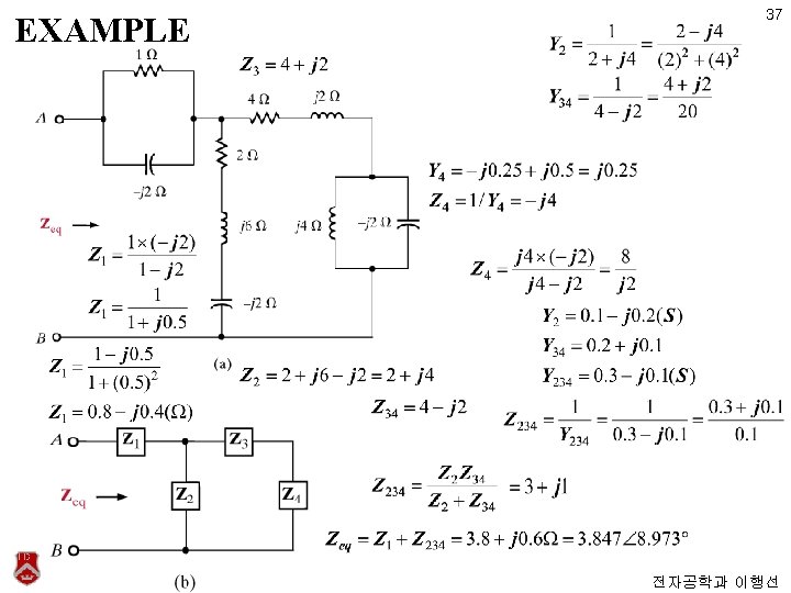
Impedance and Admittance 36 (INPUT) IMPEDANCE (DRIVING POINT IMPEDANCE) 전자공학과 이행선