THEO 13 Oct 28 2013 CERN Thorium Energy

- Slides: 59
THEO 13 (Oct. 28, 2013, CERN) Thorium Energy R&D in China Hongjie Xu, Xiangzhou Cai, Wei Guo TMSR Center of CAS Shanghai Institute of Applied Physics, Jialuo Road 2019, Jiading, Shanghai 201800, China
Outline Why TMSR Th-E @ TMSR Status and Progress
Outline Why TMSR Th-E @ TMSR Status and Progress
The Challenges to China And one possible solution
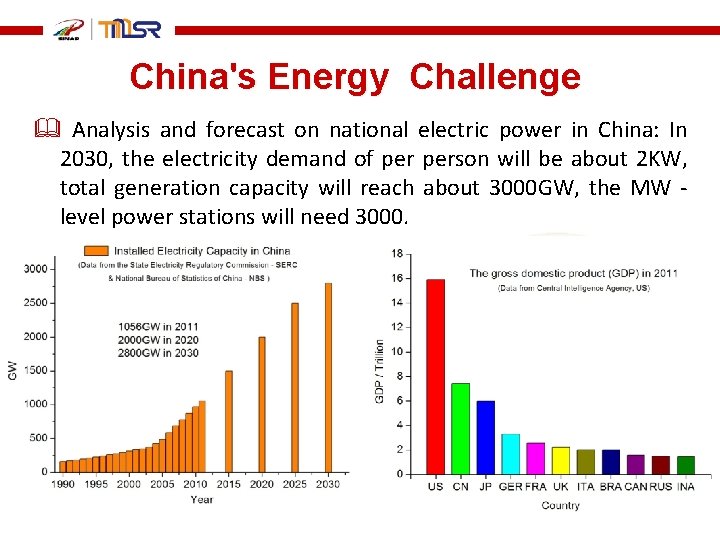
China's Energy Challenge Analysis and forecast on national electric power in China: In 2030, the electricity demand of person will be about 2 KW, total generation capacity will reach about 3000 GW, the MW - level power stations will need 3000.
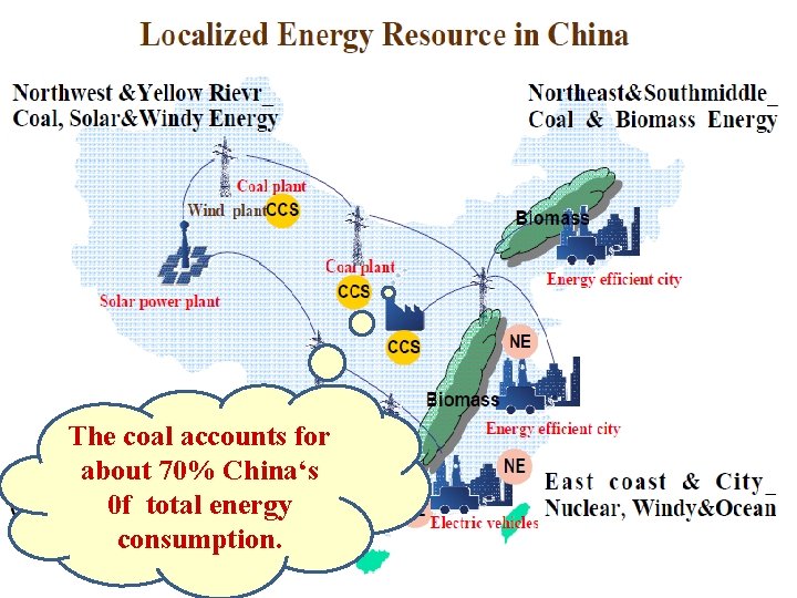
The coal accounts for about 70% China‘s 0 f total energy consumption.
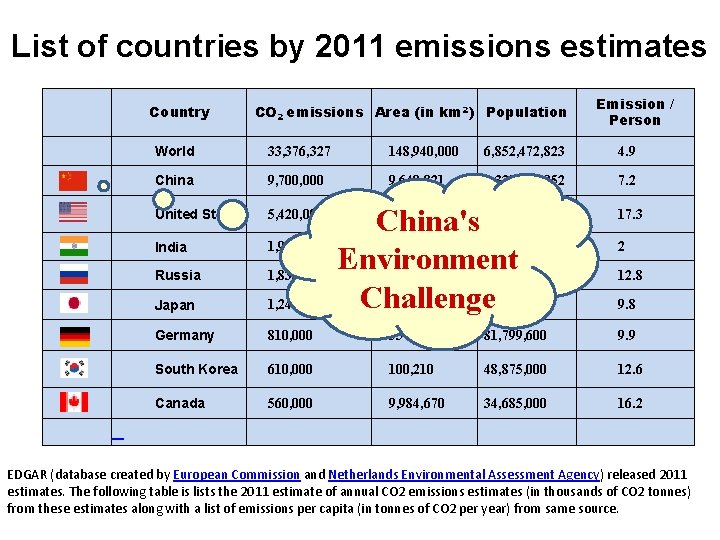
List of countries by 2011 emissions estimates Country Emission / Person CO 2 emissions Area (in km 2) Population World 33, 376, 327 148, 940, 000 6, 852, 472, 823 4. 9 China 9, 700, 000 9, 640, 821 1, 339, 724, 852 7. 2 United States 5, 420, 000 China's 312, 793, 000 3, 287, 263 1, 210, 193, 422 Environment 143, 300, 000 17, 075, 400 Challenge 377, 944 128, 056, 026 9, 826, 675 17. 3 India 1, 970, 000 Russia 1, 830, 000 Japan 1, 240, 000 Germany 810, 000 357, 021 81, 799, 600 9. 9 South Korea 610, 000 100, 210 48, 875, 000 12. 6 Canada 560, 000 9, 984, 670 34, 685, 000 16. 2 2 12. 8 9. 8 EDGAR (database created by European Commission and Netherlands Environmental Assessment Agency) released 2011 estimates. The following table is lists the 2011 estimate of annual CO 2 emissions estimates (in thousands of CO 2 tonnes) from these estimates along with a list of emissions per capita (in tonnes of CO 2 per year) from same source.
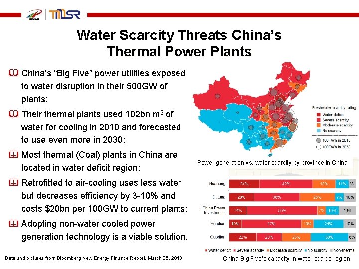
Water Scarcity Threats China’s Thermal Power Plants China’s “Big Five” power utilities exposed to water disruption in their 500 GW of plants; Their thermal plants used 102 bn m 3 of water for cooling in 2010 and forecasted to use even more in 2030; Most thermal (Coal) plants in China are located in water deficit region; Power generation vs. water scarcity by province in China Retrofitted to air-cooling uses less water but decreases efficiency by 3 -10% and costs $20 bn per 100 GW to current plants; Adopting non-water cooled power generation technology is a viable solution. Data and pictures from Bloomberg New Energy Finance Report, March 25, 2013 China Big Five’s capacity in water scarce region
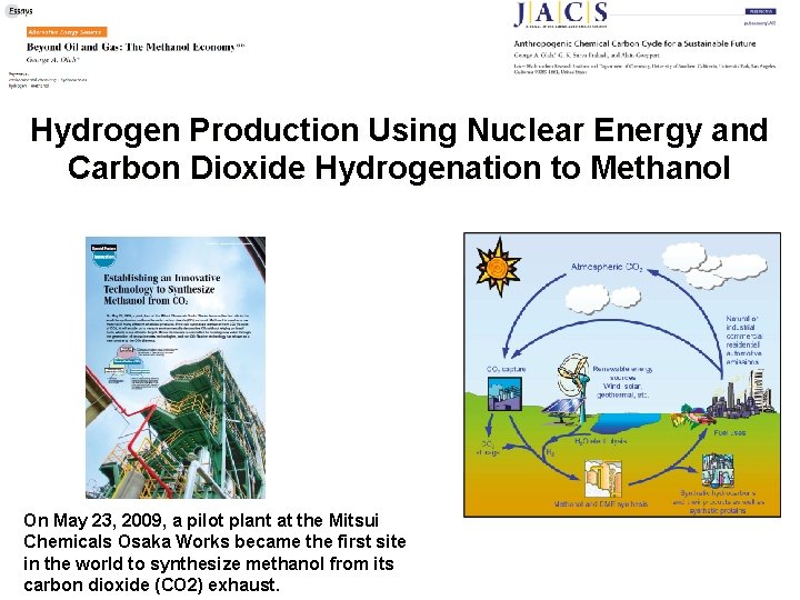
Hydrogen Production Using Nuclear Energy and Carbon Dioxide Hydrogenation to Methanol On May 23, 2009, a pilot plant at the Mitsui Chemicals Osaka Works became the first site in the world to synthesize methanol from its carbon dioxide (CO 2) exhaust.
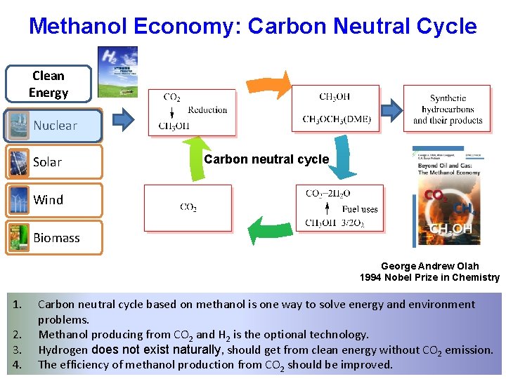
Methanol Economy: Carbon Neutral Cycle Clean Energy Nuclear Solar Wind Biomass Carbon neutral cycle George Andrew Olah 1994 Nobel Prize in Chemistry 1. 2. 3. 4. Carbon neutral cycle based on methanol is one way to solve energy and environment problems. Methanol producing from CO 2 and H 2 is the optional technology. Hydrogen does not exist naturally, should get from clean energy without CO 2 emission. The efficiency of methanol production from CO 2 should be improved.
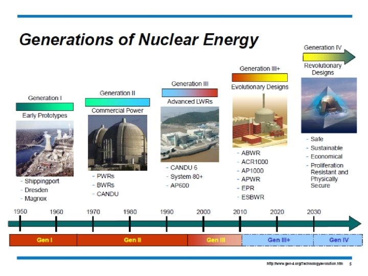
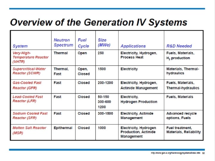
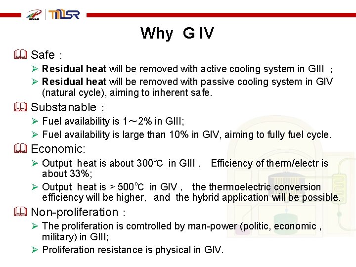
Why G IV Safe: Ø Residual heat will be removed with active cooling system in GIII ; Ø Residual heat will be removed with passive cooling system in GIV (natural cycle), aiming to inherent safe. Substanable: Ø Fuel availability is 1~ 2% in GIII; Ø Fuel availability is large than 10% in GIV, aiming to fully fuel cycle. Economic: Ø Output heat is about 300℃ in GIII , Efficiency of therm/electr is about 33%; Ø Output heat is > 500℃ in GIV , thermoelectric conversion efficiency will be higher,and the hybrid application will be possible. Non-proliferation: Ø The proliferation is comtrolled by man-power (politic, economic , military) in GIII; Ø Proliferation resistance is physical in GIV.
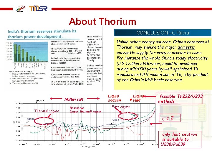
About Thorium CONCLUSION –C. Rubia Unlike other energy sources, China’s reserves of Thorium, may ensure the major domestic energetic supply for many centuries to come. For instance the whole China’s today electricity (3. 2 Trillion k. Wh/year) could be produced during ≈20’ 000 years by well optimized Th reactors and 8, 9 million ton of Th, a by-product of the China's REE basic reserves. Molten salt Thermal region Resonance (super thermal) region Liquid sodium Liquid lead Possible Th 232/U 233 methods Fast region =2 only fast neutron is suitable to U 238/Pu 239
TMSR
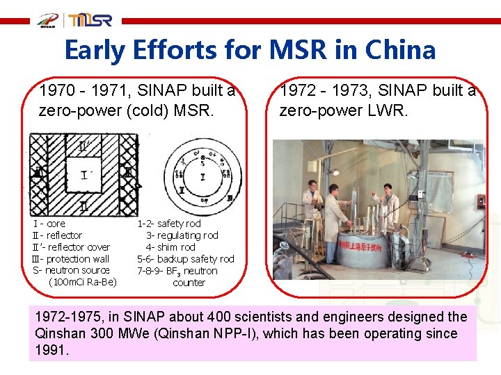
Early Efforts for MSR in China 1970 - 1971, SINAP built a zero-power (cold) MSR. Ⅰ- core Ⅱ- reflector Ⅱ’- reflector cover Ⅲ- protection wall S- neutron source (100 m. Ci Ra-Be) 1972 - 1973, SINAP built a zero-power LWR. 1 -2 - safety rod 3 - regulating rod 4 - shim rod 5 -6 - backup safety rod 7 -8 -9 - BF 3 neutron counter 1972 -1975, in SINAP about 400 scientists and engineers designed the Qinshan 300 MWe (Qinshan NPP-I), which has been operating since 1991.
Thorium Molten Salt Reactor Nuclear Energy System - TMSR The Aims of TMSR is to develop Th-Energy, Non-electric application of Nuclear Energy based on TMSR(LF) and TMSR(SF) during coming 20 -30 years. The program initiated by CAS from 2011 TMSR(LF) 液态燃料钍基熔盐堆 --- MSRs TMSR(RF) 固态燃料钍基熔盐堆 --- FHR s
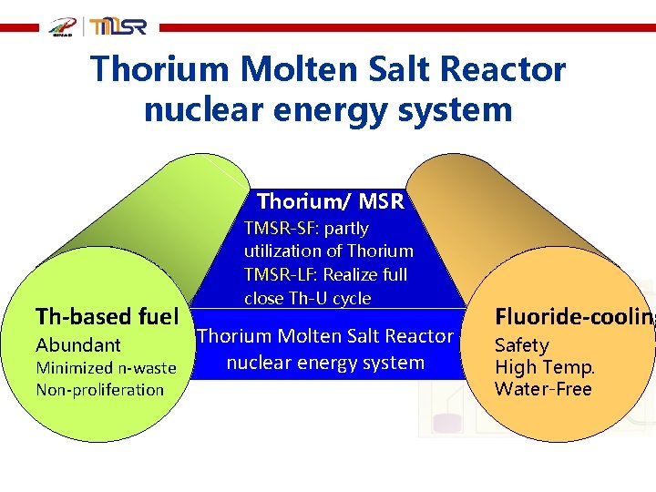
Thorium Molten Salt Reactor nuclear energy system 熔盐堆 Th-based fuel Abundant Minimized n-waste Non-proliferation Thorium/ MSR TMSR-SF: partly utilization of Thorium TMSR-LF: Realize full close Th-U cycle Thorium Molten Salt Reactor nuclear energy system Fluoride-cooling Safety High Temp. Water-Free
Outline Why TMSR Th-E @ TMSR Status and Progress
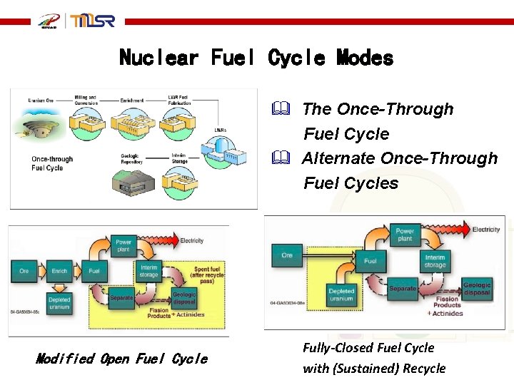
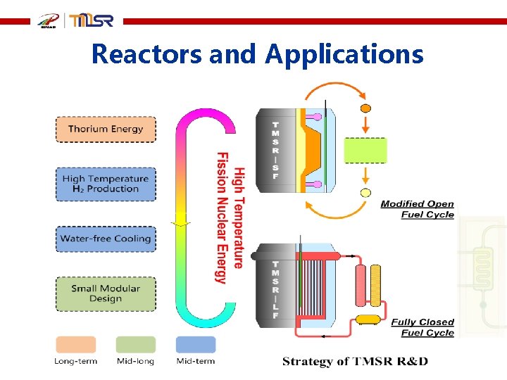
Nuclear Fuel Cycle Modes The Once-Through Fuel Cycle Alternate Once-Through Fuel Cycles Modified Open Fuel Cycle Fully-Closed Fuel Cycle with (Sustained) Recycle
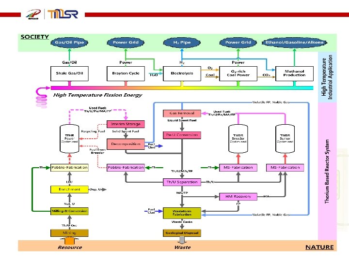
Reactors and Applications
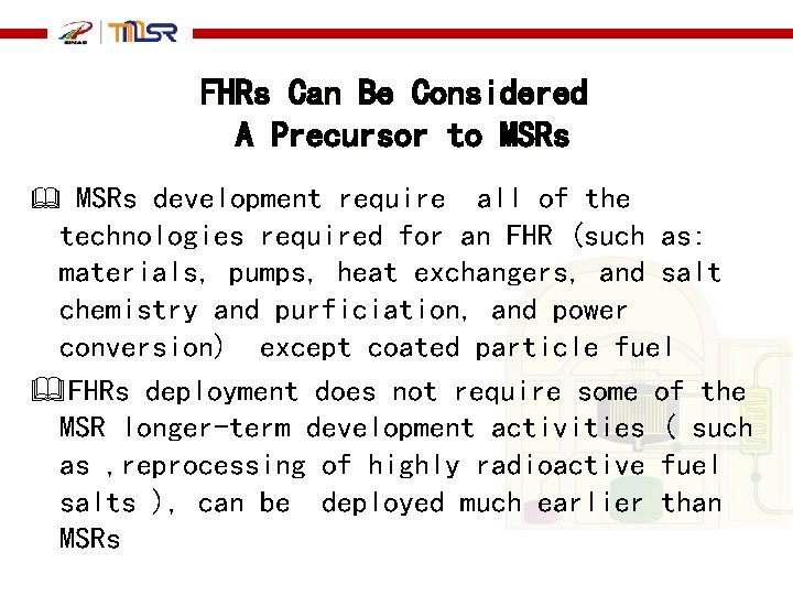
FHRs Can Be Considered A Precursor to MSRs development require all of the technologies required for an FHR (such as: materials, pumps, heat exchangers, and salt chemistry and purficiation, and power conversion) except coated particle fuel FHRs deployment does not require some of the MSR longer-term development activities ( such as , reprocessing of highly radioactive fuel salts ), can be deployed much earlier than MSRs
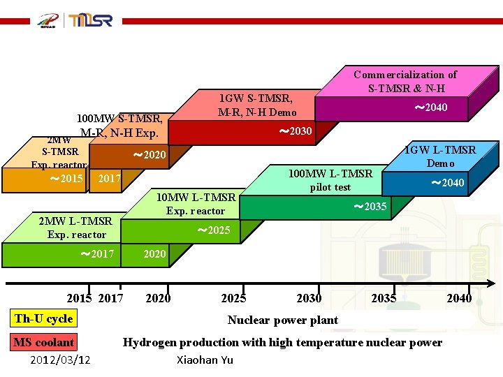
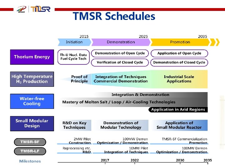
100 MW S-TMSR, 1 GW S-TMSR, M-R, N-H Demo ~ 2015 2 MW~ 2020 2017 10 MW L-TMSR Exp. reactor 2 MW 2015 2017 MS coolant 2012/03/12 100 MW L-TMSR pilot test 1 GW L-TMSR Demo ~ 2040 ~ 2035 ~ 2025 2020 ~ 2017 Th-U cycle ~ 2040 ~ 2030 M-R, N-H Exp. 2 MW S-TMSR Exp. reactor Commercialization of S-TMSR & N-H 2020 2025 2030 2035 Nuclear power plant Hydrogen production with high temperature nuclear power Xiaohan Yu 2040
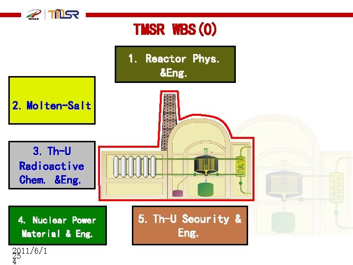
TMSR WBS(0) 1. Reactor Phys. &Eng. 2. Molten-Salt 3. Th-U Radioactive Chem. &Eng. 4. Nuclear Power Material & Eng. 2011/6/1 25 4 5. Th-U Security & Eng.
R&D abilities –I for TMSR deveopment TMSR reactor design and development. p Reactor core design: neutron physics, thermal hydraulics. . . p Engineering design and construction. p Key technologies and components. Developing safety codes and licensing
R&D abilities -II for TMSR deveopment Molten salt manufacturing techniques and molten salt loop techniques p Separation of 7 Li. p Purification of fluoride salt. p Design and construction of molten salt loops. p Development of key components for molten salt loop.
Materials for TMSRs p. Production, processing and testing of structure materials TMSR (Hastalloy-N, Graphite etc. ). p Carbon-based structure materials and components for TMSR p Effect and mechanism of material degrading under service condition.
Th/U fuel and Pyro-process techniques p Production of nuclear-grade Thorium fuel (both fluoride and oxide). p Triso fuel manufacturing p Pyro-process techniques for on-line (or in-site) offline) chemical separation of actinides and fission product for Th/U fuel cycle).
Techniques of Nuclear Hybrid Energy system 100 k. W CSP ( the salt is absorber and heat storage media) p Techniques for hydrogen producing p Methanol producing from CO 2 and H 2 p CSP techniques
Outline Why TMSR Th-E @ TMSR Status and Progress
TMSR Schedules
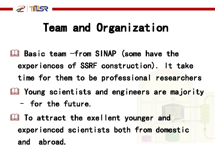
Team and Organization Basic team -from SINAP (some have the experiences of SSRF construction). It take time for them to be professional researchers Young scientists and engineers are majority – for the future. To attract the exellent younger and experienced scientists both from domestic and abroad.
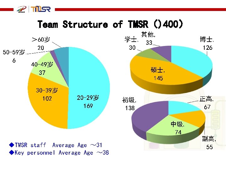
Team Structure of TMSR()400) u. TMSR staff Average Age ~ 31 u. Key personnel Average Age ~ 38
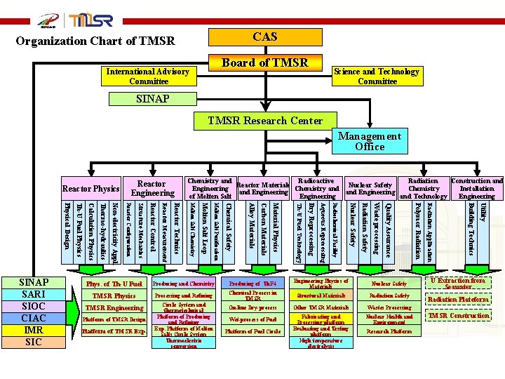
CAS Organization Chart of TMSR Board of TMSR International Advisory Committee Science and Technology Committee SINAP TMSR Research Center Management Office Reactor Physics Chemistry and Radioactive Radiation Construction and Reactor Materials Nuclear Safety Engineering Chemistry and Chemistry Installation and Engineering of Molten Salt Engineering and Technology Engineering Producing of Th. F 4 Engineering Physics of Materials Nuclear Safety TMSR Physics Processing and Refining Chemical Process in TMSR Structural Materials Radiation Safety TMSR Engineering Circle System and thermotechnical Platform of Producing and Refining Exp. Platform of Molten Salts Circle System Thermoelectric conversion On-line Dry-process Other TMSR Materials Wastes Processing Wet-process of Fuel Fabricating and Processing platform Evaluating and Testing platform High temperature electrolysis Nuclear Health and Environment Platform of TMSR Design Platform of TMSR Exp. Platform of Fuel Circle Research Platform Utility Producing and Chemistry Building Technics Phys. of Th-U Fuel Radiation Application Polymor Radiation Quality Assurance Waste processing Radiation Safety Nuclear Safety Radiochemical Facility Aqueous Reprocessing Dry Reprocessing Th-U Fuel Technology Material Physics Carbon Materials Alloy Materials Chemical Safety Molten Salt Purification Molten Salt Loop Molten Salt Chemistry Reactor Technics Reactor Measurement Reactor Control Structure Mechanics Reactor Configuration Non-electricity Appl. Thermo-hydraulics Calculation Physics Th-U Fuel Physics Physical Design SINAP SARI SIOC CIAC IMR SIC Reactor Engineering U Extraction from Seawater Radiation Plateform TMSR Construction
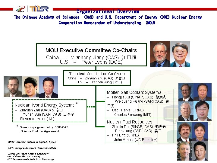
Organizational Overview The Chinese Academy of Sciences (CAS) and U. S. Department of Energy (DOE) Nuclear Energy Cooperation Memorandum of Understanding (MOU) MOU Executive Committee Co-Chairs China – Mianheng Jiang (CAS) 江� 恒 U. S. – Peter Lyons (DOE) Technical Coordination Co-Chairs China – Zhiyuan Zhu (CAS) 朱志� U. S. – Stephen Kung (DOE) Molten Salt Coolant Systems Nuclear Hybrid Energy Systems * – Zhiyuan Zhu (CAS) 朱志� Yuhan Sun (SARI, CAS) � 予罕 – Steven Aumeier (INL) * Work scope governed by DOE-CAS Science Protocol Agreement SINAP : Shanghai Institute of Applied Physics SARI: Shanghai Advanced Research Institute ORNL: Oak Ridge National Laboratory INL: Idaho National Laboratory MIT: Massachusetts Institute of Technology – Hongjie Xu (SINAP, CAS) 徐洪杰 Weiguang Huang (SARI, CAS) 黄 �光 – Cecil Parks (ORNL) Charles Forsberg (MIT) Nuclear Fuel Resources – Zhimin Dai (SINAP, CAS) 戴志敏 Biao Jiang (SARI, CAS) 姜� – Phil Britt (ORNL) John Arnold (UC-Berkeley)
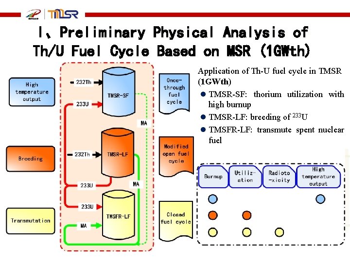
I、Preliminary Physical Analysis of Th/U Fuel Cycle Based on MSR (1 GWth) Application of Th-U fuel cycle in TMSR (1 GWth) l TMSR-SF: thorium utilization with high burnup l TMSR-LF: breeding of 233 U l TMSFR-LF: transmute spent nuclear fuel
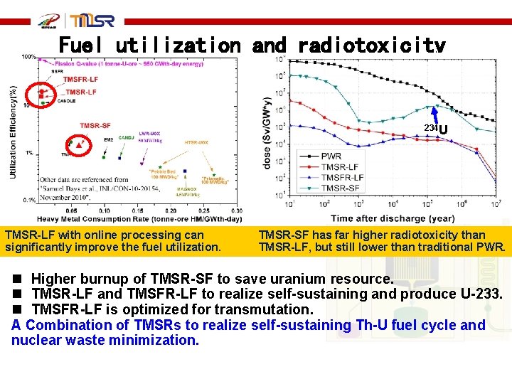
Fuel utilization and radiotoxicity 234 U TMSR-LF with online processing can significantly improve the fuel utilization. TMSR-SF has far higher radiotoxicity than TMSR-LF, but still lower than traditional PWR. n Higher burnup of TMSR-SF to save uranium resource. n TMSR-LF and TMSFR-LF to realize self-sustaining and produce U-233. n TMSFR-LF is optimized for transmutation. A Combination of TMSRs to realize self-sustaining Th-U fuel cycle and nuclear waste minimization.
II、Goals and physical design for TMSR-SF 1 Form abilities for design: physics design, thermal-hydralics design, safety system design and engineer design Form abilities for integration, operation and maintenance. Verify characteristics of FHR: physics behavior, safety behavior and thermal-hydralics behavior Research behavior of material and fuel From partition flow pebble bed design to No-partition ordered pebble bed design
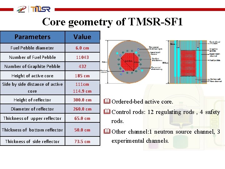
Core geometry of TMSR-SF 1 Parameters Value Fuel Pebble diameter 6. 0 cm Number of Fuel Pebble 11043 Number of Graphite Pebble 432 Height of active core 185 cm Side by side distance of active core 111 cm 114. 9 cm Height of reflector 300. 0 cm Diameter of reflector 260. 0 cm Thickness of upper reflector 65. 0 cm Thickness of bottom reflector 50. 0 cm Thickness of side reflector 73. 5 cm Ordered-bed active core. Control rods: 12 regulating rods , 4 safety rods. Other channel: 1 neutron source channel, 3 experimental channels.
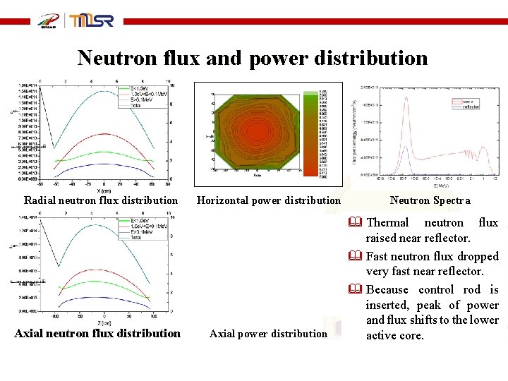
Neutron flux and power distribution Radial neutron flux distribution Axial neutron flux distribution Horizontal power distribution Axial power distribution Neutron Spectra Thermal neutron flux raised near reflector. Fast neutron flux dropped very fast near reflector. Because control rod is inserted, peak of power and flux shifts to the lower active core.
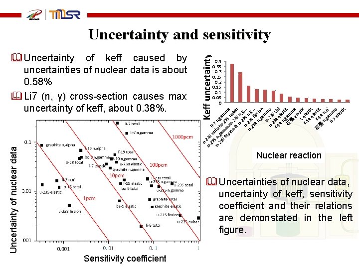
0. 4 0. 35 0. 3 0. 25 0. 2 0. 15 0. 1 0. 05 0 uu- 235 23 n liu- 5 n, uba 7 n, 23 ga ru ga 5 m -2 m fis m 35 m sio au n a n -23 ub & 5 ar u- n 2 , g u- 35 . . . 2 u- 3 n, g 23 5 f. . . 8 iss n, io ga n u- mm u- 23 a 2 5 f-1 38 ch 9 ela i n, st 石 gam ic 墨 m e a la c e stic f-1 la 9 stic el 石 f- asti 墨 19 c n n, , g n a ' li- mm 7 a el as tic Uncertainty of nuclear data Uncertainty of keff caused by uncertainties of nuclear data is about 0. 58% Li 7 (n, γ) cross-section causes max uncertainty of keff, about 0. 38%. Keff uncertainty % Uncertainty and sensitivity 核反� Nuclear reaction Uncertainties of nuclear data, uncertainty of keff, sensitivity coefficient and their relations are demonstated in the left figure. Sensitivity coefficient
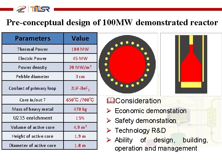
Pre-conceptual design of 100 MW demonstrated reactor Parameters Value Thermal Power 100 MW Electric Power 45 MW Power density 20 MW/m 3 Pebble diameter 3 cm Coolant of primary loop 2 Li. F-Be. F 2 Core in/out T 650℃ /700℃ Mass of heavy metal 470 kg U 235 enrichment 15% Volume of active core 4. 9 m 3 Height of active core 1. 9 m Diameter of active core 1. 8 m Consideration Ø Ø Economic demonstation Safety demonstation Technology R&D Ability of design, building, operation and management
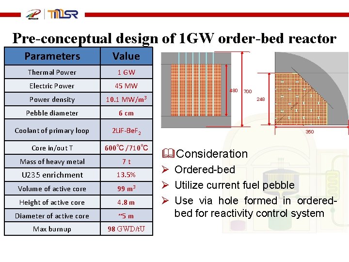
Pre-conceptual design of 1 GW order-bed reactor Parameters Value Thermal Power 1 GW Electric Power 45 MW Power density 10. 1 MW/m 3 Pebble diameter 6 cm Coolant of primary loop 2 Li. F-Be. F 2 Core in/out T 600℃ /710℃ Mass of heavy metal 7 t U 235 enrichment 13. 5% Volume of active core 99 m 3 Height of active core 4. 8 m Diameter of active core ~5 m Max burnup 98 GWD/t. U 480 700 248 350 Consideration Ø Ordered-bed Ø Utilize current fuel pebble Ø Use via hole formed in orderedbed for reactivity control system
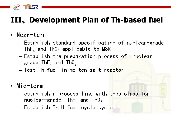
III、Development Plan of Th-based fuel • Near-term – Establish standard specification of nuclear-grade Th. F 4 and Th. O 2 applicable to MSR – Establish the preparation process of nucleargrade Th. F 4 and Th. O 2 – Test Th fuel in molten salt reactor • Mid-term – establish a process line with tons class for nuclear-grade Th. F 4 and Th. O 2 – Establish Th-U fuel cycle system
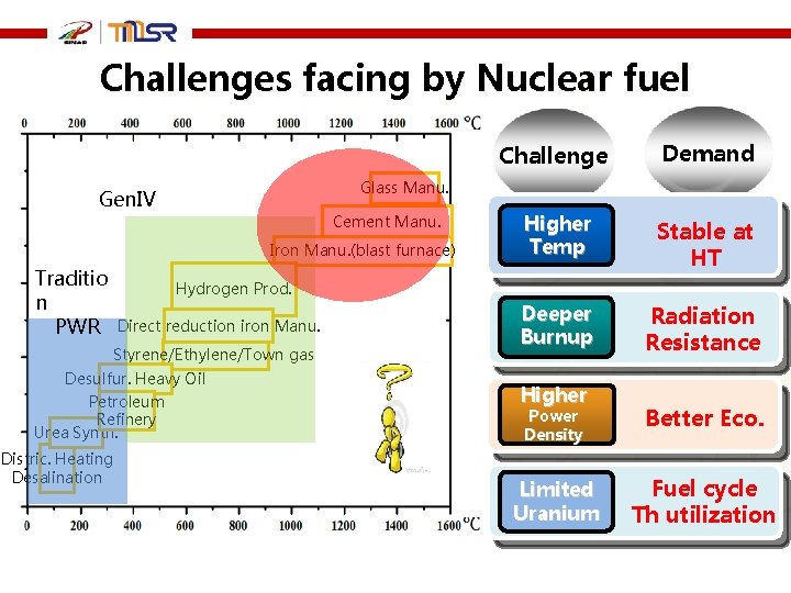
Challenges facing by Nuclear fuel Demand Higher Temp Stable at HT Deeper Burnup Radiation Resistance Glass Manu. Gen. IV Cement Manu. Iron Manu. (blast furnace) Traditio n PWR Challenge Hydrogen Prod. Direct reduction iron Manu. Styrene/Ethylene/Town gas Desulfur. Heavy Oil Petroleum Refinery Urea Synth. Higher Distric. Heating Desalination Power Density Better Eco. Limited Uranium Fuel cycle Th utilization
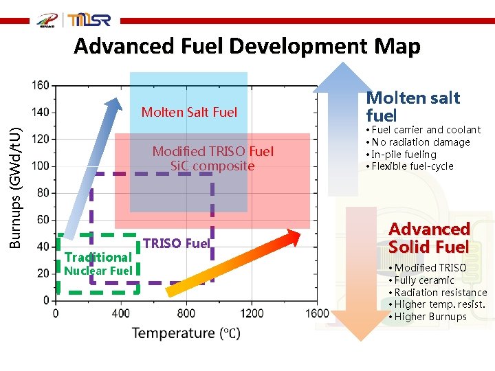
Advanced Fuel Development Map Burnups (GWd/t. U) Molten Salt Fuel Modified TRISO Fuel Si. C composite Traditional Nuclear Fuel TRISO Fuel Molten salt fuel • Fuel carrier and coolant • No radiation damage • In-pile fueling • Flexible fuel-cycle Advanced Solid Fuel • Modified TRISO • Fully ceramic • Radiation resistance • Higher temp. resist. • Higher Burnups
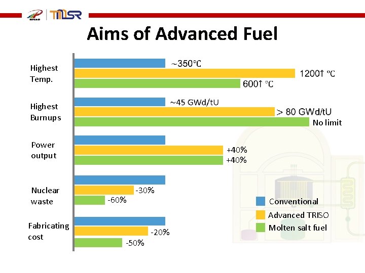
Aims of Advanced Fuel Highest Temp. Highest Burnups Power output Nuclear waste Fabricating cost No limit +40% -60% -30% -50% Conventional -20% Advanced TRISO Molten salt fuel
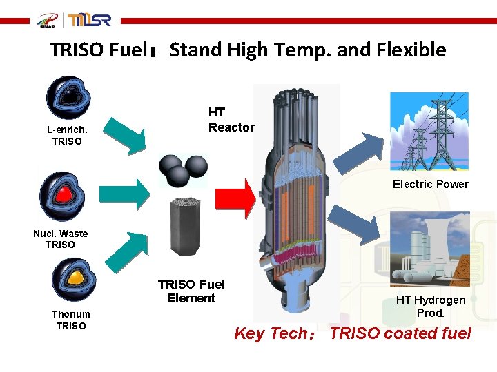
TRISO Fuel:Stand High Temp. and Flexible L-enrich. TRISO HT Reactor Electric Power Nucl. Waste TRISO Fuel Element Thorium TRISO HT Hydrogen Prod. Key Tech: TRISO coated fuel
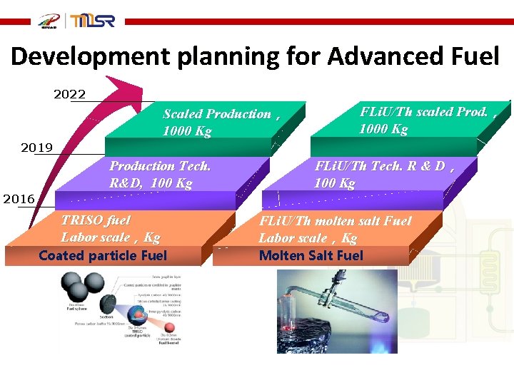
Development planning for Advanced Fuel 2022 Scaled Production, 1000 Kg FLi. U/Th scaled Prod. , 1000 Kg 2019 Production Tech. R&D, 100 Kg FLi. U/Th Tech. R & D, 100 Kg 2016 TRISO fuel Labor scale,Kg Coated particle Fuel FLi. U/Th molten salt Fuel Labor scale,Kg Molten Salt Fuel
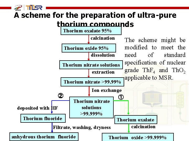
A scheme for the preparation of ultra-pure thorium compounds Thorium oxalate 95% calcination The scheme might be modified to meet the Thorium oxide 95% dissolution need of standard Thorium nitrate solutions specification of nuclear grade Th. F 4 and Th. O 2 extraction applicable to MSR. Thorium nitrate >99. 99% Ion exchange ② ① Thorium nitrate solutions deposited with HF >99. 999% Thorium fluoride Thorium oxalate calcination Filtrate, washing, dryness anhydrous thorium fluoride anhydrous Thorium oxide >99. 999%
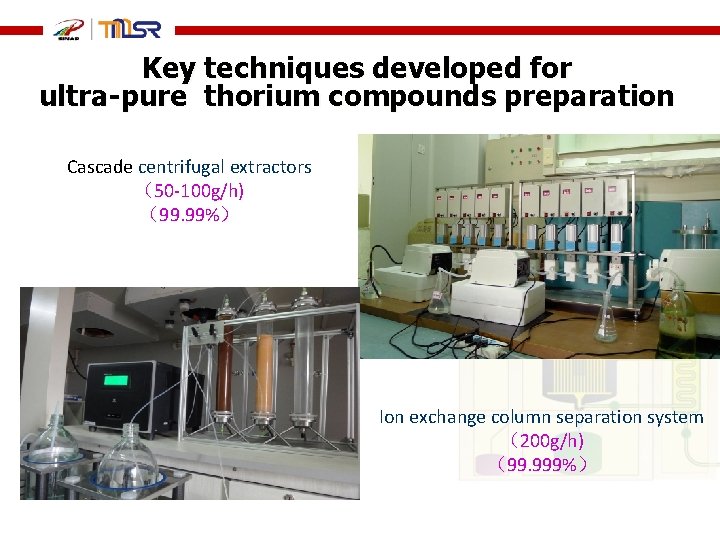
Key techniques developed for ultra-pure thorium compounds preparation Cascade centrifugal extractors (50 -100 g/h) (99. 99%) Ion exchange column separation system (200 g/h) (99. 999%)
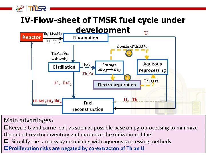
IV-Flow-sheet of TMSR fuel cycle under development U Th, U, Pa, FPs Reactor Li. F-Be. F 2 Fluorination Fluorides of Th, U, FPs 1 Th, Pa, FPs, Li. F-Be. F 2 Distillation FPs Th, Pa Li. F、Be. F 2 Li. F-Be. F 2 -UF 4 -Th. F 4 Main advantages: Aqueous reprocessing Storage 233 Pa 233 U 2 Electro-separation Fuel reconstruction Th, U, FPs U,Th p. Recycle U and carrier salt as soon as possible base on pyroprocessing to minimize the out-of-reactor inventory and maximize the utilization of fuel p Simplify the process by combining with aqueous processing methods p. Proliferation risks are negated by co-extracton of Th an U
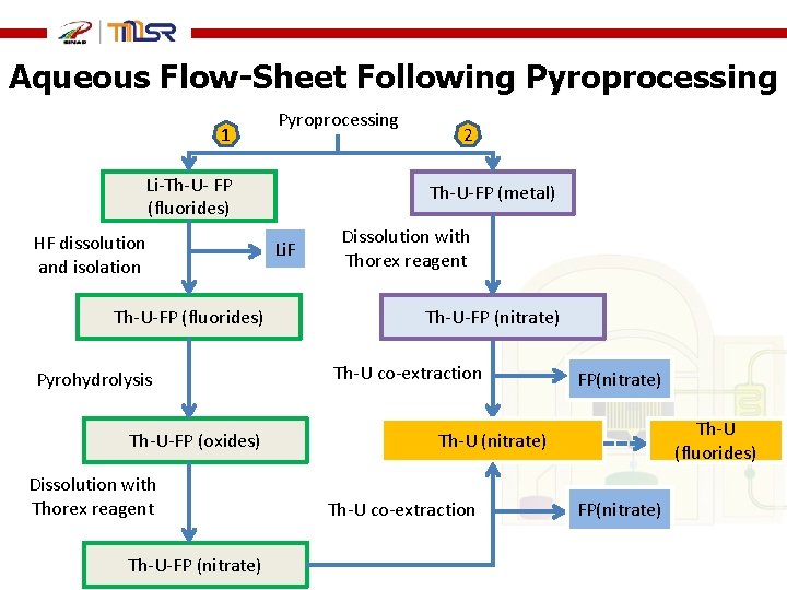
Aqueous Flow-Sheet Following Pyroprocessing 1 Pyroprocessing Li-Th-U- FP (fluorides) HF dissolution and isolation Th-U-FP (fluorides) Pyrohydrolysis Th-U-FP (oxides) Dissolution with Thorex reagent Th-U-FP (nitrate) 2 Th-U-FP (metal) Li. F Dissolution with Thorex reagent Th-U-FP (nitrate) Th-U co-extraction FP(nitrate) Th-U (fluorides) Th-U (nitrate) Th-U co-extraction FP(nitrate)
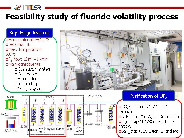
Feasibility study of fluoride volatility process Key design features p. Main material: HC-276 p Volume: 1 L p. Max. Temperature: 600℃ p. F 2 flow: 10 ml~ 1 l/min p. Main constituents: p. Gas supply system p. Gas preheater p. Fluorinator pabsorb traps p. Off-gas system Purification of UF 6 p. UO 2 F 2 55 trap (150 ℃) for Pu removal p. Na. F trap (350℃) for Ru and Nb p. Mg. F 2 trap (125℃) for Nb, Mo and Sb p. Ba. F 2 trap (125℃)for Ru and Mo
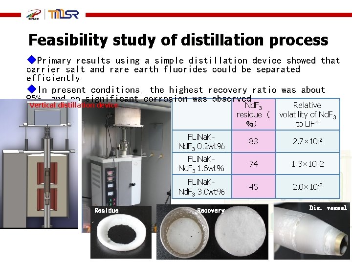
Feasibility study of distillation process u. Primary results using a simple distillation device showed that carrier salt and rare earth fluorides could be separated efficiently u. In present conditions, the highest recovery ratio was about 95%, and no significant corrosion was observed Nd. F 3 residue( %) Relative volatility of Nd. F 3 to Li. F* FLi. Na. KNd. F 3 0. 2 wt% 83 2. 7× 10 -2 FLi. Na. KNd. F 3 1. 6 wt% 74 1. 3× 10 -2 FLi. Na. KNd. F 3 3. 0 wt% 45 2. 0× 10 -2 Vertical distillation device Residue Recovery Dis. vessel
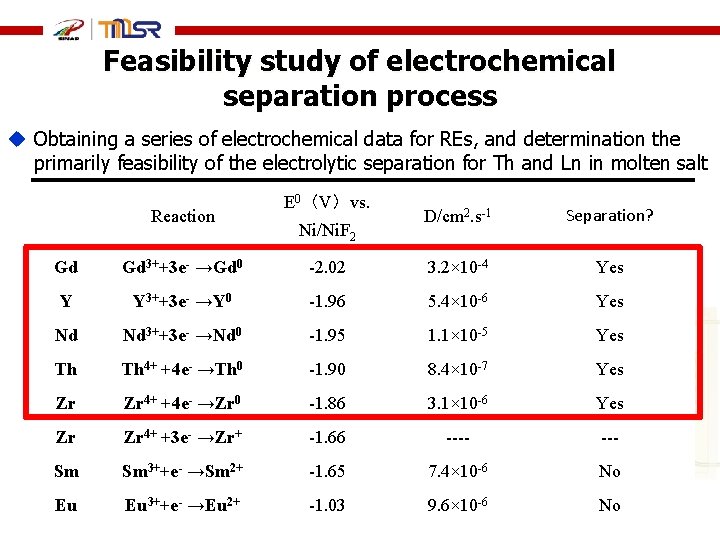
Feasibility study of electrochemical separation process u Obtaining a series of electrochemical data for REs, and determination the primarily feasibility of the electrolytic separation for Th and Ln in molten salt Reaction E 0(V)vs. Ni/Ni. F 2 D/cm 2. s-1 Separation? Gd Gd 3++3 e- →Gd 0 -2. 02 3. 2× 10 -4 Yes Y Y 3++3 e- →Y 0 -1. 96 5. 4× 10 -6 Yes Nd Nd 3++3 e- →Nd 0 -1. 95 1. 1× 10 -5 Yes Th Th 4+ +4 e- →Th 0 -1. 90 8. 4× 10 -7 Yes Zr Zr 4+ +4 e- →Zr 0 -1. 86 3. 1× 10 -6 Yes Zr Zr 4+ +3 e- →Zr+ -1. 66 ---- Sm Sm 3++e- →Sm 2+ -1. 65 7. 4× 10 -6 No Eu Eu 3++e- →Eu 2+ -1. 03 9. 6× 10 -6 No
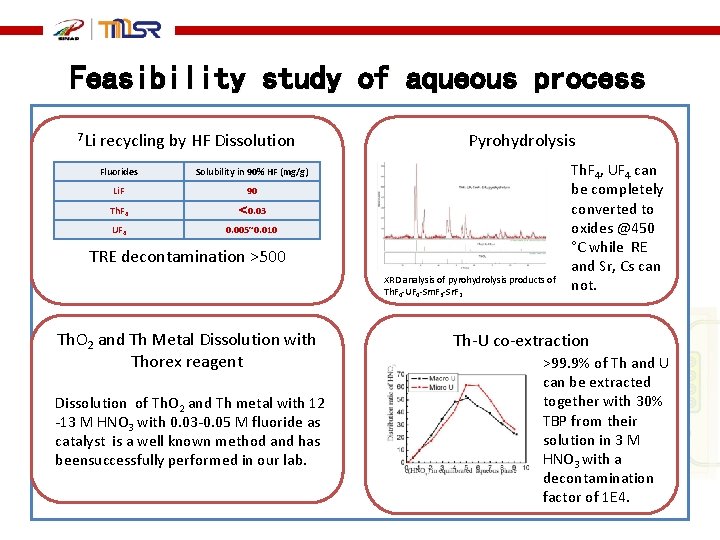
Feasibility study of aqueous process 7 Li recycling by HF Dissolution Fluorides Solubility in 90% HF (mg/g) Li. F 90 Th. F 4 < 0. 03 UF 4 0. 005~0. 010 Pyrohydrolysis TRE decontamination >500 XRD analysis of pyrohydrolysis products of Th. F 4 -UF 4 -Sm. F 3 -Sr. F 2 Th. O 2 and Th Metal Dissolution with Thorex reagent Dissolution of Th. O 2 and Th metal with 12 -13 M HNO 3 with 0. 03 -0. 05 M fluoride as catalyst is a well known method and has beensuccessfully performed in our lab. Th. F 4, UF 4 can be completely converted to oxides @450 ˚C while RE and Sr, Cs can not. Th-U co-extraction >99. 9% of Th and U can be extracted together with 30% TBP from their solution in 3 M HNO 3 with a decontamination factor of 1 E 4.
Thank you for your Attention!