SOLAR RADIATION ContextImportance of solar radiation measurements Energy


- Slides: 95

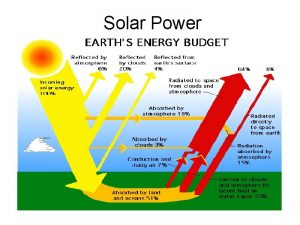
SOLAR RADIATION • Context/Importance of solar radiation measurements – – Energy available to Earth Atmospheric circulation Here: microscale energy balance: turbulence generation Almost 50% of short-wave radiation absorbed by surface and changed into th-IR • Types of radiation (irradiation W/m 2) – Direct solar radiation – Diffuse solar radiation (scattering and recflections) – Global solar radiation hemispherical (2 steradians) – Spectral range from 300 to 3000 nm

SENSOR TYPES: AN OVERVIEW OF TECHNOLOGIES • Direct solar radiation: Pyrheliometers – Tracking of solar position (azimuth and zenith angles) • Net radiation level: Radiometers – Sum of direct and diffuse solar radiation minus reflected • PPFD: Quantum sensors – Photosynthetic light spectrum or PPFD • Total (global) radiation: Pyranometers – Thermopile arrays • Electrical output prop. to absorbed radiation • Thermocouples in series or in parallel – Photovoltaic detectors • Si – photodiodes (barrier-layer cell) • Potential at junction between two materials • Rapid response time

OUR CHOICE: THE DAVIS SOLAR RADIATION SENSOR 6450 • General information – – Si photodiode with wide spectral response (sealed) Convection cooling of body, run-off path for water Cutoff ring for cosine response, level indicater, alignment fins In-build amplifier • Manufacturer’s specifications – Power requirements: 3 VDC ( 10%); 1 m. A; 3 m. W – Analog output [0, +3 VDC]; 1. 67 m. V per W/m 2 – Operating environmental conditions: • Temperature: -40° to +65°C • Temperature corrections: coeff = 0. 12% per °C; ref temp = 25°C – Sensor specifications • • • Spectral response: 400 (300) to 1100 nm Output Range: 0 to 1800 W/m 2 Cosine Response 3% (0°-70° i. angle); 10% (70°-80°i. a. ) Accuracy: 5% of full scale (ref: Eppley PSP at 1000 W/m 2) Drift: up to 2% per year

OUR CHOICE: THE DAVIS SOLAR RADIATION SENSOR 6450 • Sensor components and dimensions – – Diffuser with ‘excellent’ cosine response Cable (industrial version: 5 m) Dimensions: 51 mm x 70 mm x 57 mm Weight: 226 g • Mounting – – Top of stand Needs flat surface with holes for fixing 3 screws and springs for levelling Fins for optical alignment

CALIBRATION REQUIREMENTS IMPROVED ACCURACY LOW-COST SENSORS • Studies by King et al. at Sandia National Laboratories – Achieve better accuracy ( 3%) using photodiodes instead of expensive thermopile devices ( 2%) • Main factors influencing accuracy – Solar spectral influence – Solar angle-of-incidence • Sensor’s response to direct irradiance influenced by cosine of solar AOI & optical characteristics of front surface • Significant measurement errors at high AOI – Operating temperature • Calibration methodology – Determine AMa and AOI functions (empirical curves) – Determine calibration constant Cn (in m. V) for standardized AMa solar spectra, at a reference temperature To – Apply corrections for an improved estimate of the total (broadband) irradiance Et:

CALIBRATION REQUIREMENTS IMPROVED ACCURACY LOW-COST SENSORS • Solar spectral influence – Changes of solar spectral distribution over the day – Compute spectral mismatch parameter M (ASTM) – Option to relate M to the absolute optical airmass AMa and obtain a continuous spectral mismatch parameter • Solar angle-of-incidence – Influence depends on pyranometer’s optical characteristics (diffuser) – AOI function • Operating temperature • Other factors: – Mechanical and optical asymmetries, linearity of response, path across pyranometer, response time, stability

CALIBRATION REQUIREMENTS CLASSIFICATION & INDICATIONS • WMO classification of Davis 6450 pyranometer – Second class pyranometer • WMO calibration methods (using sun or lab source) – Comparison with standard pyrheliometer – Comparison with standard pyranometer (natural conditions) – Comparison on laboratory optical bench – Comparison in laboratory integrating chambers – Calibrate in the normal position of use • Comparison with reference pyranometer – – – Simultaneous operation of both instruments Long period for representative results in typical conditions Calibration factor: k = R kr (R-response ratio test/reference) Take temperature into account Davis sensors individually calibrated against secondary standard – standard calibrated against Eppley Precision Spectral Pyranometer in natural daylight

SITE SELECTION CONSIDERATIONS • Site selection – – – – Site should be free from any obstruction above plane of sensing element Shadow possibilities at any time of year have to be taken into account Should be away from light-coloured walls or reflective objects Should not be exposed to artificial radiation sources Keep at certain distance from buildings or obstructions Here: these considerations will probably not be taken into account Avoid vibrations due to high winds, use rigid platform • Installation – Careful optical levelling of instrument, check plotting irradiance throughout a day – Maximum cable length and weatherproofed junctions • Operation – Sampling rate – Integration of data

MAINTAINANCE REQUIREMENTS • Inspection frequencies (ASTM standards) – Daily for cleaning – Semi-annual for inclination angle verification – Annual for recalibration and general deterioration inspection • Care and maintainance – Wipe dry and clean diffuser using cloth and ethyl alcohol – Gently remove solid deposits: frozen snow, frost or rime • Recalibration – Observed annual drift of 2%, for higher accuracy, calibrate once a year – Basic calibration procedures should be employed if preserved standards available – Quality control with long-term plots of solar noon irradiance value during clear sky conditions

Si Photodiode Visible to UV • What is a photodiode? -> A component semiconductor able to detect a radiation, which collects the visible signal and transforms it into electric signal. Family of the active photoreceivers, it requires to be polarized in reverse by an external food. -> 3 distinct areas are located: • • • charging space (ZCE) Neutral region of type N Neutral region of type P

Si Photodiode Visible to UV • Dimensional outlines -> Side View: Width: 5, 5 mm Width window: 3, 1 mm Height: 16, 5 mm -> Top View: Distance connects: 2, 55 mm

Si Photodiode Visible to UV • General Characteristics : - package= 18 mm - Active area size= 1, 2 mm 2 - Reverse voltage(VRMax)= 30 Volts - Operating temperature(Topr)= -40 to +100 - Storage temp. (Tstg)= -55 to +125 celsius -> Analogical dispositif with borosilicate glass

Si Photodiode Visible to UV • Electrical and optical Characteristics : -Spectral response range from 320 to 1100 nm - Peak (sensitivity wave length) lambda= 960 nm « spectral response » - Photo. Sensitivity (S)= 0, 6 (A/W) « photosensitivity »

Si Photodiode Visible to UV Warning: Photodiodes (Ge) have a more significant photosensitivity but their dark current is notable ID = 10 u. A. It is thus preferable to use photodiodes (Si) (ID near 10 p. A) for the detection of weak illuminations. -Dark current ID= 2 p. A - Temp. coefficient of ID= 1, 12 times / degree

Si Photodiode Visible to UV • Electrical and optical Characteristics : - Rise time : 0, 4 micro sec. «rise time/ load resistance» - Terminal capacitance(Ct)= 140 p. F - Shunt resistance (Rsh)= 5 to 100 GOhm « shunt resistance » This device goes to necessite the use of an amplifier of impedance. About alternative technologies we have: laser, and every works with wavelength.

Si Photodiode Visible to UV • Precision and accuracy: - Near the microseconde - High reliability - High linearity(->relationship between the collected ray and the electrical current product is strictly linear) • Maintenance requirements - The cellule must be always clean to intercept radiations clearly with no wrong ways and any shade about objects have to affect our measurements.

Infra. Red Thermometer (IRT) • Sensor to get Skin Temperature Canopy Surfaces(Ground, Wall, Roof, …) • Anything above «Absolute Zero» radiates in the IR + : Everything can be measured - : Risk of Perturbations

Compounds Infomations • IR Thermopile Detector Target Wave Length : 5 m -14 m Atmospheric Window (H 2 O, CO 2, CH 4, …) • Temperature Sensor Environment

IRT Specifications • • Operating Power Requirements : Voltage 3 V 4. 5 V Current 4 A 6 A Output Format : - Voltage Output Conversion (Analog) (expected ranges : 0 - 10 V, 4 - 20 m. A) - CPU (chip) converts Analog signal into Digital

IRT Specifications • Range of environmental Conditions : - Temperature : Measurement Range Operating Range -33° 220°C -10° 50°C - Emissivity of Materials (Function of T°) : High Emissivity : Plastic, Glass, Ceramics, Water, Soil, … Low Emissivity : Gold, Aluminium, shiny Objects - Field of View : Distance of Sensor Spot Size on Surface

IRT Specifications • Accuracy : Thermopile Depends on neighbourhood Temperature e. M +/- 15° T° +/- 0. 5° Error on Measurment when ambiant T° = 25° Relative Measurment Error min : ambiant T° = target T°

Alternative technologies • Thermocouple : 2 dissimilar Metals are joined When Junction is heated (or cooled), a Voltage is produced • Resistance Temperature Detector (RTD) : Composed of a Material which has well known «Temp – Res» Relationship. Most accurate Sensor, Stability & Sepeatability Both are contact Sensors, that means they have to be close to the Surface.

Calibrations & Maintenance • Blackbody Cavity (commercial) : Standard Method for Calibration (emissivity : ε =1) • need to get ε-Target from Tables • On Field : Has to be done for specific Surface Properties use Hand-held with auto ε-compensation system • Test Calibration Frequency Requirement : Drift ? Emissivity changes ?

Sites Selection As many representative Samples as possible… • Different Exposition Surfaces : Ground, Wall and Roof Sunny vs. Shaded Sites • Different Surface Types (with high ε) : Concrete, Brick, Asphalt, Glass, Gravels, …

Notices… • Still no Information about how to fix IRT on Stands • Many Certifications about the Products (e. g. ISO 9001) • Not a lot of Specific Informations about the sensor TN 0 am Difficulty to be informed through the website !! • References : www. zytemp. com (choosen Instrument) www. apogeeinstruments. com www. hukseflux. com www. omega. com


Measurement of Surface Wind • Wind direction • Wind speed meteorological forecast Naval war strategy • Modern wind sensors – Anemometers based on cooling effect of wind – Anemometers based on air movement – Anemometers based on wind force

Wind measurement • Wind speed Definition: - Wind velocity - Average over 10 min • Wind direction Definition: - Direction from which wind is blowing - Geographical north - Calm Units: m/s or knots Units: degrees

Wind Sensors: Davis anemometer • Cup rotor => Measures wind speed • Direction vane => Measures wind direction

Wind speed sensor: Two sub-assemblies Rotor: • Proportional to wind speed • Problem with starting threshold speed • Response to change in wind speed = distance constant Signal generator: • Reed switch in anemometer head unit • Magnet in the wind cup assembly => Circuit closure

Wind direction vane: Two sub-assemblies Vane: • Well-balanced • One-single equilibrium position Signal generator: • Shaft angle transducer • 360º Potentiometer • Resistance: 0 -20 K Ohms • Input Voltage: 3 V • Output voltage • Analog signal

Range and Accuracy: Range: • Wind speed • Wind direction Accuracy: • Wind speed • Wind direction Resolution: • Wind speed • Wind direction 0. 9 -78 m/s 0 -360° or 16 compass points 5% 7° 1 mph 1°

Environmental Conditions • Freezing Conditions => Use of drip rings • Hurricane and light breeze => Wind tunnel testing Maintenance • No maintenance required

Calibration requirement • Calibration curve: nature of response to change in wind speed • Rotation rate: function of wind speed • Usually linear calibration • Specific to each type and instrument • Overspeeding: overestimation of wind speed Distance constant: greater for deceleration than for acceleration => depends on the angle of attack

Considerations about site selection • Cable length 42 m • International standard recommendation – Height: – Open terrain • Obstructions – Buildings – Trees => Ideal recommendation: wind sensors only on open, flat, rural terrain

Conclusion: Why choose a cup anemometer? Advantages: • Robust assembling • Comfortable handling • Competitive price • Easy measurement technique Inconvenients: • Horizontal speed • Slow response to wind variation • Constraining siting => Cup anemometers are simple and convenient instruments!

MEASUREMENT OF TEMPERATURE AND RELATIVE HUMIDITY One device for measuring both relative humidity and temperature

MEASUREMENT OF TEMPERATURE AND RELATIVE HUMIDITY • Sensor SHT 75 (total weight = 168 mg) Fig. : www. sensirion. com/humidity

SPECIFICATIONS OF SHT 75 • Power requirements - VOLTAGE supply is between : 2. 4 and 5. 5 V - Maximum supply CURRENT depends on the conditions : - when it is measuring : 550 A - in average : 28 A (with one measurement of 12 bit per second)

SPECIFICATIONS OF SHT 75 • For sending a command, we have to do the following steps : - initiate a transmission - enter the code for the command Fig. : www. sensirion. com/humidity - measurement sequence for RH and T

SPECIFICATIONS OF SHT 75 • How do we do practically for sending command ? Fig. : www. sensirion. com/humidity

SPECIFICATIONS OF SHT 75 • Output format - Digital output for both temperature and relative humidity (there is a 14 bit analog to digital converter) • Converting Output to physical values - We need to use 2 formula with five coefficients to convert from digital readout to temperature and to relative humidity.

SPECIFICATIONS OF SHT 75 • Converting Output to physical values - for relative humidity : Fig. : www. sensirion. com/humidity

SPECIFICATIONS OF SHT 75 • Converting Output to physical values - for temperature : Fig. : www. sensirion. com/humidity

SPECIFICATIONS OF SHT 75 • Range of environmental conditions for properation: In our case, there is no specific problem… Fig. : www. sensirion. com/humidity … except for the extreme values for both RH and T.

SPECIFICATIONS OF SHT 75 • Precision and accuracy Fig. : www. sensirion. com/humidity

SPECIFICATIONS OF SHT 75 • Alternative technologie : - the most accurate humidity measurement instruments that exist on the market are the chilled mirror hygrometers. Fig. : www. sensirion. com/humidity - However, these instruments are very expensive.

CALIBRATION REQUIREMENTS • Each of our sensors (SHT 75) are already calibrated in a precision humidity chamber.

SITE SELECTION CONSIDERATIONS • Our operating conditions in any case on the campus, are fully included in the recommended conditions. Therefore there is no restriction for selecting the sites. • (We must still be careful with the areas near the laboratories of air pollution because the chemical vapors may interfere with the polymers used for capacitive humidity sensors. High levels of pollutants could cause permanent damage to the sensing polymer. )

MAINTENANCE REQUIREMENTS • There is an “end of battery” function that detects voltages below 2. 47 V. • No specific maintenance.

WIRED RAIN METER WS-7048 U LA CROSSE TECHNOLOGY

INTRODUCTION • Floods have become a more and more frequent phenomenon. They are responsible for high human and financial losses. • Good predictions of rain can allow to avoid such losses by building protection in key places for example. • Predictions are based on previous rain measurements. That’s why it is important to make good measurements in many different places. We can do them using our wired rain meter.

POWER REQUIREMENTS • 2 x AA, IEC LR 6 1. 5 V batteries. • Life time of a battery: about one year.

SPECIFIC FEATURES • 3 displays of rainfall quantities. • Transmission of rainfall data through a connected wired rain gauge. • Rainfall unit display in inch or in millimeters (1 inch = 25. 4 mm). • Manual and auto reset of rainfall data. • Auto off function (after 12 hours). • Wall mounting or table standing.

DISPLAY OF RAINFALL DATA (1/ 2) • 1 auto display : the rain quantity data will be displayed an added to the previous recorded data in the auto counter. • If no rain is recorded during 2 hours, the auto counter will display the last recorded data. The auto counter will automatically reset to 0. 0 mm when rain begins again. • The rain data of auto counter cannot be reset manually.

DISPLAY OF RAINFALL DATA (2/ 2) • 2 manual displays : the rain quantity data will be displayed in counter 1 and 2. New rain data will be added to the previous records and unless the counters are manually reset by pressing reset 1 or reset 2 key, the rain data will increase continuously to a maximum of 9999. 9 mm.

ACCURACY • The rain sensor features a self emptying tipping bucket that measures 0. 01 inch per tip. • So accuracy is 0. 01 inch = 0. 254 mm.

CALIBRATION REQUIREMENTS • There is no need for calibration. • We can imagine improving the precision by comparing the measurement with a graduated recipient during a rain period.

SITE SELECTION CONSIDERATIONS • We must place the rain gauge in a site where the rain cannot be intercepted before falling into the sensor. • Wire length is 10 meters, the rain meter must be placed under shelter. So the rain gauge will be placed at a maximal distance of 10 meters from a sheltered location.

PROBLEMS THAT MAY OCCUR • Something can fall into the rain gauge and disturb the measurements. • If it is snowing the measurements won’t be correct. • Even if snow is alternating with rain, the measurments will be affected.

END

Soil Moisture The ECH 2 O Probe Atmospheric Turbulent Flow in Urban Environments , V. Silva 2005

Plan Introduction Specifications Calibration requirements Site selection considerations Maintenance requirements Applications notes Synthesis

Introduction soil moisture >> when to irrigate, how much water to apply, … >> transport and storage of dissolved nutrients and pollutants

The Ech 2 o Probe dielectric permittivity >> sensitive measure of water content ECH 2 O Probes in both 4” and 8” lengths

Specifications Echo probe diagram

Specifications Power Requirements: 2. 5 VDC @ 2 m. A to 5 VDC @ 7 m. A

Specifications Output format Analog : 10 -40% of excitation voltage (250 -1000 m. V) at 2500 m. V excitation.

Specifications Accuracy Typically ± (± 3%) With soil-specific calibration ± (± 1%) Resolution 0. 002 m 3/m 3 (0. 1%)

Allowable environmental conditions Operating Environment 0 to 50º C Range of Measurement 0 to saturated volumetric water content

Calibration requirements ECHO probe : pre-calibrated for most soil types • Soil type with high sand or salt content : standard calibration not accurate >> specific calibrations

Calibration requirements stability on sand soils

Calibration requirements standard calibration (2500 m. V excitation) (ECHO-20) : q (m 3/m 3) = 0. 000695 mv - 0. 29 (ECHO-10) : q (m 3/m 3) = 0. 000936 mv - 0. 376 q volumetric water content mv millivolt output

Site selection considerations soil adjacent to the probe surface >> strongest influence on the probe reading air gaps or excessive soil compaction >> profoundly influence the readings

Site selection considerations large metal objects >> attenuate the probe’s electromagnetic field

Site selection considerations install the ECHO probe >> pilot hole in the soil the entire length of the probe must be covered

Site selection considerations Orientation >> flat side perpendicular to the surface

Maintenance requirements Removing the Probe not pull it out of the soil by the cable !

Maintenance requirements durability of the Echo Probe wires at low temperatures : breaking point : between -35° C and -45° C

Maintenance requirements problems with rodents >> chewing on the ECHO probe cables

Application notes

Application notes

Application notes An ECH 2 O Radio Logger in Southeastern Idaho potato field >> multiple-depth soil moisture readings and precipitation data

Synthesis benefits • High resolution allows daily or hourly tracking of water use. • Voltage output proportional to water content. • Low-cost dielectric water content sensor • Very low power requirement.

Synthesis inconvenients • Sensitivity to salt and temperature.

Model 264 Very Low Differential Pressure Transducer Measuring a PRESSURE DIFFERENCES (unidirectional or bidirectional)

Model 264 Very Low Differential Pressure Transducer What does it do? It measures the pressure difference between two pressures (measured from two different medias at the same time), converting it to a proportional electrical output. Scale can be set for either unidirectional (i. e. 0 to maxp) or bidirectional (i. e. –maxp to maxp) pressure differences. Models with different scale (maximum pressures) ranges are available Measuring either low or very low pressures.

Model 264 Very Low Differential Pressure Transducer Power requirement & Output format Uses 9 -30 V, DC. ANALOG. Two models are available: Voltage and Current Mode A – VOLTAGE In: 9 -30 VDC, current not specified Out: 0 to 5 VDC (analog pressure indication) Mode B – CURRENT In: 9 -30 VDC Circle: 4 -20 m. A (analog pressure indication), to any external load of 0800 ohms Output: Signal (Voltage resp. Current) proportional to pressure Internal Regulation permits use with unregulated power supplies

Model 264 Very Low Differential Pressure Transducer Conditions for properation Pressure ranges: - Measurement: • Unidirectional: 0 – 0. 00025 atm to 0 – 0. 25 atm • Bidirectional: 0 – 0. 0012 atm to 0 – 0. 12 atm - Allowed overpressure: 0. 7 atm in both directions Temperature: -18 to 79°C (error compensated for -18 to 65°C) NO LIQUIDS OR CORROSIVE GASES Sensor is quite robust to substances in the atmosphere; However, very aggressive compounds like chloric or sulfuric acid however could cause damage, and exposure to moisture or contaminants can lead to performance losses.

Model 264 Very Low Differential Pressure Transducer Precision & accuracy Standard accuracy: ± 1. 0% full scale (i. e. 2. 5 E-6 to 2. 5 E-3 atm, depending on scale) Higher accuracies available Signal is temperature compensated to 0. 033% Full. Scale/°C thermal error over the temperature range of -18 to 65°C

Model 264 Very Low Differential Pressure Transducer Alternative technologies irtually all modern pressure sensors, pressure is measured V by monitoring a diaphragm which is being subjected to the test pressure on one side, and the specified reference pressure (varying or fixed through a hermetically sealed vacuum) on the other side. In Setra Model 264, both sides of the diaphragms are accessible to external pressures Pressure DIFFERENCES are measured; the alternate method are instruments for absolute measurements.

Model 264 Very Low Differential Pressure Transducer Calibration requirements No field calibration required (factory calibrated) Mounting position effects < 0. 0025 atm • factory calibrated for vertical position Manual zero & span adjustment possible (open both ports to atmosphere -> adjust zero-screw, then apply full pressure and adjust FS-signal with span-screw) However, setra recommends software correction

Model 264 Very Low Differential Pressure Transducer Site selection considerations No special conditions (suitable for any air or nonconductive gases) Exceeding moisture should be prevented from entering the instrument

Model 264 Very Low Differential Pressure Transducer Maintenance requirements No special maintenance required No indication of durability

Model 264 Very Low Differential Pressure Transducer Tubing recommendations Diameter of ideal tubes depend primarily on length: „ „
 Solar energy is free. solar is inexhaustible
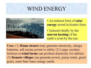
 Wind energy is indirect form of
 Solar radiation has a part in the water cycle by
 National solar radiation database
 What receives the most solar radiation
 Solar radiation
 Solar radiation
 Energy energy transfer and general energy analysis
 Energy energy transfer and general energy analysis
 Wholesale solar cell panel
 Timeline of solar energy
 Solar irradiation
 Solar energy is radiant light and heat
 Examples of electrical energy
 Avi solar energy pvt ltd
 Advancements in solar energy
 Conclusion of renewable energy
 Solar energy advantges
 Solar energy objective
 Adavantages of solar energy
 Practical application of solar energy
 Advanteges of solar energy
 Solar energy
 Pv&e
Pv&e Keva solar energy drops benefits
 References of solar energy
 Sindh solar energy project
 Natural science grade 7 term 4 notes
 Nuclear fusion solar energy
 Thermochemistry equations
 Sirindhorn international environmental park
 Energy future lines solar panelsstoragebatteries
 Benefits of solar panels australia
 Kyses
Kyses Pros and cons of electricity
 Solar energy and the atmosphere
 Advantages of geothermal energy
 Solar energy and the atmosphere
 Bhakti solar energy
 Saas architecture
 Solar energy
 Why does a good absorber of radiant energy appear black?
 Defination of biomass
 What two measurements are necessary for calculating speed
 What diagram shows surface weather measurements
 Noah's ark measurements
 Round off rule of 5
 Sig figs thermometer
 It consists of numbers representing counts or measurements
 Si unit in science
 Scientific measurements
 Forearm rom
 Qcp quality control plan
 Njrotc uniform measurements
 Wilkins score
 Pps in complete denture
 Eiffel tower equation
 Alley dock backing
 Measurements equivalents and adjustments
 Cs6250 bgp measurements
 Measurements system analysis
 Measurements system analysis
 Mathematical literacy grade 10 measurements
 Long jump measurement
 Ginger rogers measurements
 Chapter 2 measurements and calculations
 Force and torque measurements
 Ee8403 measurements and instrumentation
 Vital signs and anthropometric measurements
 Vital signs and body measurements quiz
 Measurements in chemistry
 Purchasing goals measurements
 Angle measures and segment lengths
 Galileo high accuracy service
 Cun measurements tcm
 Accuracy in measurement
 Normal vital signs
 Vital signs and anthropometric measurements
 Random errors may be detected by repeating the measurements
 Measurement topic
 Bell measurements for teleportation
 Dr katherine kuhlman measurements
 Force full gnss measurements android
 What is psp in software engineering
 What was the significance of the metric act of 1866
 Mandibular wax rim dimensions
 Mathematical literacy measurements grade 12
 Indirect method of linear measurement
 Kitchen measurements abbreviations
 Ekg wall
 Household measurements in pharmacy
 How to calculate average speed from a distance time graph
 Benchmark angle measurements
 Unit 2 measurements
 Standard model measurements
 General physics chapters
