SCHEDULE OF DIMENSIONS Schedule 1 Chapter 2 Station


- Slides: 63
SCHEDULE OF DIMENSIONS Schedule 1 Chapter 2 Station yard
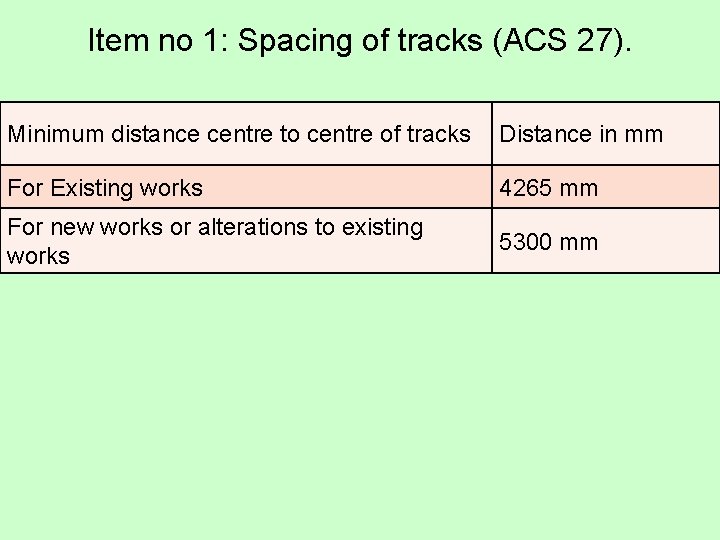
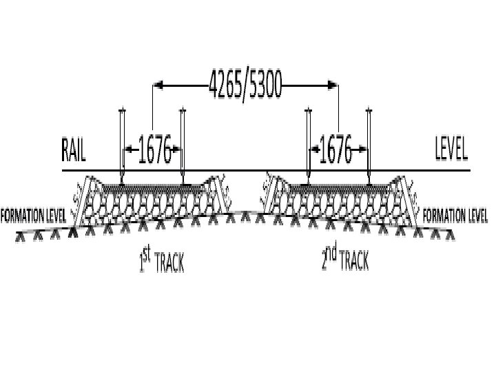
Item no 1: Spacing of tracks (ACS 27). Minimum distance centre to centre of tracks Distance in mm For Existing works 4265 mm For new works or alterations to existing works 5300 mm
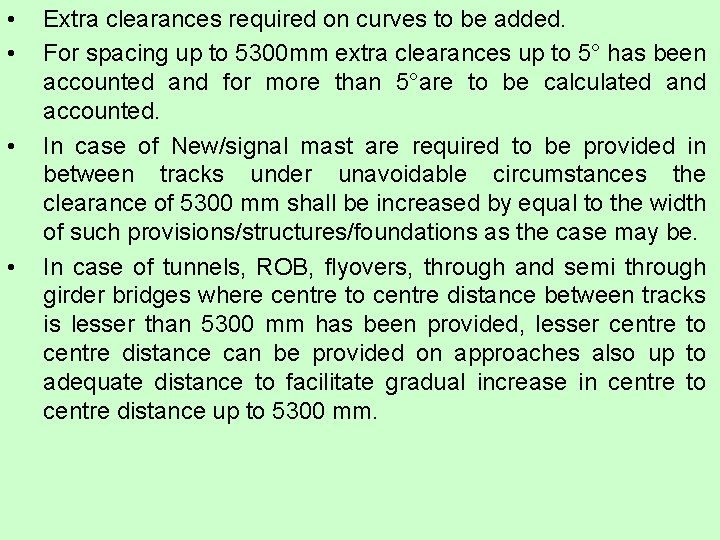
• • Extra clearances required on curves to be added. For spacing up to 5300 mm extra clearances up to 5° has been accounted and for more than 5°are to be calculated and accounted. In case of New/signal mast are required to be provided in between tracks under unavoidable circumstances the clearance of 5300 mm shall be increased by equal to the width of such provisions/structures/foundations as the case may be. In case of tunnels, ROB, flyovers, through and semi through girder bridges where centre to centre distance between tracks is lesser than 5300 mm has been provided, lesser centre to centre distance can be provided on approaches also up to adequate distance to facilitate gradual increase in centre to centre distance up to 5300 mm.
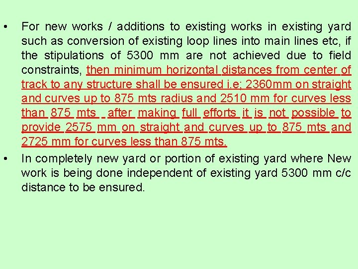
• • For new works / additions to existing works in existing yard such as conversion of existing loop lines into main lines etc, if the stipulations of 5300 mm are not achieved due to field constraints, then minimum horizontal distances from center of track to any structure shall be ensured i. e; 2360 mm on straight and curves up to 875 mts radius and 2510 mm for curves less than 875 mts after making full efforts it is not possible to provide 2575 mm on straight and curves up to 875 mts and 2725 mm for curves less than 875 mts. In completely new yard or portion of existing yard where New work is being done independent of existing yard 5300 mm c/c distance to be ensured.
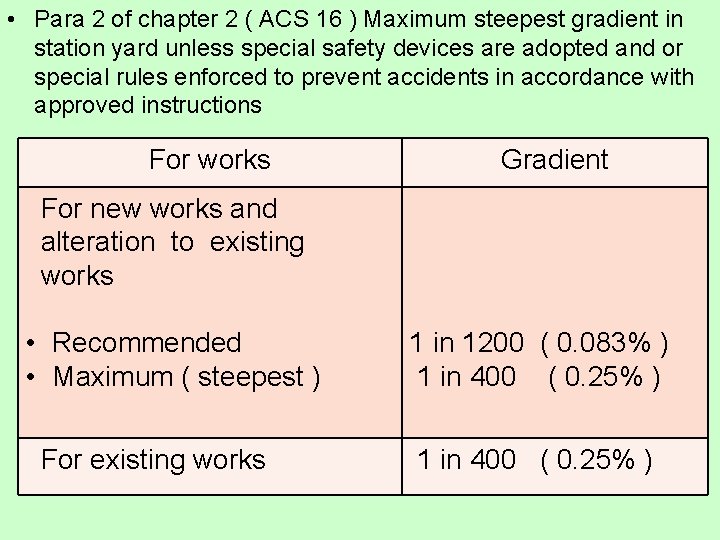
• Para 2 of chapter 2 ( ACS 16 ) Maximum steepest gradient in station yard unless special safety devices are adopted and or special rules enforced to prevent accidents in accordance with approved instructions For works Gradient For new works and alteration to existing works • Recommended • Maximum ( steepest ) For existing works 1 in 1200 ( 0. 083% ) 1 in 400 ( 0. 25% )
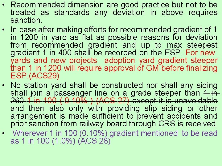
• Recommended dimension are good practice but not to be treated as standards any deviation in above requires sanction. • In case after making efforts for recommended gradient of 1 in 1200 in yard as flat as possible reasons for deviation from recommended gradient and up to max steepest gradient 1 in 400 shall be recorded on the ESP. For new yards and new projects adoption yard gradient steeper than 1 in 1200 will require approval of GM before finalizing ESP. (ACS 29) • No station yard shall be constructed nor shall any siding shall join a passenger line on a grade steeper than 1 in 260 1 in 100 ( 0. 10% ) (ACS 27) except it is unavoidable and then also only with providing slip siding or other arrangement is made sufficient to prevent accidents and prior sanction from railway board through CRS is received. • Wherever 1 in 100 (0. 10%) gradient mentioned to be read as 1 in 100 (1. 0%) (ACS 28)
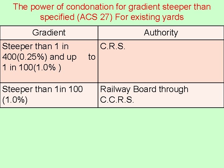
The power of condonation for gradient steeper than specified (ACS 27) For existing yards Gradient Steeper than 1 in 400(0. 25%) and up 1 in 100(1. 0% ) Steeper than 1 in 100 (1. 0%) Authority C. R. S. to Railway Board through C. C. R. S.
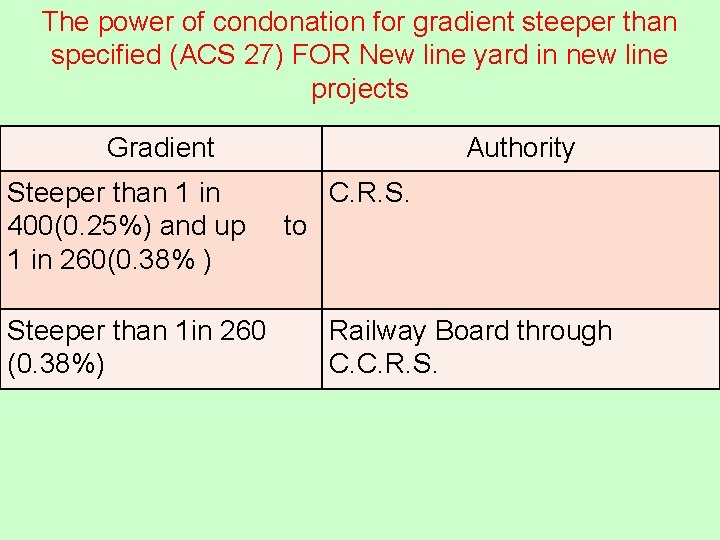
The power of condonation for gradient steeper than specified (ACS 27) FOR New line yard in new line projects Gradient Steeper than 1 in 400(0. 25%) and up 1 in 260(0. 38% ) Steeper than 1 in 260 (0. 38%) Authority C. R. S. to Railway Board through C. C. R. S.
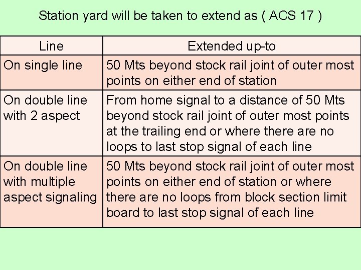
Station yard will be taken to extend as ( ACS 17 ) Line On single line Extended up-to 50 Mts beyond stock rail joint of outer most points on either end of station On double line From home signal to a distance of 50 Mts with 2 aspect beyond stock rail joint of outer most points at the trailing end or where there are no loops to last stop signal of each line On double line 50 Mts beyond stock rail joint of outer most with multiple points on either end of station or where aspect signaling there are no loops from block section limit board to last stop signal of each line
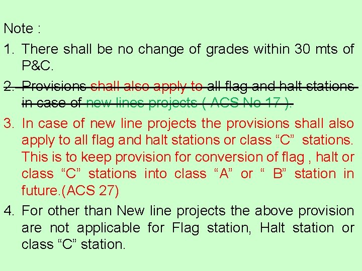
Note : 1. There shall be no change of grades within 30 mts of P&C. 2. Provisions shall also apply to all flag and halt stations in case of new lines projects ( ACS No 17 ). 3. In case of new line projects the provisions shall also apply to all flag and halt stations or class “C” stations. This is to keep provision for conversion of flag , halt or class “C” stations into class “A” or “ B” station in future. (ACS 27) 4. For other than New line projects the above provision are not applicable for Flag station, Halt station or class “C” station.
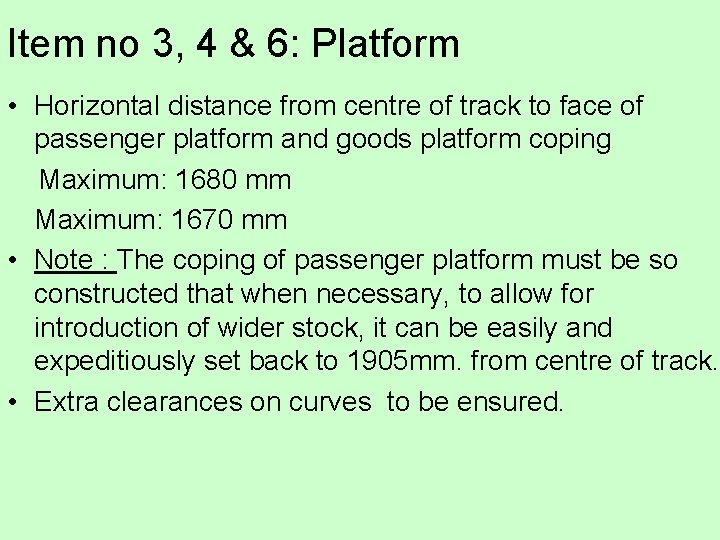
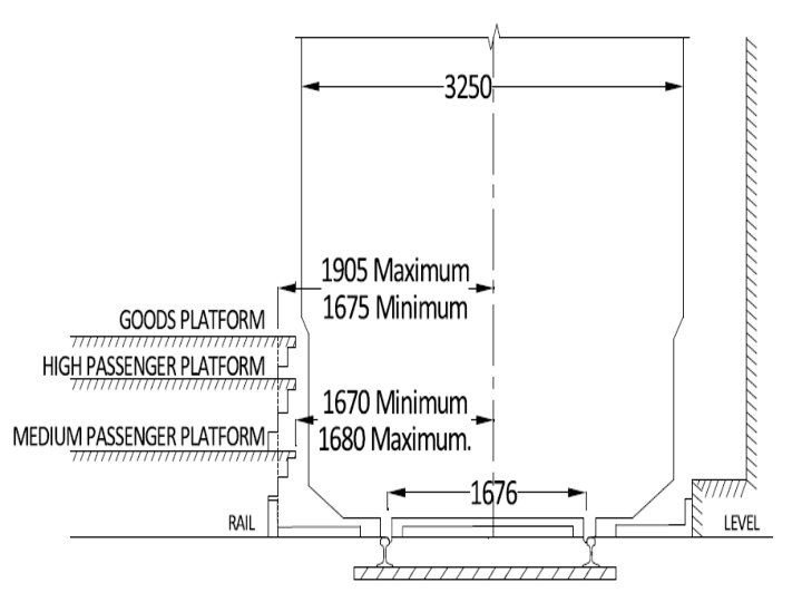
Item no 3, 4 & 6: Platform • Horizontal distance from centre of track to face of passenger platform and goods platform coping Maximum: 1680 mm Maximum: 1670 mm • Note : The coping of passenger platform must be so constructed that when necessary, to allow for introduction of wider stock, it can be easily and expeditiously set back to 1905 mm. from centre of track. • Extra clearances on curves to be ensured.
Platform • Horizontal distance from centre of track to face of any platform wall. Maximum 1905 mm Minimum 1675 mm • Note: New platform walls should be built to maximum dimensions and the coping corbelled out to 1675 mm unless provision is made to allow for the introduction of wider rolling stock either by slewing the platform track out by 230 mm or by moving the platform wall 230 mm further from the track. • Extra clearances on curves to be ensured.
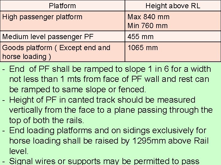
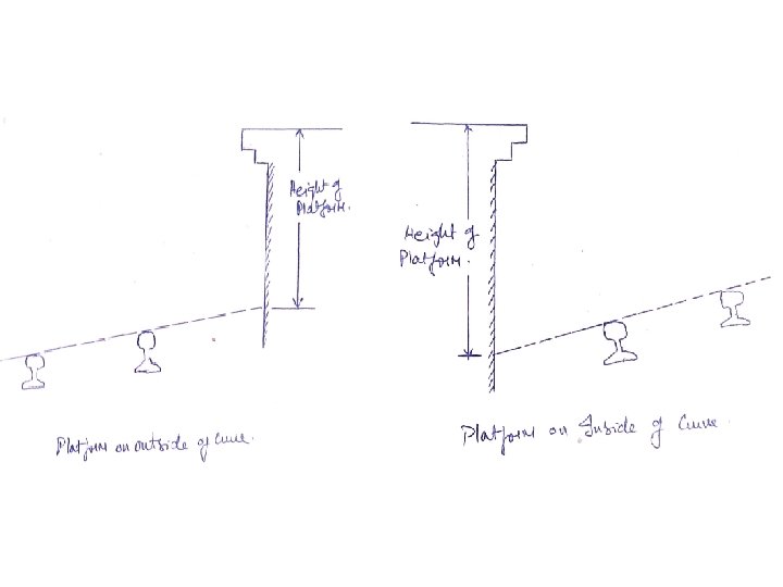
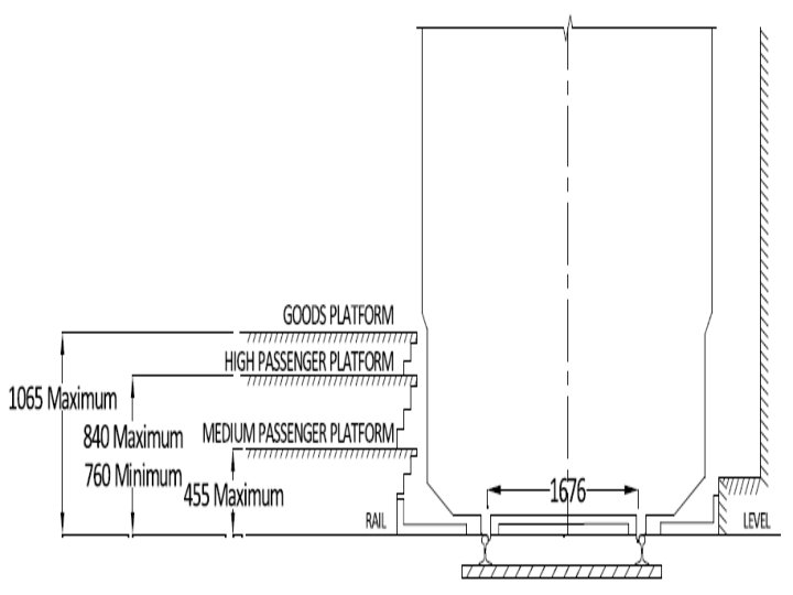
Platform High passenger platform Medium level passenger PF Goods platform ( Except end and horse loading ) Height above RL Max 840 mm Min 760 mm 455 mm 1065 mm - End of PF shall be ramped to slope 1 in 6 for a width not less than 1 mts from face of PF wall and rest can be ramped to same slope or fenced. - Height of PF in canted track should be measured vertically from the face to a plane passing through the top of both the rails. - End loading platforms and on sidings exclusively for horse loading shall be raised by 1295 mm above Rail level. - Signal wires or supports may be permitted to pass
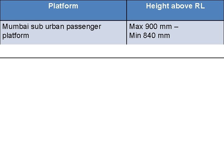
Platform Mumbai sub urban passenger platform Height above RL Max 900 mm – Min 840 mm
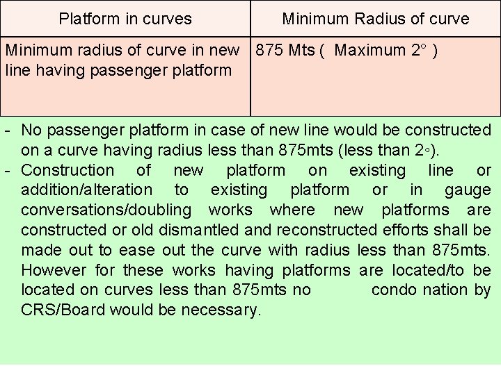
Platform in curves Minimum Radius of curve Minimum radius of curve in new 875 Mts ( Maximum 2° ) line having passenger platform - No passenger platform in case of new line would be constructed on a curve having radius less than 875 mts (less than 2◦). - Construction of new platform on existing line or addition/alteration to existing platform or in gauge conversations/doubling works where new platforms are constructed or old dismantled and reconstructed efforts shall be made out to ease out the curve with radius less than 875 mts. However for these works having platforms are located/to be located on curves less than 875 mts no condo nation by CRS/Board would be necessary.
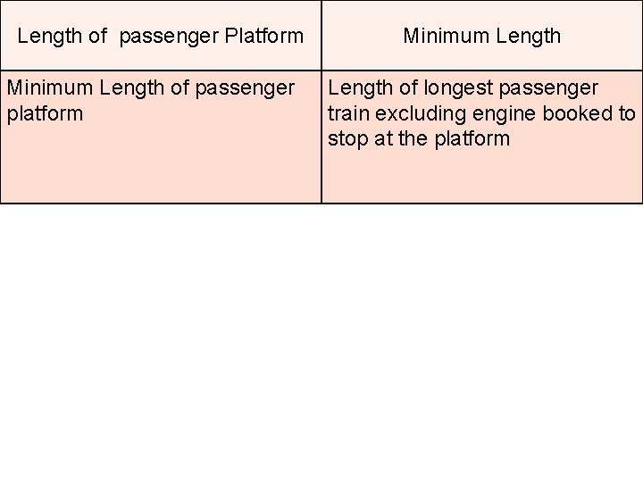
Length of passenger Platform Minimum Length of passenger platform Minimum Length of longest passenger train excluding engine booked to stop at the platform
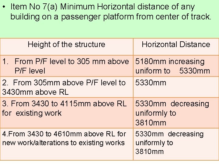
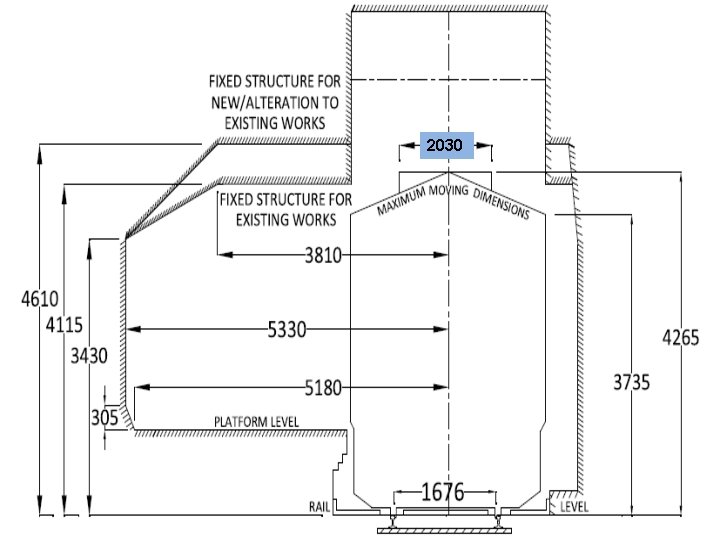
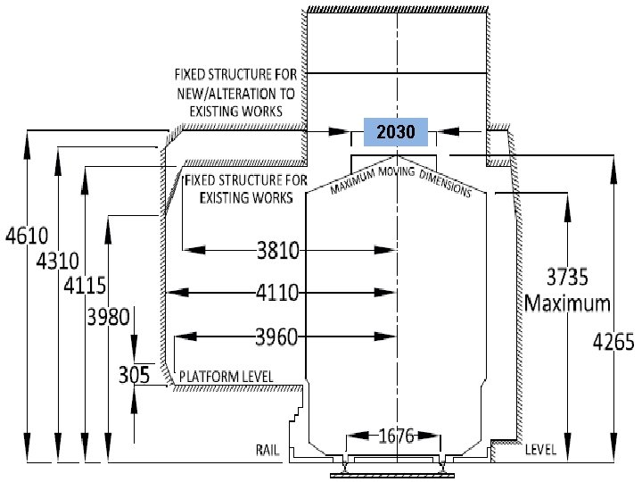
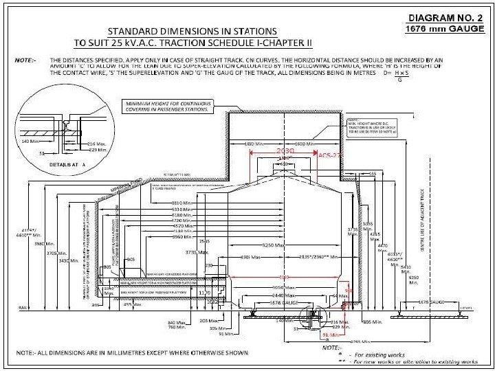
• Item No 7(a) Minimum Horizontal distance of any building on a passenger platform from center of track. Height of the structure Horizontal Distance 1. From P/F level to 305 mm above P/F level 2. From 305 mm above P/F level to 3430 mm above RL 3. From 3430 to 4115 mm above RL for existing work 5180 mm increasing uniform to 5330 mm 4. From 3430 to 4610 mm above RL for new work/alterations to existing works 5330 mm decreasing uniformly to 3810 mm
2030
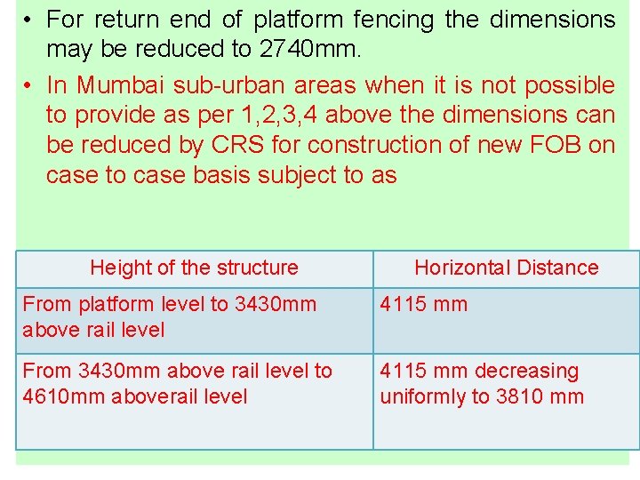
• For return end of platform fencing the dimensions may be reduced to 2740 mm. • In Mumbai sub-urban areas when it is not possible to provide as per 1, 2, 3, 4 above the dimensions can be reduced by CRS for construction of new FOB on case to case basis subject to as Height of the structure Horizontal Distance From platform level to 3430 mm above rail level 4115 mm From 3430 mm above rail level to 4610 mm aboverail level 4115 mm decreasing uniformly to 3810 mm
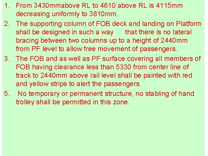
1. From 3430 mmabove RL to 4610 above RL is 4115 mm decreasing uniformly to 3810 mm. 2. The supporting column of FOB deck and landing on Platform shall be designed in such a way that there is no lateral bracing between two columns up to a height of 2440 mm from PF level to allow free movement of passengers. 3. The FOB and as well as PF surface covering all members of FOB having clearance less than 5330 from center line of track to 2440 mm above rail level shall be painted with red and yellow strips to alert the passengers. 5. No temporary or permanent structure, no stabling of hand trolley shall be permitted in this zone.
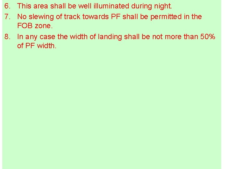
6. This area shall be well illuminated during night. 7. No slewing of track towards PF shall be permitted in the FOB zone. 8. In any case the width of landing shall be not more than 50% of PF width.
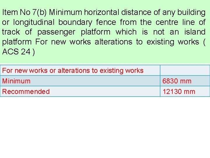
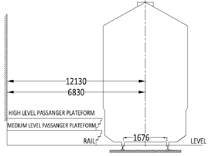
Item No 7(b) Minimum horizontal distance of any building or longitudinal boundary fence from the centre line of track of passenger platform which is not an island platform For new works alterations to existing works ( ACS 24 ) For new works or alterations to existing works Minimum Recommended 6830 mm 12130 mm
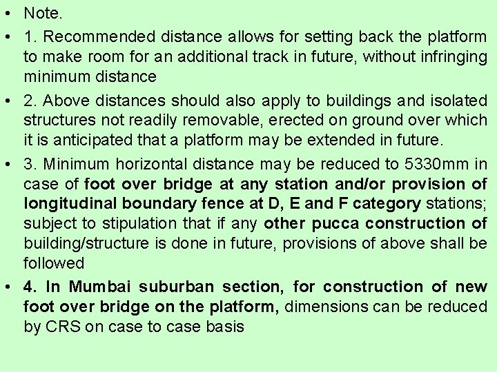
• Note. • 1. Recommended distance allows for setting back the platform to make room for an additional track in future, without infringing minimum distance • 2. Above distances should also apply to buildings and isolated structures not readily removable, erected on ground over which it is anticipated that a platform may be extended in future. • . 3. Minimum horizontal distance may be reduced to 5330 mm in case of foot over bridge at any station and/or provision of longitudinal boundary fence at D, E and F category stations; subject to stipulation that if any other pucca construction of building/structure is done in future, provisions of above shall be followed • 4. In Mumbai suburban section, for construction of new foot over bridge on the platform, dimensions can be reduced by CRS on case to case basis
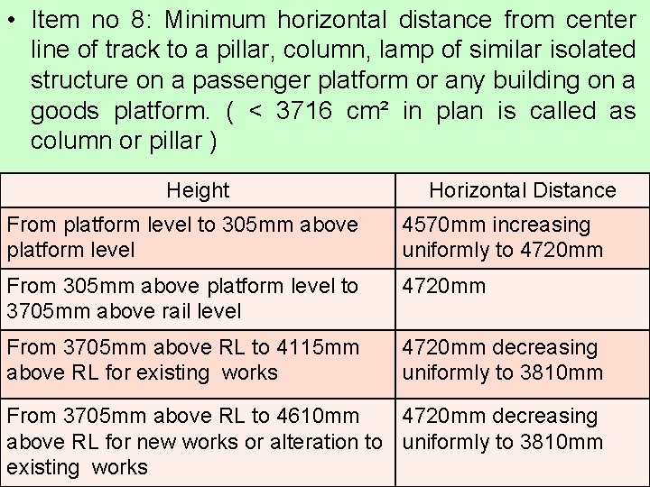
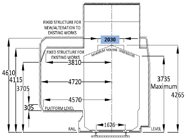
• Item no 8: Minimum horizontal distance from center line of track to a pillar, column, lamp of similar isolated structure on a passenger platform or any building on a goods platform. ( < 3716 cm² in plan is called as column or pillar ) Height Horizontal Distance From platform level to 305 mm above platform level 4570 mm increasing uniformly to 4720 mm From 305 mm above platform level to 3705 mm above rail level 4720 mm From 3705 mm above RL to 4115 mm above RL for existing works 4720 mm decreasing uniformly to 3810 mm From 3705 mm above RL to 4610 mm 4720 mm decreasing above RL for new works or alteration to uniformly to 3810 mm existing works
2030
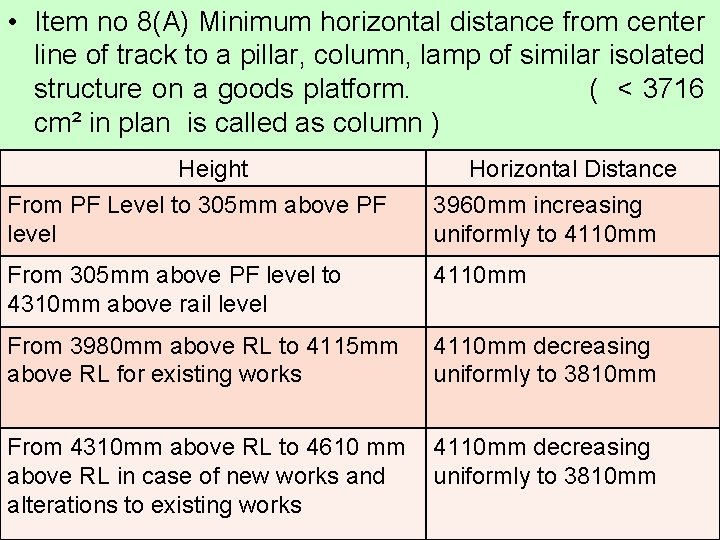
• Item no 8(A) Minimum horizontal distance from center line of track to a pillar, column, lamp of similar isolated structure on a goods platform. ( < 3716 cm² in plan is called as column ) Height Horizontal Distance From PF Level to 305 mm above PF level 3960 mm increasing uniformly to 4110 mm From 305 mm above PF level to 4310 mm above rail level 4110 mm From 3980 mm above RL to 4115 mm above RL for existing works 4110 mm decreasing uniformly to 3810 mm From 4310 mm above RL to 4610 mm above RL in case of new works and alterations to existing works 4110 mm decreasing uniformly to 3810 mm
2030
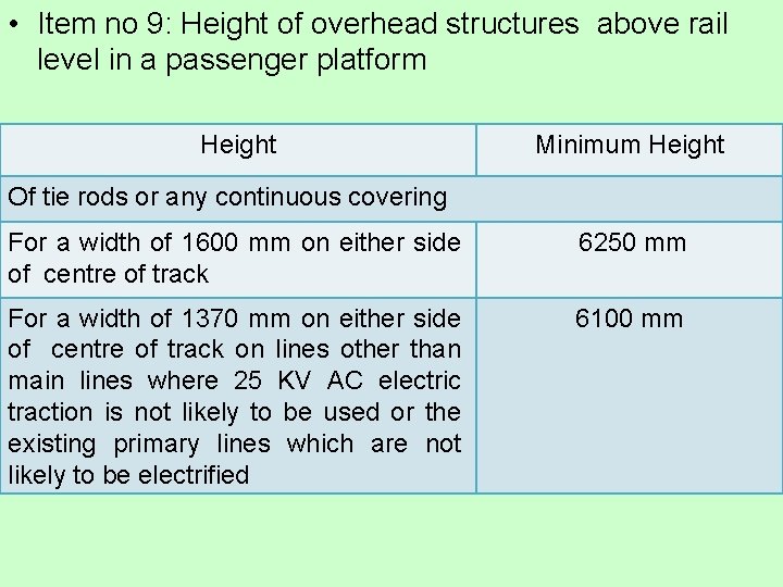
• Item no 9: Height of overhead structures above rail level in a passenger platform Height Minimum Height Of tie rods or any continuous covering For a width of 1600 mm on either side of centre of track 6250 mm For a width of 1370 mm on either side of centre of track on lines other than main lines where 25 KV AC electric traction is not likely to be used or the existing primary lines which are not likely to be electrified 6100 mm
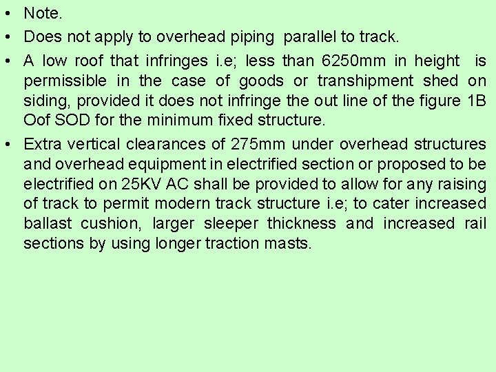
• Note. • Does not apply to overhead piping parallel to track. • A low roof that infringes i. e; less than 6250 mm in height is permissible in the case of goods or transhipment shed on siding, provided it does not infringe the out line of the figure 1 B Oof SOD for the minimum fixed structure. • Extra vertical clearances of 275 mm under overhead structures. and overhead equipment in electrified section or proposed to be electrified on 25 KV AC shall be provided to allow for any raising of track to permit modern track structure i. e; to cater increased ballast cushion, larger sleeper thickness and increased rail sections by using longer traction masts.
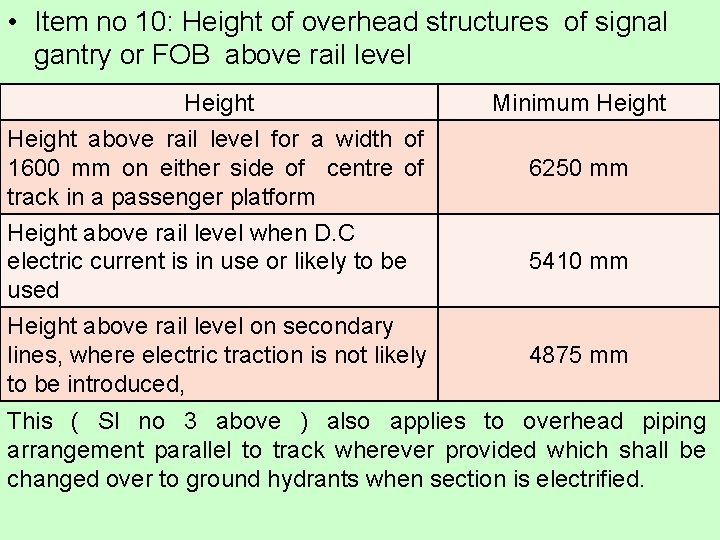
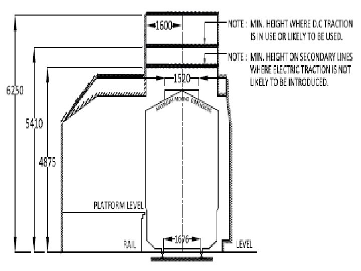
• Item no 10: Height of overhead structures of signal gantry or FOB above rail level Height Minimum Height above rail level for a width of 1600 mm on either side of centre of track in a passenger platform 6250 mm Height above rail level when D. C electric current is in use or likely to be used 5410 mm Height above rail level on secondary lines, where electric traction is not likely to be introduced, 4875 mm This ( Sl no 3 above ) also applies to overhead piping arrangement parallel to track wherever provided which shall be changed over to ground hydrants when section is electrified.
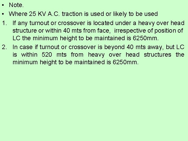
• Note. • Where 25 KV A. C. traction is used or likely to be used 1. If any turnout or crossover is located under a heavy over head structure or within 40 mts from face, irrespective of position of LC the minimum height to be maintained is 6250 mm. 2. In case if turnout or crossover is beyond 40 mts away, but LC is within 520 mts from heavy over head structures the minimum height to be maintained is 6250 mm. .
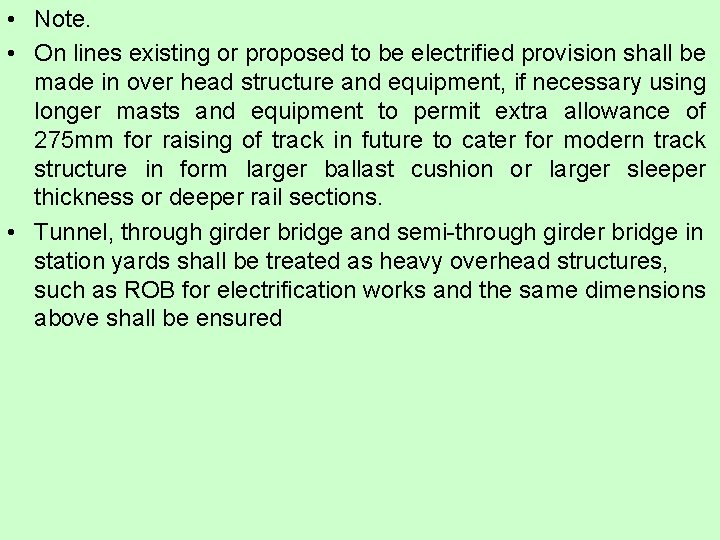
• Note. • On lines existing or proposed to be electrified provision shall be made in over head structure and equipment, if necessary using longer masts and equipment to permit extra allowance of 275 mm for raising of track in future to cater for modern track structure in form larger ballast cushion or larger sleeper thickness or deeper rail sections. • . Tunnel, through girder bridge and semi-through girder bridge in station yards shall be treated as heavy overhead structures, such as ROB for electrification works and the same dimensions above shall be ensured
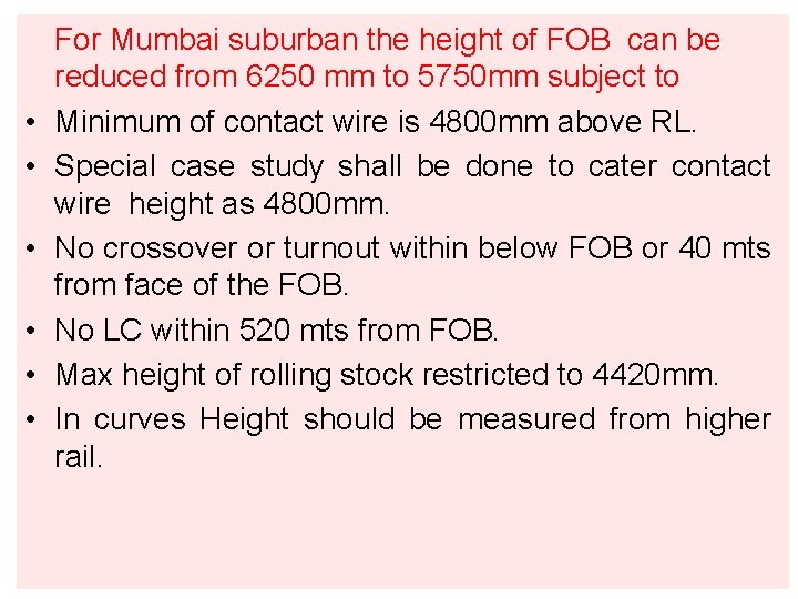
• • • For Mumbai suburban the height of FOB can be reduced from 6250 mm to 5750 mm subject to Minimum of contact wire is 4800 mm above RL. Special case study shall be done to cater contact wire height as 4800 mm. No crossover or turnout within below FOB or 40 mts from face of the FOB. No LC within 520 mts from FOB. Max height of rolling stock restricted to 4420 mm. In curves Height should be measured from higher rail.
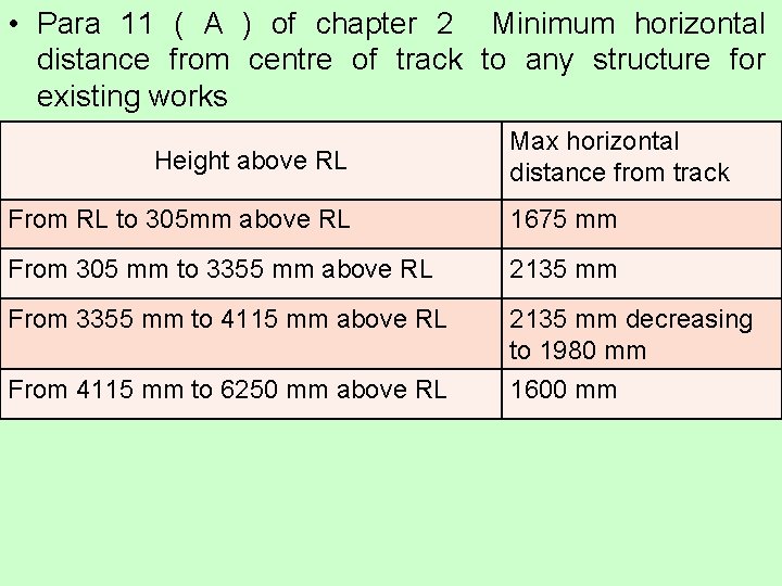
• Para 11 ( A ) of chapter 2 Minimum horizontal distance from centre of track to any structure for existing works Height above RL Max horizontal distance from track From RL to 305 mm above RL 1675 mm From 305 mm to 3355 mm above RL 2135 mm From 3355 mm to 4115 mm above RL 2135 mm decreasing to 1980 mm 1600 mm From 4115 mm to 6250 mm above RL
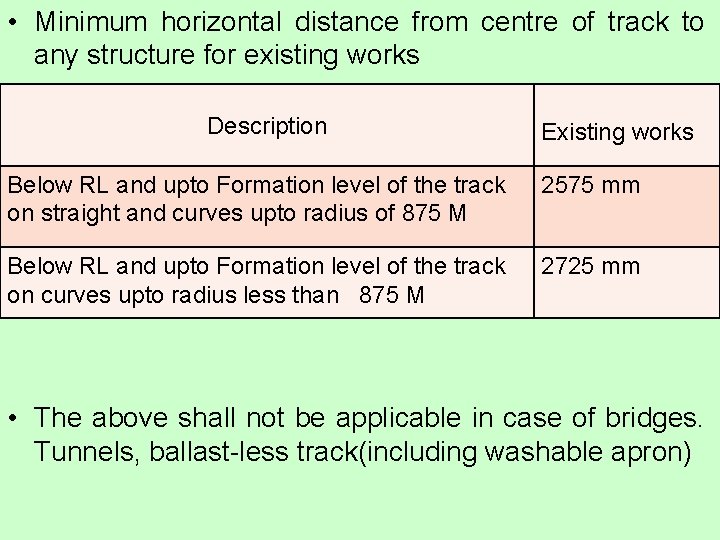
• Minimum horizontal distance from centre of track to any structure for existing works Description Existing works Below RL and upto Formation level of the track on straight and curves upto radius of 875 M 2575 mm Below RL and upto Formation level of the track on curves upto radius less than 875 M 2725 mm • The above shall not be applicable in case of bridges. Tunnels, ballast-less track(including washable apron)
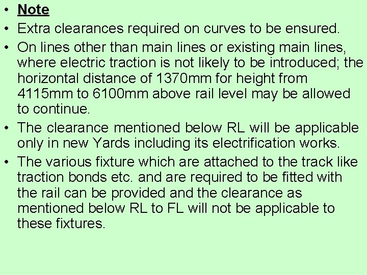
• Note • Extra clearances required on curves to be ensured. • On lines other than main lines or existing main lines, where electric traction is not likely to be introduced; the horizontal distance of 1370 mm for height from 4115 mm to 6100 mm above rail level may be allowed to continue. • The clearance mentioned below RL will be applicable only in new Yards including its electrification works. • The various fixture which are attached to the track like traction bonds etc. and are required to be fitted with the rail can be provided and the clearance as mentioned below RL to FL will not be applicable to these fixtures.
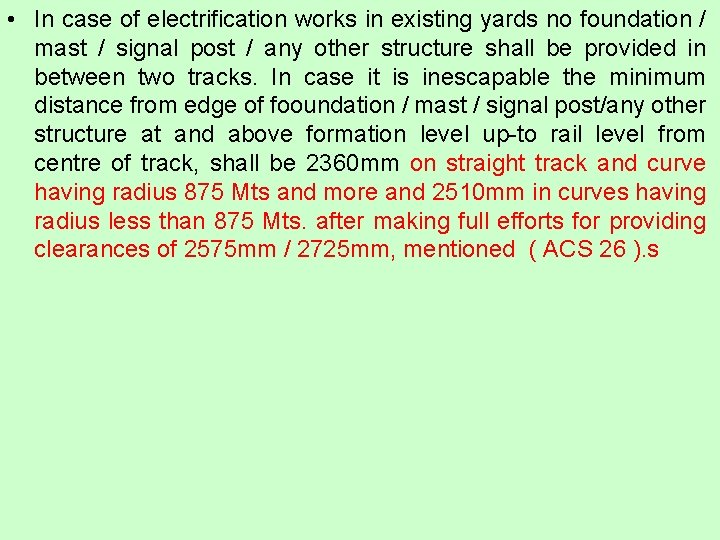
• In case of electrification works in existing yards no foundation / mast / signal post / any other structure shall be provided in between two tracks. In case it is inescapable the minimum distance from edge of fooundation / mast / signal post/any other structure at and above formation level up-to rail level from centre of track, shall be 2360 mm on straight track and curve having radius 875 Mts and more and 2510 mm in curves having radius less than 875 Mts. after making full efforts for providing clearances of 2575 mm / 2725 mm, mentioned ( ACS 26 ). s
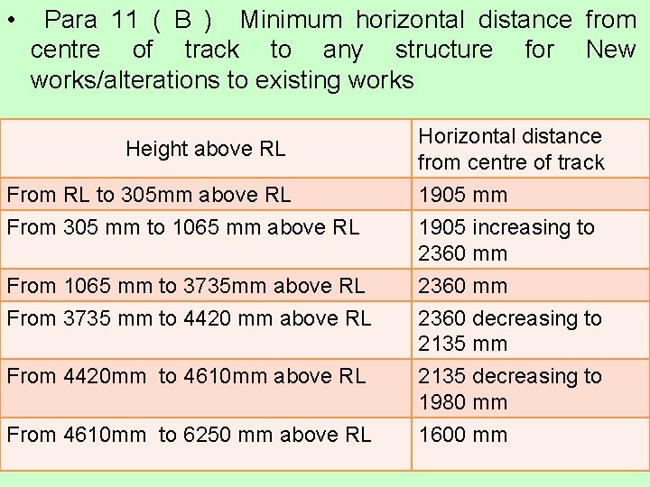
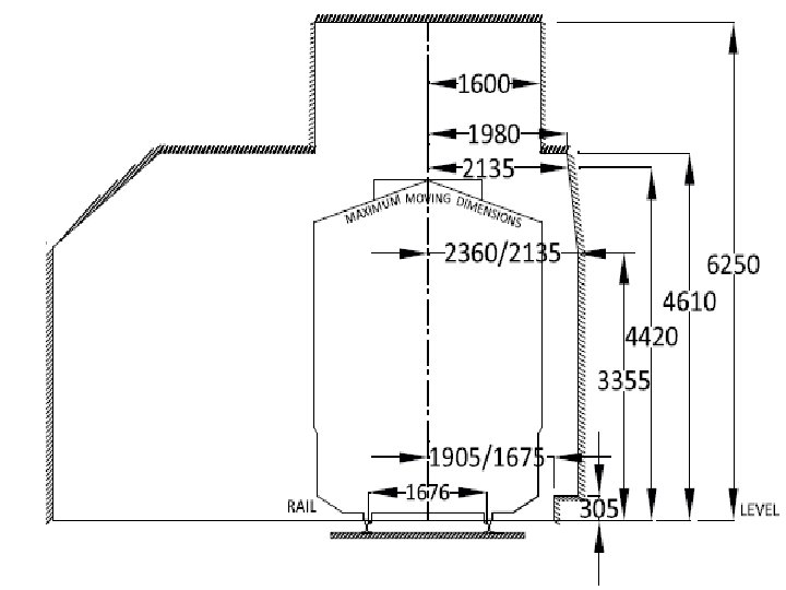
• Para 11 ( B ) Minimum horizontal distance from centre of track to any structure for New works/alterations to existing works Height above RL Horizontal distance from centre of track From RL to 305 mm above RL From 305 mm to 1065 mm above RL 1905 mm 1905 increasing to 2360 mm From 1065 mm to 3735 mm above RL From 3735 mm to 4420 mm above RL 2360 mm 2360 decreasing to 2135 mm 2135 decreasing to 1980 mm 1600 mm From 4420 mm to 4610 mm above RL From 4610 mm to 6250 mm above RL
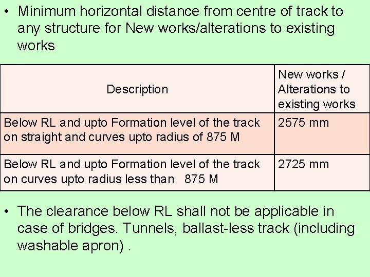
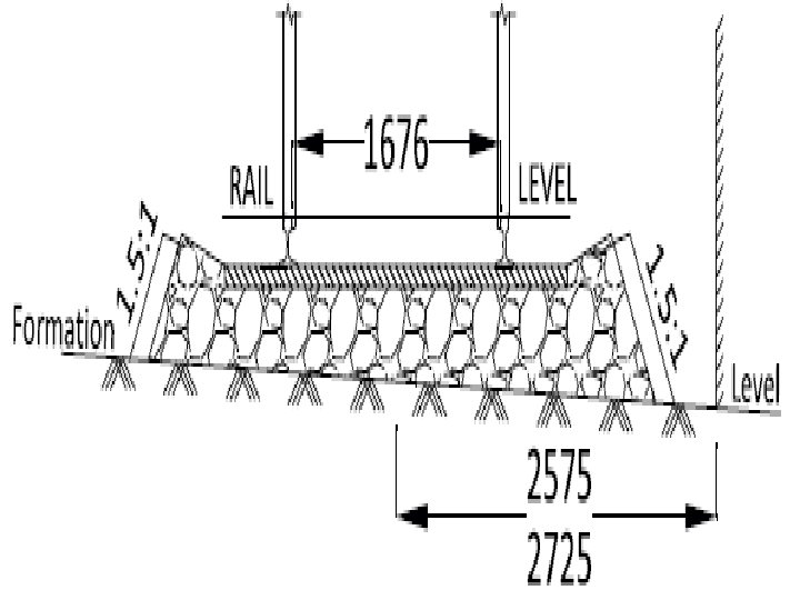
• Minimum horizontal distance from centre of track to any structure for New works/alterations to existing works Description Below RL and upto Formation level of the track on straight and curves upto radius of 875 M Below RL and upto Formation level of the track on curves upto radius less than 875 M New works / Alterations to existing works 2575 mm 2725 mm • The clearance below RL shall not be applicable in case of bridges. Tunnels, ballast-less track (including washable apron).
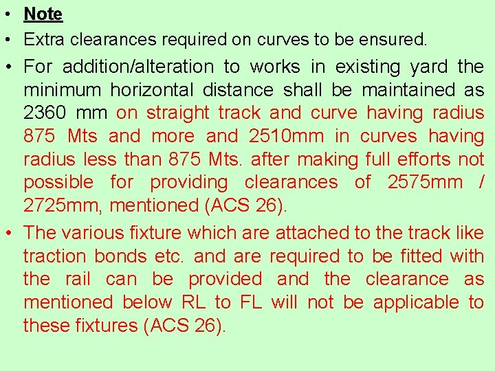
• Note • Extra clearances required on curves to be ensured. • For addition/alteration to works in existing yard the minimum horizontal distance shall be maintained as 2360 mm on straight track and curve having radius 875 Mts and more and 2510 mm in curves having radius less than 875 Mts. after making full efforts not possible for providing clearances of 2575 mm / 2725 mm, mentioned (ACS 26). • The various fixture which are attached to the track like traction bonds etc. and are required to be fitted with the rail can be provided and the clearance as mentioned below RL to FL will not be applicable to these fixtures (ACS 26).
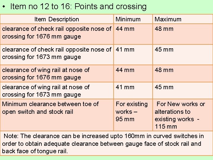
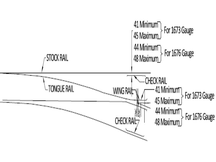
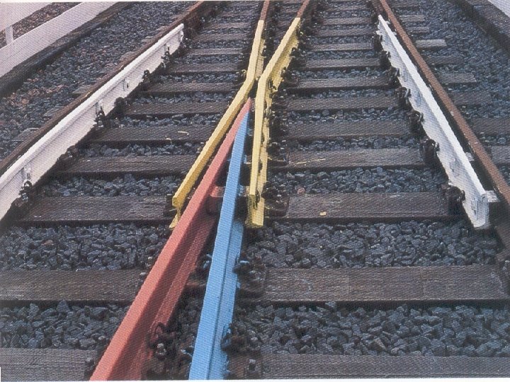
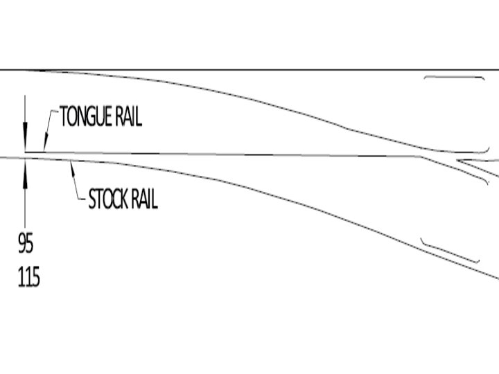
• Item no 12 to 16: Points and crossing Item Description Minimum Maximum clearance of check rail opposite nose of 44 mm crossing for 1676 mm gauge 48 mm clearance of check rail opposite nose of 41 mm crossing for 1673 mm gauge 45 mm clearance of wing rail at nose of crossing for 1676 mm gauge 44 mm 48 mm clearance of wing rail at nose of crossing for 1673 mm gauge 41 mm 45 mm Minimum clearance between toe of open switch and stock rail For existing works – 95 mm For New works or alterations to existing works 115 mm Note: The clearance can be increased upto 160 mm in curved switches in order to obtain adequate clearance between gauge face of stock rail and back face of tongue rail.
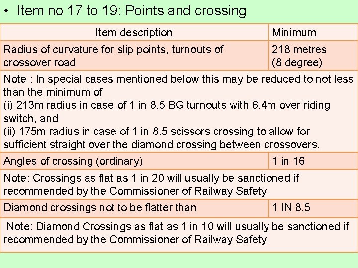
• Item no 17 to 19: Points and crossing Item description Radius of curvature for slip points, turnouts of crossover road Minimum 218 metres (8 degree) Note : In special cases mentioned below this may be reduced to not less than the minimum of (i) 213 m radius in case of 1 in 8. 5 BG turnouts with 6. 4 m over riding switch, and (ii) 175 m radius in case of 1 in 8. 5 scissors crossing to allow for sufficient straight over the diamond crossing between crossovers. Angles of crossing (ordinary) 1 in 16 Note: Crossings as flat as 1 in 20 will usually be sanctioned if recommended by the Commissioner of Railway Safety. Diamond crossings not to be flatter than 1 IN 8. 5 Note: Diamond Crossings as flat as 1 in 10 will usually be sanctioned if recommended by the Commissioner of Railway Safety.
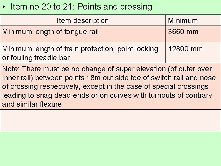
• Item no 20 to 21: Points and crossing Item description Minimum length of tongue rail Minimum 3660 mm Minimum length of train protection, point locking or fouling treadle bar 12800 mm Note: There must be no change of super elevation (of outer over inner rail) between points 18 m out side toe of switch rail and nose of crossing respectively, except in the case of special crossings leading to snag dead-ends or on curves with turnouts of contrary and similar flexure
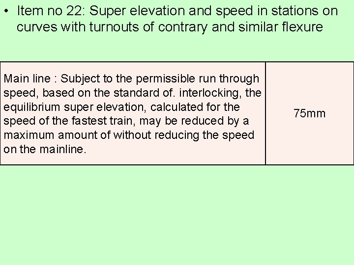
• Item no 22: Super elevation and speed in stations on curves with turnouts of contrary and similar flexure Main line : Subject to the permissible run through speed, based on the standard of. interlocking, the equilibrium super elevation, calculated for the speed of the fastest train, may be reduced by a maximum amount of without reducing the speed on the mainline. 75 mm
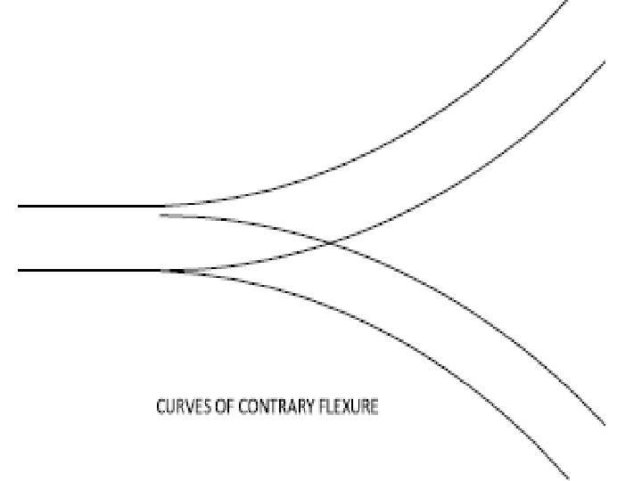
• Curves of contrary flexure • Permissible negative cant on turnout ( which is also the actual cant on main line ) is 75 – C where C = GV² / 127 R C = Actual cant on turnout in mm G = Dynamic gauge in mm V = Design speed on turnout in KMPH R = Radius of turnout in mts.
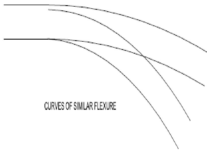
• Curves of similar flexure • In the case of a reverse curve close behind the crossing of the turnouts, the super elevation may be run out at the maximum of 1 mm in 360 mm (2. 77 mm/mts)
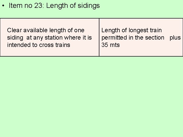
• Item no 23: Length of sidings Clear available length of one siding at any station where it is intended to cross trains Length of longest train permitted in the section plus 35 mts
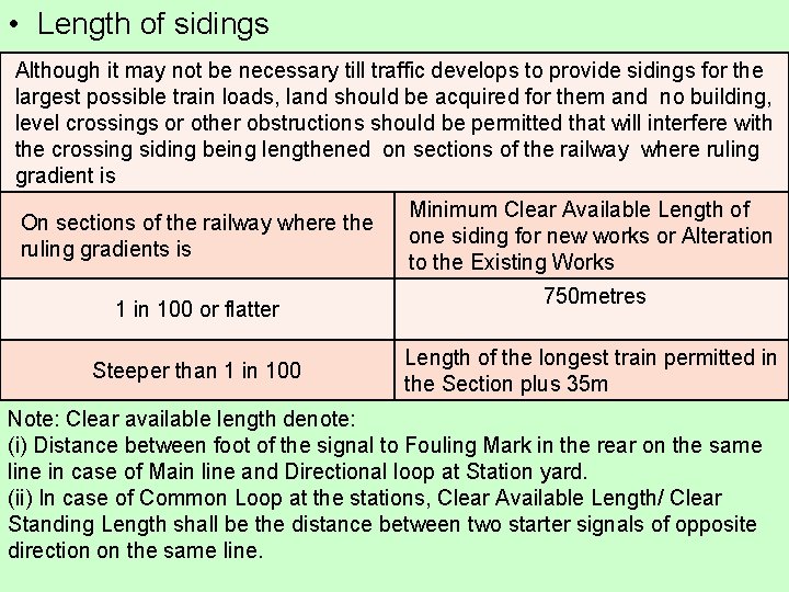
• Length of sidings Although it may not be necessary till traffic develops to provide sidings for the largest possible train loads, land should be acquired for them and no building, level crossings or other obstructions should be permitted that will interfere with the crossing siding being lengthened on sections of the railway where ruling gradient is On sections of the railway where the ruling gradients is 1 in 100 or flatter Steeper than 1 in 100 Minimum Clear Available Length of one siding for new works or Alteration to the Existing Works 750 metres Length of the longest train permitted in the Section plus 35 m Note: Clear available length denote: (i) Distance between foot of the signal to Fouling Mark in the rear on the same line in case of Main line and Directional loop at Station yard. (ii) In case of Common Loop at the stations, Clear Available Length/ Clear Standing Length shall be the distance between two starter signals of opposite direction on the same line.
Thank you