EARTH SEGMENT SPACE LINK Unit 3 Earth segment


 system is used to")


- Slides: 21
EARTH SEGMENT & SPACE LINK Unit 3
Earth segment • Introduction • Receive-Only Home TV Systems – Outdoor Unit – Indoor Unit for Analog (FM) TV • Master Antenna TV System • Community Antenna TV System • Transmit-Receive Earth Stations
• A home terminal for DBS TV/FM reception • The LNB provides gain for the broadband 12 -GHz signal Converts the signal to a lower frequency range so that a low-cost coaxial cable can be used as feeder to the indoor unit. The reflector diameter for 4 -GHz reception is typically about 3 m
Master Antenna TV System • A master antenna TV (MATV) system is used to provide reception of DBS TV/FM channels to a small group of users • It consists of a single outdoor unit (antenna and LNA/C) feeding a number of indoor units
Master Antenna TV System It consists of a single outdoor unit feeding a number of indoor units
Community Antenna TV System Instead of having a separate receiver for each user, all the carriers are demodulated in a common receiver-filter system The channels are then combined into a standard multiplexed signal for transmission over cable to the subscribers
Transmit-Receive Earth Stations • In some situations, a transmit-only station is required • For example, – in relaying TV signals to the remote TV receiveonly stations • Transmit-receive stations provide both functions
Transmit-Receive Earth Stations
More detailed block diagram of a transmit-receive earth station
Traffic • Traffic can be broadly classified as – heavy route, – medium route, and – thin route. • In a thin-route circuit, a transponder channel (36 MHz) may be occupied by a number of single carriers, each associated with its own voice circuit. • This mode of operation is known as single carrier per channel (SCPC) • Antenna sizes range from 3. 6 m (11. 8 ft) for transportable stations up to 30 m (98. 4 ft) for a main terminal.
Medium route • A medium-route circuit also provides multiple access, either on the basis of – frequency-division multiple access (FDMA) or – time-division multiple access (TDMA), • Antenna sizes range from 30 m (89. 4 ft) for a main station to 10 m (32. 8 ft) for a remote station.
Heavy route • In a 6/4 -GHz heavy-route system, – each satellite channel (bandwidth 36 MHz) is capable of carrying over 960 one-way voice circuits simultaneously or – a single-color analog TV signal with associated audio • Thus the transponder channel for a heavy-route circuit carries one large-bandwidth signal which may be TV or multiplexed telephony. • The antenna diameter for a heavy-route circuit is at least 30 m (98. 4 ft).
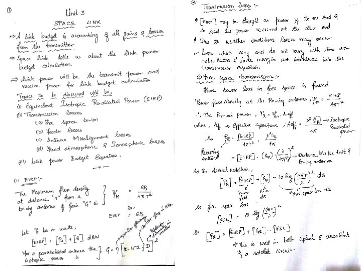
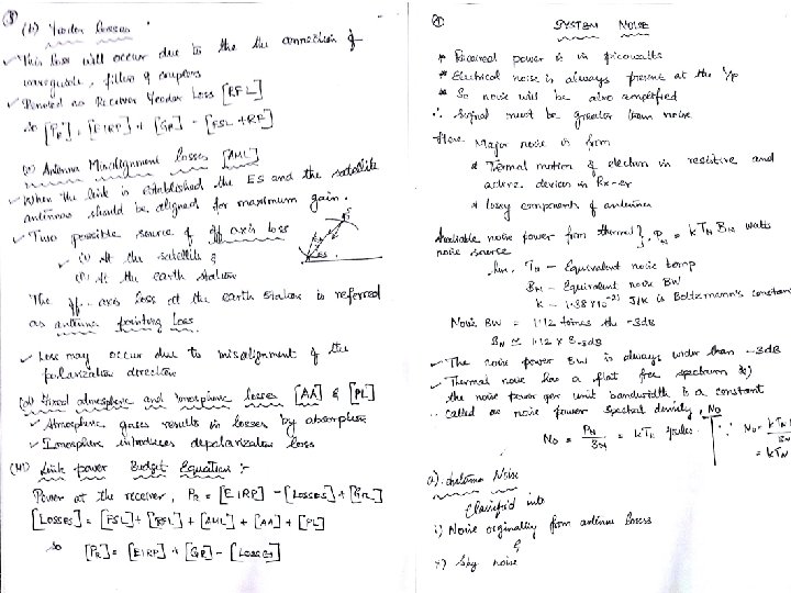
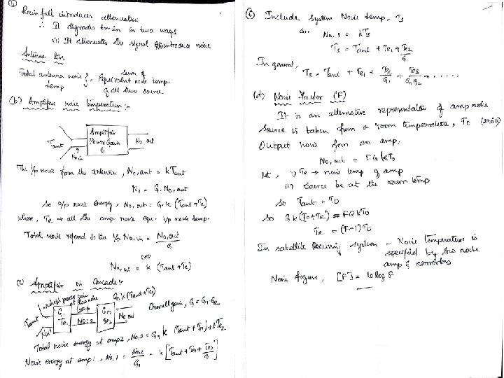
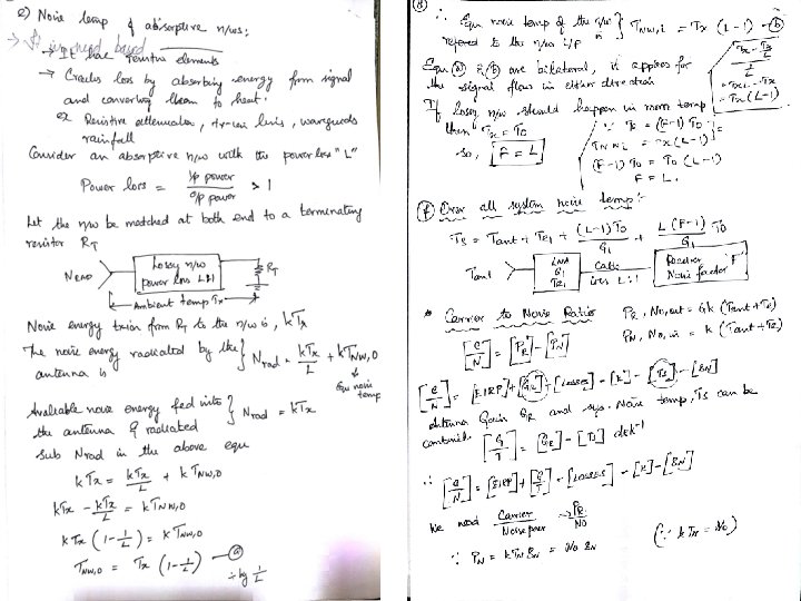
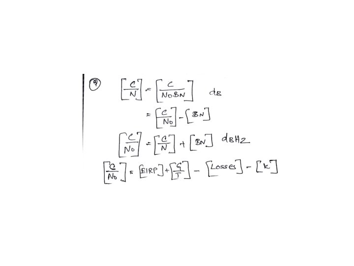
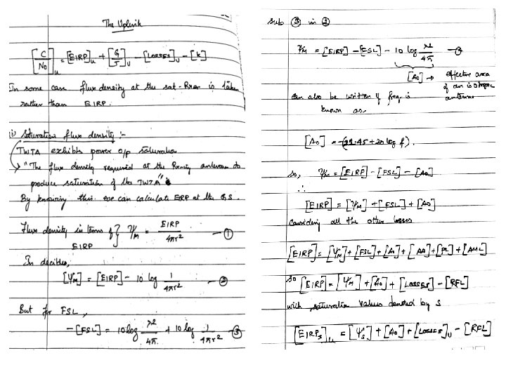
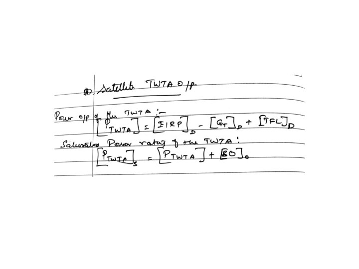
Space link • • • • Equivalent Isotropic Radiated Power Transmission Losses Free-Space Transmission Feeder Losses Antenna Misalignment Losses Fixed Atmospheric and Ionospheric Losses Link Power Budget Equation System Noise Antenna Noise Amplifier Noise Temperature Amplifiers in Cascade Noise Factor Noise Temperature of Absorptive Networks Overall System Noise Temperature Carrier-to-Noise Ratio Uplink Saturation Flux Density Input Back Off The Earth Station HPA Downlink Output Back off Satellite TWTA Output Effects of Rain Uplink rain-fade margin Downlink rain-fade margin Combined Uplink and Downlink C/N Ratio • Intermodulation Noise. • • •
ddc