SCHEDULE OF DIMENSIONS PRESENTED BY N R KALELecturer
")
SCHEDULE OF DIMENSIONS PRESENTED BY N. R. KALE/Lecturer (works)

What is SOD ? Schedule of dimension is nothing but a schedule, which lays down : n Limiting values, recommended values, and infringement to limiting values, which can be continued over entire Indian railways system for various track parameters. n Goods wagon and coaching stock parameters. n Horizontal and vertical clearances to be followed on Indian railways. n

Necessity of S O D It is absolutely essential to ensure safety of traveling public as well as goods over entire Indian railways system. n To adopt uniform system of track tolerances, location of structures and construction standard all over the Indian railways. n To permit different types of coaching and goods stock owned by different railways to ply on entire railway system with same level of degree of safety. n

Brief Introduction n n 1913 - First schedule of maxm & minm dimension. 1922 – SOD with Maxm. Minm & recommended dimension was published. 1929 – Amendment in order to introduce some improvement and additions of clearances required for electric traction. 1936 – Financial stringency on railway therefore amendment to restrict capital expenditure to minimum.

Contd. …. 1939 & 1958 reprinted with some modifications. n 1973 – Reprinted with conversion to metric system, introduction of dimensions for 25 KV AC traction. n 1990 – Recommendations of 64 th Track Standard Committee for revision of SOD of 1939 reprinted in 1973. n 2004 – Revised version published with some modifications. n

MAIN FEATURES OF SOD-2004 Dimensions are given only for 1676 mm gauge. v Consists of only metric units. v Only two schedules – schedule I & schedule II v Extra clearances required for curves are modified to suit speed of 160 kmph and SE of 165 mm v Additional appendix for extra clearances required for 200 kmph is also given with 185 mm SE v

SCHEDULE - I Schedule I of SOD-2004 consists of those items which are mandatory and have to be observed on all 1676 mm gauge Railways in India. n Contains the items of Schedule- I and certain selected items of Schedule- II of 1973 Version n

Contd. … DIMENSIONS given in Schedule-I are classified under two heads : ‘Existing works’ – The works which were existing before issue of SOD ( 2004 ). ‘New works’ – Include new constructions, additions of new lines/structure, gauge conversion and doubling

Contd. … However following works will not be included in ‘New works’Shifting of Points & Crossings. Extension of siding. Extension of building, etc.

SCHEDULE - II n Schedule – II contains the existing infringements of Schedule – I. n These are items, which were included in Schedule – III of 1973 version.
 ESSENTIAL FOR SAFETY ii) PRIOR")
CONTENT OF S. O. D. SCHEDULE I : -i) ESSENTIAL FOR SAFETY ii) PRIOR SANCTION FOR DEVIATION CHAPTER DETAILS I GENERAL Spacing, , Curves, Br. Bldg Structure, Tunnel, Sig Gear, locking etc. II. STN YARD Pts. & Crossing, P/F, Bldg/St, Tr. Spacing etc.
 Rolling stock (C&W) Tr, Spacing, O/Head")
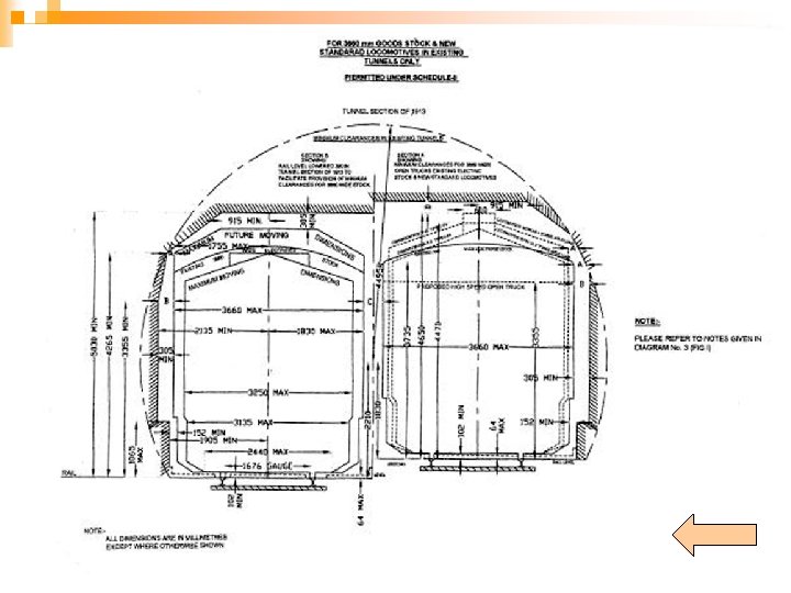
Contd. … III –W/Shop & Sheds IV –(A) Rolling stock (C&W) Tr, Spacing, O/Head Girder Structure. Wheels /Axles, Wheelbase, Buffers / Couplings, Floor height Max. moving dimensions IV-(B)- Rolling Max. future moving Stock (3660 mm) - dimensions.
 Wheels & Axles, Buffers/ Couplings, Max. moving Dimensions. V-ELECT.")
Contd. … IV-©-Rolling Stock (Loco) Wheels & Axles, Buffers/ Couplings, Max. moving Dimensions. V-ELECT. TR. (D. C. ) Elect. Equipment Clearances. V-(A)-----(A. C. ) -------DO------

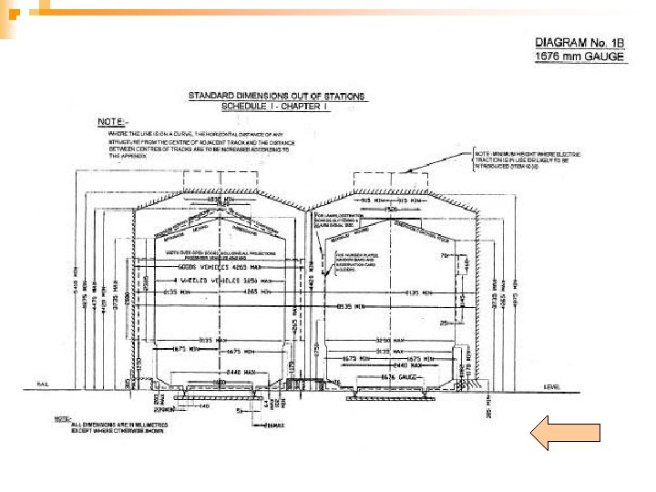
SCHEDULE I CHAPTER I MIN. DIST. C/C OF TRACK. As per CS No. 9 dated. 16. 10. 2012 i) For existing works 4265 mm ii) For new works/additions to existing works 5300 mm Note: OHE mast and Signal post shall not n preferably be provided in between tracks. However, under unavoidable circumstances, the clearance shall be increased by equal to width of such structure/foundation.
 As")
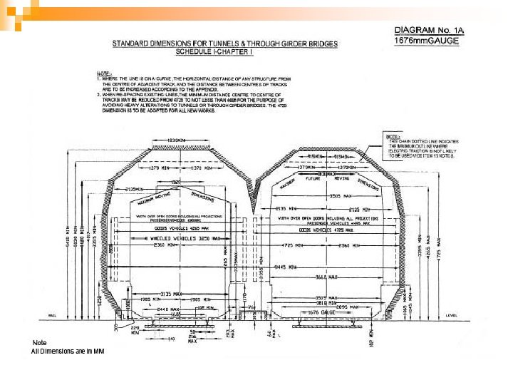
SCHEDULE I CHAPTER I MIN. DIST. C/C OF TRACK (Tunnel, Semi-through/Through girder bridges) As per CS No. 9 dated. 16. 10. 2012 i) For existing works 4495 mm ii) For new works/additions to existing works 4725 mm n
 Note: Check rails")
Contd. … n Minimum Radius of curves -175 m (10 degree) Note: Check rails to be provided in curves having radius 218 meters(8 degree) and sharper. Check rails may also be provided in flatter curves, if high speed is contemplated.
 Maximum clear distance bet. two sleepers on bridge: i) on existing")
Contd. … A) Maximum clear distance bet. two sleepers on bridge: i) on existing Bridges 510 mm ii) New construction & on existing bridges 450 mm during regirdering /TSR B) Maximum distance between Joint sleepers on Bridges. 200 mm

Contd. … Minimum thickness 150 mm of Bridge timber, exclusive of notching. Minimum length of 305 mm + dist. (subject to bridge sleeper. from out side min. 2440 to outside of mm) girder flange

SCHEDULE I CHAPTER I CONTD… n Minimum clearance of check rail on curve. n Minimum clearance of check rail on level crossing. n Maximum clearance of check rail on level crossing. n Minimum depth for wheel flange. 44 mm. 51 mm. 57 mm 38 mm

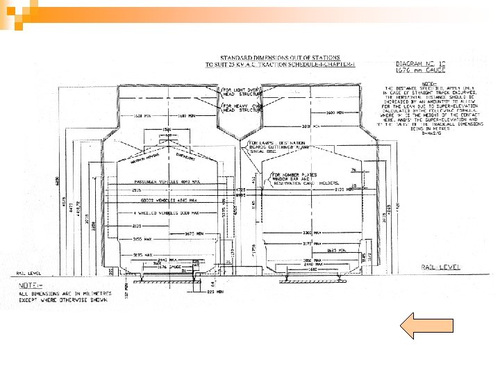
Schedule I chapter I contd. … BULDING AND STRUCTURE Minimum horizontal distance from center of track to any structure from RL to 305 mm above RL i) For existing works 1675 mm ii) For new works or alterations to existing works 1905 mm
For")
Minimum horizontal distance from C/L of track to any structure except a platform. i)For existing works. 2135 mm From 305 mm to 4420 mm above RL. ii) For new works or alterations 1905 mm to new works increasing to From 305 mm to 1065 mm 2360 mm above R L From 1065 mm to 3355 mm 2360 mm

Contd. … From 3355 to 4420 mm above rail level 2360 mm decreasing to 2135 mm From 4420 to 5870 mm above rail level 2135 mm decreasing to 915 mm

Contd. … Below the rail level up to the formation level on the straight track and curve up to 875 m 2575 mm Below the rail level up to the formation level on the curve Radius< 875 m 2725 mm

Schedule I Chapter I contd. … Minimum horizontal distance of any telegraph post from C/L of nearest track i) ii) For existing works For new works - Ht of the post + 2135 mm. Ht of the post + 2360 mm.
 Min. ht. above rail level")
Height of ROB & FOB (C. S. No. 7/13) Min. ht. above rail level for a dist. Of 1600 mm on either side of the centre of track. Where 25 K. V. A. C. traction is likely to be used. n F. O. B. 6250 mm (5270 mm)* n n R. O. B. / Fly over 5870 mm (5070 mm)* * For 4. 80 M height of contact wire

C. S. No. 10 Dated 08. 11. 12 Note for overhead structuren n n For existing overhead structures, wherever feasible, the ht. of contact wire shall be as high as possible to allow passage of ODC of 4. 8 m height. If any T/out or X/over is within 40 m or any LC is within 520 m, the ht. shall be 6250 m On lines proposed for electrified, provision shall be made in OHE structure to permit an allowance of 275 mm for raising of track
 Minimum height above rail level")
Contd. …(CS No. 13 dt. 21. 10. 13 ) Minimum height above rail level for telegraph, telephone and other such low tension wires crossing a railway The minimum horizontal distance from centre of nearest track to structure carrying electrical conductors crossing a railway (For existing work) 6100 mm -----do------(For new work) Height of structure + 6 meters Height of structure + 2. 135 M

Schedule I chapter I contd. … Safety Refuges : Max. distance in tunnels On bridges with a)span less than 100 m b)spans of 100 m or more 100 m - On each pier

Provision of Trolley refuse as per CS No 116 of IRPWM Location Distance Maximum distance should not be more than 1 Km subject to following Cutting in straight Cutting in curve High Embankment Tunnel 200 M 100 M Bridges with span less than 100 m Bridges with spans of 100 m or more On Ballasted deck bridges 100 M On each pier 50 M

Interlocking and signal gear Description Dimension Maximum height above rail level of any part of 64 mm inter locking or signal gear for a width of 1600 mm or 1830 mm in case of tunnels, through and semithrough girders on either side of centre of track Note: 1. For a distance of 229 mm outside and 140 mm inside the gauge faces of the rail, no gear or track fitting must project above rail level 2. Metal covers with ramps on both sides must be provided over interlocking gear to prevent hanging coupling from damaging the gear.

Schedule I chapter I contd. … Formation width : - (Considering formation slope of 1 in 30 and track distance 5300 mm and straight track) For single line straight track – Min. width in embankment Min. width in cutting For Double line straight track – Min. width in embankment Min. width in cutting 6850 mm 6250 mm 12150 mm 11550 mm

Formation width as per CS No. 16 of LWRM and CS No. 135 of IRPWM For Single Line Formation Width For Embankment 7850 mm For cutting 7850 mm For Double Line For Embankment 13160 mm For cutting 13160 mm

Gauge on straight and curves Alignment Straight including curves of 350 M Curves less than 350 M Gauge tolerance -5 mm to +3 mm (1671 to 1679 mm) Up to +10 mm (Up to 1686 mm)
 Min. dist. Centre to centre of track :")
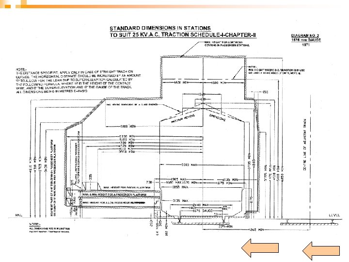
Schedule I chapter II (Station yard) Min. dist. Centre to centre of track : (i) For existing works 4265 mm (ii) For new works / Alt. 5300 mm Max. gradient in Station yard : (i) For existing works 1 in 400 (ii) For new works / Alt. 1 in 1200 Note: There must be no change of grades within 30 meters of any points & crossings.

The power of condonation for gradient steeper than 1 in 1200 in case of new work (As per Corrigendum to C. S. No. 12) Gradient Authority Steeper than 1 in 1200 and Personal approval of G. M. up to 1 in 400 through COM of the zonal Railway after making efforts for providing grade as flatter as possible Steeper than 1 in 400 and up to 1 in 260 C. R. S. Steeper than 1 in 260 Railway Board through C. C. R. S.

Chapter ii contd. … Horizontal dist. From C/L of track to Face of platform coping Face of goods platform coping Face of any platform wall Max. 1680 mm Min. 1670 mm 1680 mm 1670 mm 1905 mm 1675 mm New platform wall should be built to maximum dimensions and the coping corbelled out to 1675 mm.

Platform on curved track No passenger platform in case of new line, would be constructed on a curve having radius less than 875 M n Extra allowance to be reduced by 51 mm for platform, inside of curve. n Extra allowance to be reduced by 25 mm for platform, outside of curve. n

Chapter ii contd. … Height above rail level – For high level passenger platform For medium level passenger platform For goods platform Max. 840 mm Min. 760 mm 455 mm - 1065 mm -

Railway Board’s directives for Mumbai suburban section Vide letter No. 2007/CEDO/SD/O dated 19. 02. 14, Railway Board has conveyed Board’s approval to change the height range of platform in Mumbai suburban section from 760 -840 mm to 840 -920 mm. n RDSO has been asked to submit draft correction slip for Board’s approval which is yet to be issued. n
 Minimum Horizontal distance of any building on")
Chapter II Contd. n (Buildings and structures) Minimum Horizontal distance of any building on a passenger platform from center of track. Height of the structure Distance From P/F level to 305 mm above P/F level 5180 mm 5330 mm From 305 mm above P/F level to 3430 mm above RL 5330 mm From 3430 to 4115 mm above RL for existing work and 5330 mm 3810 mm From 3430 to 4610 mm above RL for new work
 n Min. horizontal distance of any bldg. or")
Contd. …. . (CS No. 11) n Min. horizontal distance of any bldg. or longitudinal boundary fence from centre line of track of passenger platform which is not an island (For New works) ¨ Minimum 6830 mm ¨ Recommended 12130 mm Note: Recommended dimension is for setting back the platform to make room for an additional track in future, without infringing minimum distance.

Chapter No. 2 contd. …. n Minimum horizontal distance from center line of track to a pillar, column, lamp of similar isolated structure on a passenger platform. Height Distance From platform level to 4570 mm increasing 305 mm above platform level uniformly to 4720 mm From 305 mm above platform 4720 mm level to 3705 mm above rail level

CHAPTER II CONTD… POINTS & CROSSINGS : - Clearance of Max. Min. 48 mm 44 mm Check rail opposite nose of crossing --------Do--------- 45 mm 41 mm (In case of PRC T/O ) Wing rail at nose of crossing ---------Do-------(In case of PRC T/O ) 48 mm 44 mm 45 mm 41 mm

Chapter ii contd. … Points & Crossings : Clearance bet. Toe of open switch and stock rail. (i) For Existing work 95 mm (ii) For new work or alteration to existing work 115 mm Minimum Radius of curvature for Slip points, Turn outs, Cross over. 218 m
 1")
Chapter ii contd. … Points & Crossings : Minimum angle of crossing. (ordinary) 1 in 16 Crossing as flat as 1 in 20 will usually be sanctioned if recommended by CRS. Minimum length of Tongue Rail. 3660 mm Diamond crossing not to be flatter than 1 in 8 1/2 Diamond crossing as flat as 1 in 10 will usually be sanctioned if recommended by CRS.
 Condition Length of siding")
Length of siding for New work (C. S. No. 8) Condition Length of siding Where the ruling gradient is 750 Meters 1 in 100 and flatter Steeper than 1 in 100 Length of longest train permitted in the section + 35 M Clear available length denotes : 1. Distance between foot of signal and FM in rear on the same line in case of main line and Directional loop at station yard 2. In case of common loop, distance between two starter signals of opposite direction on the same line.

Maximum Moving Dimensions Description 3250 mm wide stock 3135 mm 3660 mm Wide stock 3505 mm Max. width over all projections from 305 mm to 1082/1145 mm above RL when fully loaded 3250 mm 3660 mm 3135 mm 3505 mm Max. width with over open doors, including all projections for goods vehicle 4265 mm 4725 mm Max. height above RL for a width of 760 mm on either side of the centre of unloaded vehicle 4265 mm 4725 mm Max. width over all projections, at 305 mm above RL, when fully loaded
 n Wheel Gauge 1599 mm-1602 mm. n Tread Dia")
SCHEDULE I CHAPTER IV (A) n Wheel Gauge 1599 mm-1602 mm. n Tread Dia of new wheel 914 mm-1092 mm. n Flange Projection 28. 5 mm-35. 0 mm n Flange Thickness 16 mm- 29. 4 mm* * As per CS No. 14

Contd. … Tyre width Floor height above RL n Passenger n Goods n 127 mm minimum. 1345 mm-1220 mm. 1345 mm-1145 mm. n Buffer height above RL 1030 mm-1105 mm n Maxim Wheel Base for 4 -Wheeler - 6100 mm
 CONTD… Min. Wheel base for bogie truck Min. Wheel base for")
SCHEDULE I CHAPTERIV(A) CONTD… Min. Wheel base for bogie truck Min. Wheel base for pass. Bogie 1830 mm. 2440 mm. Min. Dist. Bet bogie centres 2/3 vehicle length Max. Dist bet. Bogie centres: 14. 900 m. * * CS No. 14 Max. Lenth of body or roof: 4 -Wheeler (3200 mm wide ) Bogie vehicles (3250 mm. Wide) 8540 mm. 21340 mm
 A. C. MIN. HT. OF UNDERSIDE OF LIVE WIRE: BRIDGES &")
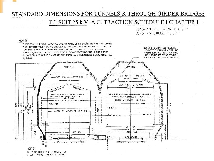
SCHEDULE V (A) A. C. MIN. HT. OF UNDERSIDE OF LIVE WIRE: BRIDGES & TUNNELS 4800 mm IN OPEN 5500 mm SHEDS 5800 mm LEVEL CROSSINGS 5500 mm n MAX. VARIATION OF LIVE WIRE EITHER SIDE : STRAGIHT 200 mm CURVES 300 mm n MAX. WITDTH OF PENTOGRAPH 1800 mm n
for 3250 mm wide stock 3660")
SCHEDULE-II Min. dist C/L to C/L of track i)for 3250 mm wide stock 3660 mm ii) for 3660 mm wide stock 4040 mm n Min. clear dist. From C/L of Track to any fixed structure From RL to 1065 mm above Rail level 1675/1905 mm n

Contd. … From 1065 mm to 3505 mm above R/L 1980/2135 mm n 4265 mm above R/L 2055 mm ( with SR 16 kmph ) 1980 mm n Min. clear height above R/L for a dist. of 305 mm/915 mm on either of centre of track 4420 mm / 5030 mm n

Over-dimensioned consignment n When a consignment whose length, width and height are such that one or more of them infringe the standard moving dimension at any point during the run from start to destination, then the consignment is called O. D. C.
 Which exceed the maximum")
Class ‘A’ O. D. C. (Permitted out of gauge loads) Which exceed the maximum moving dimensions but do not infringe any fixed structure on the route by a net clearance of 150 mm and above and gross clearance 225 mm and above.
 – Net")
Contd. … Class ‘B’ O. D. C. (Exceptional out of gauge load) – Net clearance not less than 75 mm but less than 150 mm, gross clearance 150 mm to 225 mm. Class ‘C’ O. D. C. -(Extraordinary out of gauge loads) Net clearance are less than 75 mm and gross clearance less than 150 mm

Speed Restrictions for ‘A’ Class O. D. C. Gauge Speed Restriction B. G Escort Sanctionin g authority Sectional speed of Not COPS four wheeler required 30 kmph where gross clearances is less than 380 mm. Movement by day/night

Speed Restrictions for ‘B’ Class O. D. C. Gauge Speed Restriction B. G. Escort Sanctionin g authority 40 kmph by day and SSE CE night During night stop (C&W) dead and proceed T. I. slowly at approach of structure having gross clearance less than 225 mm.

Speed Restrictions for ‘C’ Class O. D. C. Gauge B. G. Speed Restriction 25 kmph Movement by day only Escort Sanctioning authority SSE/SE (C&W) T. I. SSE/SE (P. Way) TRD staff CRS

THANKS
- Slides: 67