Pimpri Chinchwad polytechnics COURSE MEASUREMENT AND CONTROL 17528
 Sub. Teacher-Ms. Nilesha Patil")


")


 It is the closeness with the true value of the")


 Operational error B) personal error.")


 Errors: � International agreement has been reached on ambient condition")


 Noise: It is defined as any signal that does not")


Length")
 Sliding contact devices: In the sliding contact type of variable resistance")


 High frequency response: They offer very high frequency")


- Slides: 85
Pimpri Chinchwad polytechnics COURSE: MEASUREMENT AND CONTROL (17528) Sub. Teacher-Ms. Nilesha Patil
CO: Know concept of measurement , errors in measurement, static and dynamic characteristics and Transducers. Chapter-01 INTRODUCTION AND OF MEASUREMENT SIGNIFICANCE
Measurement is actually the process of estimating the values that is the physical quantities like; time, temperature, weight, length etc. Each measurement value is represented in the form of some standard units. The estimated values by these measurements are actually compared against the standard quantities that are of same type.
Significance of Measurements � We require measuring quantities for performance in our day to day activities. � Fundamental requirement of any process is the measurement. � i. e. input is fed to the system it undergoes a process output is indicated. � i. e. output is compared with input-measurement � Measurement provides the fundamental basis for research & development as it involves measurement of various quantities and parameters. � Measurement is also considered as a method of inspection
Significance of Measurements � Establish the cost of products on the basis of amount of material, power, time & labor, etc. � Place/give realistic tolerance for each of the measured values.
Application of Measurements � 1. Design of manufactured goods � 2. Design of machinery to perform manufacturing operations � 3. Design of power sources � 4. Design of roads, waterways and other system. � 5. To study the operation features, limitation and difficulties that are inherent in the systems. � 6. For proper maintenance of the equipment. � 7. To determine the system response(Reply of the systems to given input) � 8. For correct recording of the output data(weather forecasting, experimental values, interpretation etc. )
Fundamental methods of Measurement Two basic methods are commonly employed for measurement. � (a) Direct comparison with primary or secondary standard. � (b) Indirect comparison through the use of calibrated system. Direct comparison � In this method, measurement is made directly by comparing the unknown magnitude with a standard & the result is expressed by a number. � The simplest example for this would be, length measurement using a meter scale.
Fundamental methods of Measurement Direct comparison methods are quite common for measurement of physical quantities like length, mass, etc. � It is easy and quick. � Drawbacks of Direct comparison methods � The main drawback of this method is, the method is not always accurate and reliable. � Also, human senses are not equipped to make direct comparison of all quantities with equal facility all the times. � Also, measurement by direct methods are not always possible, feasible and practicable. �
Indirect comparison Most of the measurement systems use indirect method of measurement. � In this method a chain of devices which is together called as measuring system is employed. � The chain of devices transform the sensed signal into a more convenient form & indicate this transformed signal either on an indicator or a recorder or fed to a controller. � i. e. it makes use of a transducing device/element which convert the basic form of input into an analogous form, which it then processes and presents as a known function of input. � For example, to measure strain in a machine member, a component senses the strain, another component transforms the sensed signal into an electrical quantity which is then processed suitably before being fed to a meter or recorder. �
Measurement system �A general template for a measurement system is illustrated in fig. � Basically such a system consists of part or all of four general stages: � (1) Sensor-transducer stage � (2) Signal -conditioning stage � (3) Output stage � (4) Feedback -control stage
Measurement system sensor – stage transduc er stage Signal conditioni ng stage control stage Output stage
Measurement system � The sensor is a physical element that employs some natural phenomenon by which it senses the variable being measured. �. The transducer converts this sensed information into a detectable signal, which might be electrical, mechanical, optical, or otherwise. � Signal conditioning equipment takes the transducer signal and modifies it to a desired magnitude. � output stage indicates or records the value measured. � control stage, contains a controller that interprets the measured signal and makes a decision regarding the control of the process.
Types of instrument of measurement: - The instrument can be classified into three types � Primary Instrument: ◦ Direct Comparison with reference standard. ◦ For example the length measurement by ruler Secondary Instrument: indirect comparison by converting it into some other form. ◦ For example temperature measurement by mercury in glass thermometer � Tertiary Instrument: � two conversion of parameter are involved. � For example measuring of shaft speed by electrical tachometer � Mode
Nature of Contact � -The instruments can be classified into two types ◦ Contact type: ◦ when initial sensing element comes in direct contact with the medium whose parameter are to be measured. ◦ Temperature measurement by thermometer ◦ Non Contact type: ◦ when the initial sensing element does not comes in contact with the medium whose parameter are to be measured. ◦ Temperature Measurement by radiation pyrometer.
Condition of Pointer: � The Classification is as � a. Null Type: � The pointer is maintained at a fixed position and measurement is done by balancing � b. Deflection type: � The pointer is deflected with respect to origin to get the measured quantity
Power Source Required � : -The classification is as follows: � a. Self sufficient Instrument (Active ): � do not need external power � Thermometer � b. Power operated instrument (Passive): need external source of power � Tachometer
Nature of output signal � Analog instrument � It is a continuous and step less function. � Voltmeter, wrist watch, fuel gauge. � Digital instrument � It is in the form of discrete pulse or steps utilizing a coding system and involves a counting process. � Digital temperature indicator, digital weight mater, odometer.
• RANGE • SPAN • RELIABILITY • CALIBRATION • DRIFT • REPEATABILITY • REPRODUCIBILITY
Range and spam.
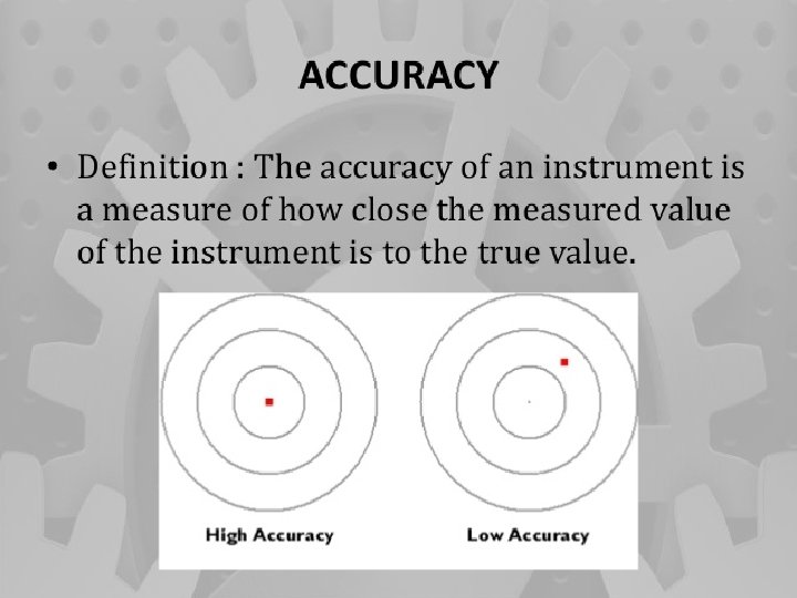
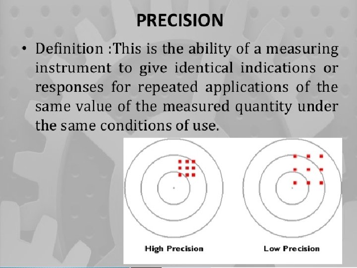
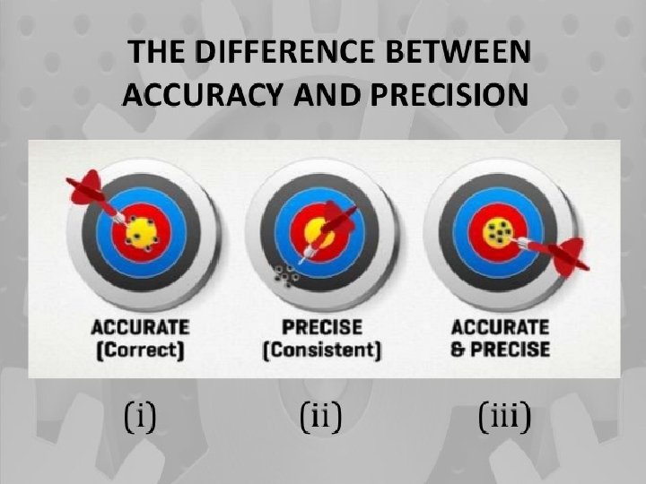
Accuracy and Precision 1) It is the closeness with the true value of the quantity being measured. It is a measure of reproducibility of the measurements 2) Accuracy can be improved Precision cannot be improved 3) Accuracy depends upon simple techniques of analysis Precision depends upon many factors and requires many sophisticated techniques of analysis 4) Accuracy is necessary but not sufficient condition for precision Precision is necessary but not a sufficient condition for accuracy
Reliability � It is defined as the possibility that can an instrument will perform its assigned function for given specific period of time under given conditions. � The reliability of a device is affected not only the choice of parts in it but also manufacturing methods, quality of maintenance and the type of user.
Standards � Primary, Secondary, Tertiary & Working Standards: � Primary standard: It is only one material standard and is preserved under the most careful conditions and is used only for comparison with Secondary standard. � Secondary standard: It is similar to Primary standard as nearly as possible and is distributed to a number of places for safe custody and is used for occasional comparison with Tertiary standards.
Standards � Tertiary standard: It is used for reference purposes in laboratories and workshops and is used for comparison with working standard. � Working standard: It is used daily in laboratories and workshops. Low grades of materials may be used.
calibration � Calibration is the process of establishing the reliability of a measuring instrument. � This involves the comparison of the instruments to be calibrated with, either a primary standard, secondary standard or a known input source.
Methods of calibration � Primary calibration � When a measuring system is calibrated using primary standards, it is called primary calibration. � E. g. standard resistor , standard cell etc. � Secondary calibration � When a system that has been calibrated using primary standards is used to calibrate another device, then it is called secondary calibration. � E. g. general purpose lab and industries.
Methods of calibration � Direct calibration is the process of calibrating a system with a known input source.
Repeatability � Repeatability describes the closeness of output reading when the same input is applied repetitively over a short period of time with same measurement condition. � Same instrument and observer, same location and same conditions of use maintained throughout. � It is ability of measuring instrument to give same value every time the measurement of given quantity is repeated.
Reproducability � Reproducability describes the closeness of out put readings for the same input when there are changes in method of measurement, observer, measuring instrument, location, condition of use and time of measurement.
Drift � It is an undesired gradual departure of the instrument output over a period of time that is unrelated to change in inputs operating conditions or load. 0 r � Drift: - The gradual shift in the indication or record of the instrument over an extended period of time, during which the true value of the variable does not change is referred to as drift.
47 Output sensitivity drift zero drift input Output input sensitivity drift zero drift input
Zero Drift: - if the whole calibration is shifted by the same amount due to slippage or due to undue warming up of tube of electronic tube circuits, zero drift sets in. zero setting can prevent this. Span Drift or Sensitivity Drift: - If there is proportional change in the indication all along upward scale, the drift is called span drift or sensitivity drift. Hence higher calibrations get shifted more than lower calibrations.
Dynamic terms and characteristics � Speed of response � In measuring instruments the speed of response is defined as the value of the rapidity with which an instrument responds to a change in the value of quantity being measured.
Fidelity � Fidelity is the ability of the measuring instrument to reproduce the output in the same form as the input. � E. g. if the input provided is sine wave then output should be sine wave.
Dynamic error � The difference between the indicated quantity and the true value of the time varying quantity is the dynamic error, here static error of an instrument is assumed to be zero.
overshoot � Because of mass and inertia a moving part i. e. the pointer of the instrument does not immediately come to rest in the final deflected position. � The pointer goes beyond the steady state i. e. overshoot. � The overshoot is defined as the maximum amount by which the pointer moves beyond the steady state.
Errors � Difference between true value of the size being measured and the value found by measurement. � Classification of errors � Single transmission errors � environmental error � Observation error � Operational errors
Classification of error Gross error or Human error A) Operational error B) personal error. 2) Systematic error A) Instrumental error B)environmental error. 3)Random error. 1)
Operational error �A different type of flow meter will read inaccurately if it is placed immediately after valve or a bend. � A thermometer not read properly if its sensitive portion is not properly installed. � A pressure gauge will correctly indicate pressure only when it is exposed only to the pressure which is to be measured.
Personal error � This type of error mainly covers human mistake in reading instruments and recording and calculating measurement results. � For e. g. he may read as 31. 5 c instead of 21. 5 c due to oversight. � He may change reading while recording. � Cause of this error may be � 1)Individual limitation of human being. � 2)Lack of experience. � 3)Observational error.
Observational errors � As the name suggests these types of errors are due wrong observations. � parallax: due to the line of vision is not normal to the scale. � Unit conversion: inaccurate conversion of units � Personal bias: a tendency to read high or low readings. � Wrong scale reading and wrong recording data.
Instrumental error � These errors are inherent in instrument because of their mechanical structure. � They may be due to construction , calibration or operation of measuring instrument. � E. g. if the spring of a permanent magnet instrument has become weak, the instrument will always read high. � To minimize such type of error instrument may be recalibrated.
Translation and signal transmission error � Instrumental error may arise due to error in translation and transmission of signal. � The instrument may not sense or translate the measured effect with complete fidelity. � The error are remedied by calibration and by monitoring the signal at one or more point along transmission path.
Environmental (Ambient /Atmospheric Condition) Errors: � International agreement has been reached on ambient condition which is at 200 C temperature, 760 mm of Hg pressure and 10 mm of Hg humidity. � Instruments are calibrated at these conditions. If there is any variation in the ambient condition, errors may creep into final results. Of the three, temperature effect is most considerable.
Environmental errors � This type of error arises due to conditions external to instrument. � External condition includes temperature, pressure, humidity or it may include external magnetic field. � Following are the steps that one must follow in order to minimize the environmental errors: � (A)Try to maintain the temperature and humidity of the laboratory constant by making some arrangements. � (B)Ensure that there should not be any external magnetic or electrostatic field around the instrument.
Random error/residue error � The disturbance about which we are unaware lumped together and called random or residual, error caused by these causes are called random or residual errors. � Reading shown by a hand tachometer would vary with the pressure with which it is pressed against the shaft. � In well designed experiments, few random errors usually occur but they become important In high accuracy work. � Some of the reasons of the appearance of these errors are known but still some reasons are unknown. � Hence we cannot fully eliminate these kinds of error.
Sources of errors (1) Noise: It is defined as any signal that does not convey useful information. � (2) Design limitations: These are certain inevitable factors such as friction & resolving power which lead to uncertainty in measurements. � (3) Response time: It is the time lag between the application of input signal & output measurement � (4) Environmental effects: The change in atmospheric temperature may alter the elastic constant of a spring, the dimensions of a linkage, electrical resistance etc. similarly other factors such as humidity, pressure etc. also affect measurements. � (5) Errors in observation & Interpretation: It is the mistake of operators in observing, interpreting & recording the data. � (6) Poor maintenance of the system �
Transducer It detects and transforms the sensed signal into a more useful form. � Classification of transducer � 1) Mechanical � A) elastic member e. g. springs and bourdon tube. � B) Thermal e. g. thermometer. � C) Hydro-pneumatic transducer e. g. venturi, orifice plate. � 2) Electrical � A)passive B) Active a) resistance a) thermocouple b) capacitive b) photo voltaic c) inductive c) piezoelectric pick d) voltage �
Active & Passive Transducers � Active transducers � Also known as self generating type transducers Develop their own voltage or current. � Energy required for production of output signal is obtained by quantity being measured. � Ex, Electronic & Piezo electric transducers. � Passive Transducers: � Also known as externally powered transducer � Derive the power for energy conversion from an external power source � Ex: Bonded electrical resistance strain gauges
Resistive transducer � Resistive transducer are those in which the resistance changes due to change in some physical phenomenon. � The resistance of an electrical conductor is given by, � R=ρL/A � R=resistance in ohm. � L=length of the conductor in cm � A=cross sectional area of the conductor in cm 2 � ρ= resistivity of material in ohm-cm.
Resistive transducer � The electrical resistance thus can be varied by varying � 1)Length 2) cross-sectional area 3) resistivity Or a combination of these. � Any phenomenon or a physical variable which can vary any one of the above parameters can be transduced as change of resistance. � E. g. resistivity changes with temperature used for temperature measurement by device Thermistors, RTD etc.
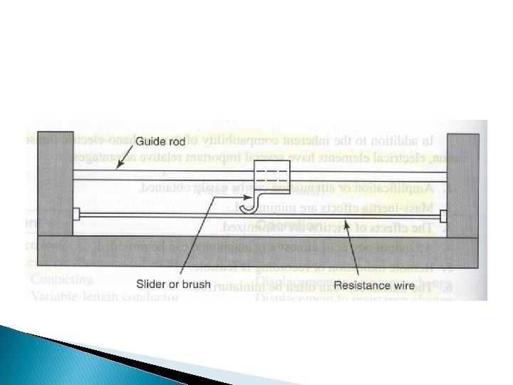
example � 1) Sliding contact devices: In the sliding contact type of variable resistance transducers there is a long conductor whose effective length is variable. � One end of the conductor is fixed, while the position of the other end is decided by the slider or the brush that can move along the whole length of the conductor. � The slider is connected to the body whose displacement is to be measured. � When the body moves the slider also moves along the conductor so its effective length changes, due to which it resistance also changes.
example � The effective resistance is measured as the resistance between the fixed position of the conductor and the position of the sliding contact. � The value of the resistance is calibrated against the input quantity, whose value can be measured directly. � One of most popular sliding contact type of variable resistance transducer is the potentiometer. � These devices can be used to measured linear as well as angular displacement.
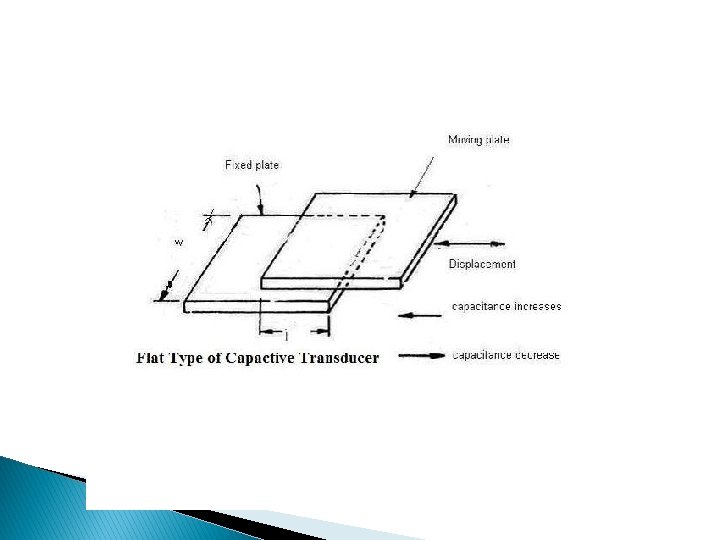
Capacitive Transducer � Capacitance is the ability of a body to store an electrical charge. � The capacitive transducer or sensor is nothing but the capacitor with variable capacitance. � The capacitive transducer comprises of two parallel metal plates that are separated by the material such as air, which is called as the dielectric material.
Capacitive Transducer � In the typical capacitor the distance between the two plates is fixed, but in variable capacitance transducers the distance between the two plates is variable. � In the instruments using capacitance transducers the value of the capacitance changes due to change in the value of the input quantity that is to be measured. � This change in capacitance can be measured easily and it is calibrated against the input quantity, thus the value if the input quantity can be measured directly.
Capacitive Transducer � The capacitance C between the two plates of capacitive transducers is given by: � C = εo x εr x A/ D � Where C is the capacitance of the capacitor or the variable capacitance transducer � εo is the absolute permittivity � εr is the relative permittivity � The product of εo & εr is also called as the dielectric constant of the capacitive transducer. � A is the area of the plates � D is the distance between the plates
Capacitive Transducer � It is clear from the above formula that capacitance of the capacitive transducer depends on the area of the plates and the distance between the plates. � The capacitance of the capacitive transducer also changes with the dielectric constant of the dielectric material used in it.
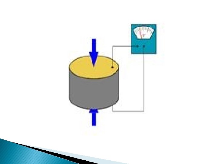
piezoelectric transducers There are certain materials that generate electric potential or voltage when mechanical strain is applied to them or conversely when the voltage is applied to them, they tend to change the dimensions along certain plane. This effect is called as the piezoelectric effect. � The piezoelectric transducers work on the principle of piezoelectric effect. � When mechanical stress or forces are applied to some materials along certain planes, they produce electric voltage. � This electric voltage can be measured easily by the voltage measuring instruments, which can be used to measure the stress or force. �
piezoelectric transducers � The voltage output obtained from the materials due to piezoelectric effect is very small and it has high impedance. � To measure the output some amplifiers, auxiliary circuit and the connecting cables are required. � Some of the materials that exhibit piezoelectric effect are quartz, Rochelle salt, polarized barium titanate, ammonium dihydrogen, ordinary sugar etc.
advantages as mentioned below: � 1) High frequency response: They offer very high frequency response that means the parameter changing at very high speeds can be sensed easily. � 2) High transient response: The piezoelectric transducers can detect the events of microseconds and also give the linear output. � 3) The piezoelectric transducers are small in size and have rugged construction. � Limitations of Piezoelectric Transducers � Some of the limitations of piezoelectric transducers are: � 1) Output is low: The output obtained from the piezoelectric transducers is low, so external electronic circuit has to be connected. � 3) Forming into shape: It is very difficult to give the desired shape to the crystals with sufficient strength. �
Inductive Transducers � The inductive transducers work on the principle of the magnetic induction of magnetic material. � The process by which a substance, such as iron or steel, becomes magnetized by a magnetic field. � Just as the resistance of the electric conductor depends on number of factors, the induction of the magnetic material depends on a number of variables like the number of turns of the coil on the material, the size of the magnetic material, and the permeability (is the measure of the ability of a material to support the formation of a magnetic field within itself) of the flux path(The direction and flow of the magnetic forces of attraction created by a magnet)
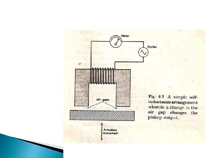
� In the inductive transducers the magnetic materials are used in the flux path and there are one or more air gaps. � The change in the air gap also results in change in the inductance of the circuit and in most of the inductive transducers it is used for the working of the instrument.
� The figure 1 below shows the single coil inductive circuit. � Here the magnetic material is connected to the electric circuit and it is excited by the alternating current. � At the bottom there is another magnetic material that acts as the armature. � As the armature is moved, the air gap between the two magnetic material changes and the permeance of the flux generated by the circuit changes that changes the inductance of the circuit and its output. � The output meter directly gives the valve of the input mechanical quantity.
THANK YOU