Pimpri Chinchwad polytechnics COURSE MEASUREMENT AND CONTROL 17528
 Sub. Teacher : Ms. Nilesha U.")


 2) 3) 4) 5) Simple in construction Linear output High sensitivity")
 It is used in automobile for a inspection purpose of wheel.")


![CONSTRUCTION �It consists of three distinct parts : 1. The filament [Cathode] 2. The](https://slidetodoc.com/presentation_image_h2/a8604e9bdc3d46f4ffd19c0deef83748/image-53.jpg "CONSTRUCTION �It consists of three distinct parts : 1. The filament [Cathode] 2. The")


- Slides: 61
Pimpri Chinchwad polytechnics COURSE: MEASUREMENT AND CONTROL (17528) Sub. Teacher : Ms. Nilesha U. Patil
Chapter No. -02 Displacement & Pressure Measurement CO- Explain the working of various displacement and pressure measuring transducers.
Displacement Measurement �LVDT �RVDT �POTENTIOMETER
LVDT � LVDT are a Linear Variable Differential Transformer. � LVDT can convert the rectilinear motion of object to which it is coupled mechanically into a corresponding electric signal. � It can be measure up to the +/-0. 5
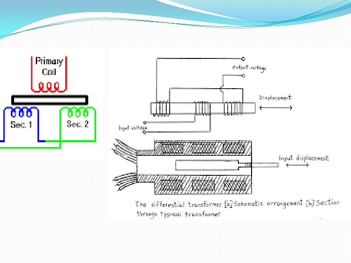
PRINCIPLE � The principle is based on the modulation of the excitation signal. � The motion of magnetic core changes the mutual inductance of two secondary coils relative to primary coils. � It is based on a variable-inductance principle for displacement measurement. � In which, the output an ac. Voltage is proportional to the core displacement.
CONSTRUCTION � There are three coils are connected as shown in fig. � A device has one primary coil & two secondary windings with magnetic core free to move inside the core. � Core is attached to the moving part on which displacement is to be measured. � Secondary winding are alternatively placed.
WORKING � When ac. Input is given to the primary coil, an ac. Output voltage depending on the magnetic coupling , between the core an the coils. � Output depends on the position of the core. � Basically , linear range is specified for a differential transformer , and when core is operated within the range, it is called as LINEAR VARIABLE DISPLACEMENT TRANSFORMER. � When emf is induced in secondary coil will be same as the resulting input , is zero , therefore it is called as null position. � The difference of two voltages across the output terminals of LVDT gives the measure of physical position of the central core.
LVDT SPECIFICATION � Stroke or core displacement – 0. 1 mm to 100 mm. � Input frequency – 20 to 50 KHz. � Sensitivity – 0. 5 to 30 MV/V input / 0. 05 mm � Power consumption --< 1 watt � Output impendence -- <50 � Resolution -2*10^-3 mm � Input or excitation voltage – 3 to 15 V
ADVANTAGES � Simple in construction. � Easy to handle. � Good accuracy. � Instrument is inexpensive. � Low power consumption. � Good sensitivity.
DISADVANTAGES � It is designed for a specific input frequency. � The device become complicated , when null position is required. � Required external power supply. � Vibration in core is affected by performance.
APPLICATION � Displacement measurement. � Pressure measurement. � In CNC machine. � In creep testing machine. � Force measurement.
Ø What is the meaning of RVDT ? q RVDT stands for Rotary Variable Differential Transducer. q Basically a transducer means a device which converts one form of energy (or signal ) into another form. q As the name suggest that, it is used for angular displacement measurement. And also it converts the rotary motion (i. e. mechanical energy) into e. m. f. (i. e. electrical energy) as a output.
Construction : - Fig. shows the constructional details of RVDT. It consist of a primary winding which is connected across single phase A. C. supply. Magnetic core or armature is placed in air gap such that it will be freely able to move in either direction on angular displacement of shaft. Also the armature core has elliptical or cam shape and the mechanical linkage is connected to it.
Principle : It works on the principle of modulation of excitation. Working : Ø When single phase A. C. supply is switched on. It produces magnetic flux, which completes their path through secondary winding. Therefore, according to Faraday’s law of electro-magnetic induction e. m. f. will induce in the secondary winding. Ø When core is at central position , e. m. f. induced in secondary winding ES 1 & ES 2 will be equal and opposite , therefore output E 0=0. Ø When displacement of armature core takes place in either of direction i. e. clockwise or anti-clockwise, due to unequal flux distribution e. m. f. will be measured between two secondary terminals so that e. m. f. measure is directly calibrated in terms of quantity being measured. Ø The greater angular displacement, gives greater differential output. Therefore response of RVDT is linear.
Advantages : 1) 2) 3) 4) 5) Simple in construction Linear output High sensitivity Good accuracy It can be used to measure small angle of displacement i. e. +/- 5 Degree Disadvantages : 1) 2) 3) 4) External power source (Only A. C. ) require Vibrations may produce error. Practical limit of angular measurement is about +/-60 Degree. The performance is affected by temperature variation.
Applications : 1) It is used in automobile for a inspection purpose of wheel. 2) It is used in automats to locate various positions. 3) It is used in flight control, steering control of automobile. 4) It is widely used to locate position of load.
PRESSURE MEASUREMENT
CLASSIFICATION • LOW PRESSURE GAUGE 1. MCLEOD GAUGE 2. THERMAL CONDUCTIVITY GAUGE 3. IONIZATION GAUGE 4. THERMOCOUPLE VACCUM GAUGE 5. PIRANI GAUGE • HIGH PRESSURE GAUGE ELASTIC TYPE 1. DIAPHRAGM 2. BELLOWS 3. BOURDON TUBE ELECTRICAL TYPE 1. ELECTRICAL RESISTANCE TYPE 2. PHOTOELECTRIC PRESSURE TRANSDUCER 3. PIEZOELECTRIC TYPE 4. VARIABLE CAPACITOR TYPE
ELASTIC PRESSURE ELEMENTS �These types of gauges use elastic members for sensing pressure at primary stage so known as PRIMARY SENSING ELEMENT. �These elastic members convert the pressure into mechanical displacement which can be directly read on pointer or can be converted into electrical signal using secondary transducer.
WORKING PRINCIPLE • When elastic member like diaphragm, bellows, bourdon tube is subjected to applied unknown pressure, it tend to deflect or deform results into mechanical displacement. • This displacement is proportional to applied pressure and it can be measured either by mechanical or electrical means.
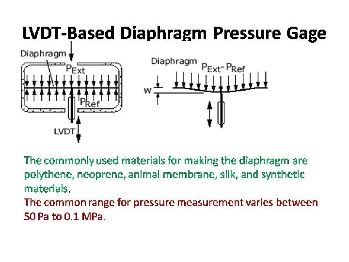
DIAPHRAGM • The diaphragm is a thin member of sheet metal made to precise dimension either in the shape of membrane or circular disc. • If unknown pressure is applied on one side of diaphragm it gets deflected. • The deflection of diaphragm is proportional to applied pressure. • The measure of the deflection is calibrated in terms of pressure.
SPECIFICATIONS OF DIAPHRAGM �For pressure range 0 to 6. 7 KPa membrane type diaphragm is used and for 0 to 350 KPa circular flexible disc type diaphragm is used. �Made up off phosphor bronze, beryllium copper, brass, teflon and monel.
TYPES �Flat type �Disc type �Corrugated type �Capsule
ADVANTAGE �They have moderate cost and simple in construction. �Good linearity. �Easy calibration with dead weight tester. �Connectivity to strain, capacitance and other electrical sensor. �They can measure gauge, absolute and differential pressure.
LIMITATIONS �Cannot avoid overloading. �Cannot tolerate vibrations and shocks. �Difficult to repair. �Range limited to relatively low to medium pressure.
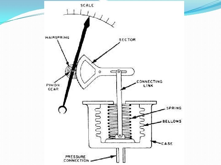
BELLOWS PRESSURE GAUGE • Bellows are pressure sensing elastic elements used for measurement of low and medium pressure. • When number of circular plates welded together in such a way that they can be expanded or contracted by the applications of pressure.
MATERIAL PROPERTY INCLUDES • • Easy to fabricate. High resistance to fatigue. Good ductility and strength. Less hysteresis effect.
WORKING • Pressure to be measured is applied from bottom which is fixed, expansion of bellows take place to upper side to which rod is connected. • The displacement of rod is directly proportional to the pressure inside the bellows. • This displacement is transferred to pointer moving over a calibrated scale.
ADVANTAGE �Simple and rugged construction. �Good for low to moderate pressure measurement. �Can used for measurement of gauge, absolute and differential pressures. �Relatively less expensive.
LIMITATION • Not suitable for very high pressure. • Friction and dirt may affect sensitivity. • For more accurate result, spring arrangement is necessary.
BOURDON TUBE PRESSURE GAUGES
PRESSURE: �FORCEACTING PER UNIT AREA IS KNOWN AS PRESSURE. �P=F/A �WHERE; �F= FORCE ACTING ON SURFACE �A= SURFACE AREA.
BOURDON TUBE
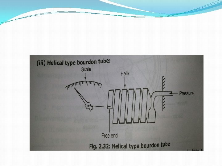
BOURDON TUBE IS MADE FROM FLATTENED TUBE BEND IN SUCH A WAY AS TO PRODUCE THE C, HELICAL OR SPIRAL SHAPE. ONE END OF TUBE IS SEALED AND OTHER END IS KEPT OPEN FOR FLUID TO ENTER WHOSE PRESSURE IS TO BE MEASURED. DUE TO THE APPLIED PRESSURE THE TUBE TENDS TO BE STRAIGHTEN OUT. THIS CAUSES THE MOVEMENT OF FREE END AND THIS DISPLACEMENT IS COMMUNICATED TO POINTER THROUGH SECTOR AND POINTER ARRANGEMENT. THE POINTER MOVES OVER SCALE, WHICH IS CALIBRATED TO READ PRESSURE.
MATERIAL THE BOURDON TUBE IS MADE UP OF DIFFERENT MATERIALS, LIKE BRASS, ALLOY STEEL, STAINLESS STEEL, BRONZE, COPPER ETC. GENERALLY PHOSPHOR BRONZE IS USED FOR LOW-PRESSURE APPLICATIONS. AND FOR HIGH PRESSURE STAINLESS STEEL IS USED.
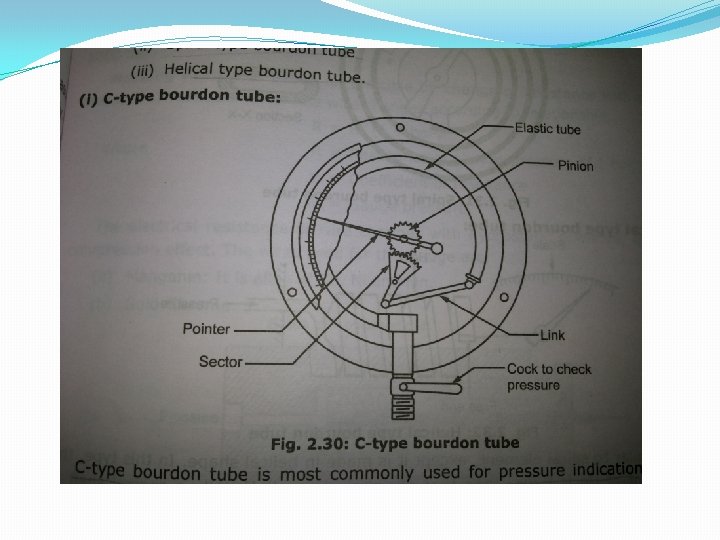
TYPES OF BOURDON TUBE v C-TYPE BOURDON TUBE v SPIRAL TYPE BOURDON TUBE v HELICAL TYPE BOURDON TUBE
‘C’ TYPE BOURDON TUBE IS MOST COMMONLY USED FOR PRESSURE INDICATION. IT HAS OVAL SHAPE ELASTIC TUBE. WORKING: - WHEN GAUGE IS CONNECTED TO THE POINT WHOSE PRESSURE IS TO BE MEASURED, THEN THE FLUID RUSHES IN THIS TUBE. AS THE PRESSURE IS INCREASED, BOURDON’S TUBE TENDS TO STRAIGHTEN DUE TO ELLIPTICAL SHAPE. THIS CAUSES THE FREE END OF THE TUBE TO MOVE. WITH THE HELP OF PINION AND SECTOR ARRANGEMENT, THE MOVEMENT OF END OF THE TUBE ROTATES THE POINTER MOVES OVER A CALIBRATED SCALE, WHICH DIRECTLY INDICATES THE PRESSURE.
ADVANTAGES OF BOURDON PRESSURE TUBE v. LOW COST. v. SIMPLE CONSTRUCTION. v. AVAILABLE IN WIDE VARIETY OF RANGE. v. HIGH ACCURACY AS COMPARED WITH COST.
DISADVANTAGES OF BOURDON PRESSURE TUBE v. LOW SPRING GRADIENT. v. SUSCEPTIBILITY TO SHOCK AND VIBRATION AND HYSTERISIS.
APPLICATIONS v. IT IS USED TO MEASURE THE PRASSURE IN BOILERS & CONDENSERS. v. IT IS ALSO USED IN HYDRAULIC SYSTEMS AND PNEUMATIC SYSTEMS ETC.
Macleod gauge
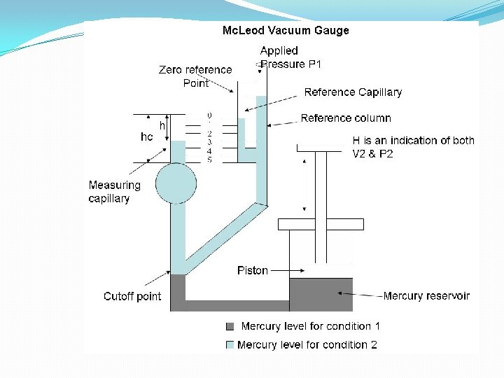
Basic Principle of Mc. Leod Vacuum Gauge: A known volume gas is compressed to a smaller volume whose final value provides an indication of the applied pressure. The gas used must obey Boyle’s law given by; P 1 V 1=P 2 V 2 Where, P 1 = Pressure of gas at initial condition (applied pressure). P 2 = Pressure of gas at final condition. V 1 = Volume of gas at initial Condition. V 2 = Volume of gas at final Condition. Initial Condition == Before Compression. Final Condition == After Compression. A known volume gas (with low pressure) is compressed to a smaller volume (with high pressure), and using the resulting volume and pressure, the initial pressure can be calculated. This is the principle behind the Mc. Leod gauge operation.
Description of Mc. Leod Vacuum Gauge: A reference column with reference capillary tube. The reference capillary tube has a point called zero reference point. This reference column is connected to a bulb and measuring capillary and the place of connection of the bulb with reference column is called as cut off point. (It is called the cut off point, since if the mercury level is raised above this point, it will cut off the entry of the applied pressure to the bulb and measuring capillary. Below the reference column and the bulb, there is a mercury reservoir operated by a piston.
Operation of Mc. Leod Vacuum gauge: The Mc. Leod gauge is operated as follows: The pressure to be measured (P 1) is applied to the top of the reference column of the Mc. Leod Gauge as shown in diagram. The mercury level in the gauge is raised by operating the piston to fill the volume as shown by the dark shade in the diagram. When this is the case (condition – 1), the applied pressure fills the bulb and the capillary. Now again the piston is operated so that the mercury level in the gauge increases. When the mercury level reaches the cutoff point, a known volume of gas (V 1) is trapped in the bulb and measuring capillary tube. The mercury level is further raised by operating the piston so the trapped gas in the bulb and measuring capillary tube are compressed. This is done until the mercury level reaches the “Zero reference Point” marked on the reference capillary (condition – 2). In this condition, the volume of the gas in the measuring capillary tube is read directly by a scale besides it. That is, the difference in height ‘H’ of the measuring capillary and the reference capillary becomes a measure of the volume (V 2) and pressure (P 2) of the trapped gas.
Applications The Mc. Leod Gauge is used to measure vacuum pressure. Advantages of the Mc. Leod Gauge: It is independent of the gas composition. It serves as a reference standard to calibrate other low pressure gauges. A linear relationship exists between the applied pressure and h There is no need to apply corrections to the Mc. Leod Gauge readings. Limitations of Mc. Leod Gauge: The gas whose pressure is to be measured should obey the Boyle’s law Moisture traps must be provided to avoid any considerable vapor into the gauge. It measure only on a sampling basis. It cannot give a continuous output.
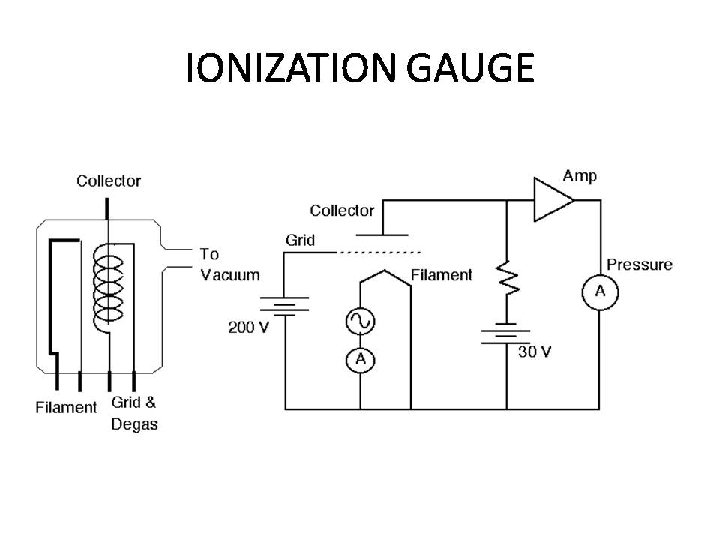
CONSTRUCTION �It consists of three distinct parts : 1. The filament [Cathode] 2. The grid & 3. The collector [Anode]
WORKING �Cathode emits the electrons. �Electrons travels towards grid. �IONIZATION occurs after collision of gas molecules with electrons. �Positive ion attracts towards anode forming current I 1 �Negative ion attracts towards cathode forming current I 2
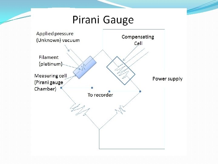
CONSTRUCTION �A Pirani Gauge chamber encloses a platinum filament. �A compensating cell to minimize variation caused due to ambient temperature change. �The Pirani Gauge chamber and the compensating cell is housed on a Wheatbridge circuit.
WORKING �. Pressure applied. �Constant current supply. �Filament heated. �Density changes. �Temperature changes. �Resistance changes. �Pressure detected
ADVANTAGES �Simple in design and easy to use. �Good response to pressure change. �Gives accurate results. �Readings can be taken from distances.
LIMITATIONS �It must be checked frequently. �It must be calibrated for different gases. �Needs electrical power.
THANK YOU……. .