Pimpri Chinchwad Polytechnic Nigdi Chapter 05 Flywheel Governors


 2) N 2 = (m + M) m x h =")


 N 2 = FM BM (m + M) m x 895")


 L 3")
- Slides: 52
Pimpri Chinchwad Polytechnic, Nigdi. Chapter 05 -Flywheel & Governors PRESENTED BY Ms. M. R. Zade
Course Name: Theory of Machines C 406 Year of Study: 2016 -17 C 406. 5 - Understand functions, operation and applications of flywheel, governor, brake, dynamometer, clutch and bearing.
STUDY OF FLYWHEEL
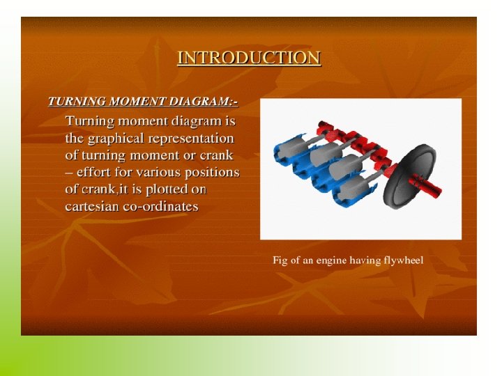
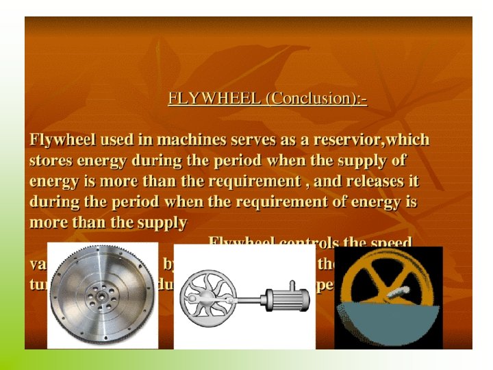
Flywheel definition • A flywheel is an inertial energy-storage device. It absorbs mechanical energy and serves as a reservoir, storing energy during the period when the supply of energy is more than the requirement and releases it during the period when the requirement of energy is more than the supply.
Flywheels-Function need and Operation • The main function of a fly wheel is to smoothen out variations in the speed of a shaft caused by torque fluctuations. If the source of the driving torque or load torque is fluctuating in nature, then a flywheel is usually called for. Many machines have load patterns that cause the torque time function to vary over the cycle. Internal combustion engines with one or two cylinders are a typical example. Piston compressors, punch presses, icengine steam engine.
Contdd… • Flywheel absorbs mechanical energy by increasing its angular velocity and delivers the stored energy by decreasing its velocity
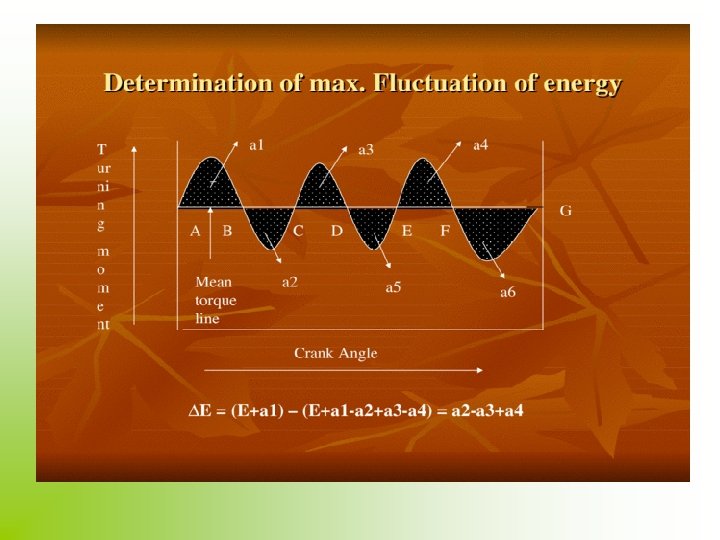
• Coefficient of Fluctuation of Speed- The difference between max. & min. speeds during a cycle is called maximum fluctuation of speed. The ratio of the max. fluctuation of speed to mean speed is called coefficient of fluctuation of speed. Let N 1 =Maximum speed in r. p. m. during the cycle,
STUDY OF GOVERNOR
INTRODUCTION The function of governor is to regulate the speed of an engine when there are variation in the load Eg. When the load on an engine increases, its speed decreases, therefore it is necessary to increase the supply of working fluid & vice-versa. Thus, Governor automatically controls the speed under varying load. Types of Governors: The governors may broadly be classified as 1)Centrifugal governors 2)Inertia governors
The centrifugal governors may further be classified as follows: Centrifugal governor Pendulum type Watt governor Loaded type Dead weight governor Porter governor Hartnell governor Hartung governor Spring controlled governor Proell governor Wilson - Hartnel governor Pickering governor
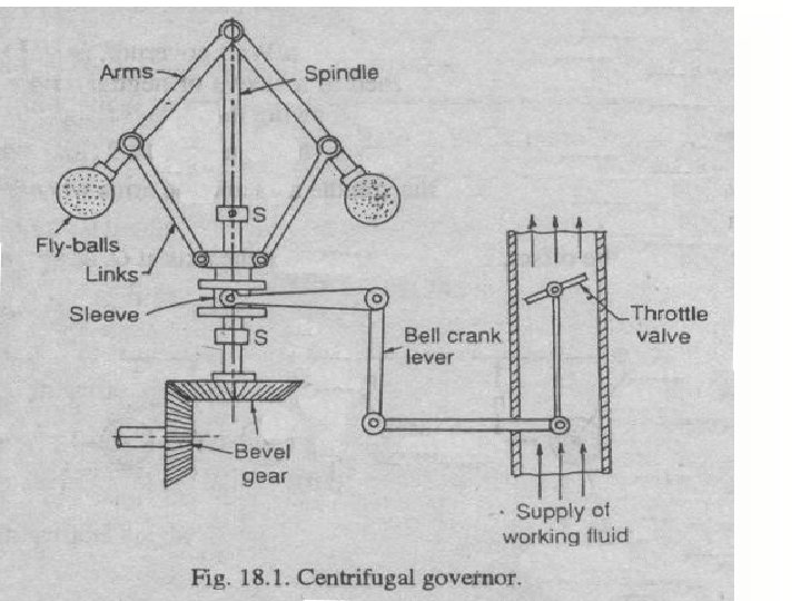
CENTRIFUGAL GOVERNORS The centrifugal governors are based on the balancing of centrifugal force on the rotating balls for an equal and opposite radial force, known as the controlling force. It consist of two balls of equal mass, which are attached to the arms as shown in fig. These balls are known as governor balls or fly balls.
when the load on the engine increases, the engine and the governor speed decreases. This results in the decrease of centrifugal force on the balls. Hence the ball moves inward & sleeve moves downwards. The downward movement of sleeve operates a throttle valve at the other end of the bell rank lever to increase the supply of working fluid and thus the speed of engine is increased. In this case the extra power output is provided to balance the increased load.
When the load on the engine decreases, the engine and governor speed increased, which results in the increase of centrifugal force on the balls. Thus the ball move outwards and sleeve rises upwards. This upward movement of sleeve reduces the supply of the working fluid and hence the speed is decreased. In this case power output is reduced.
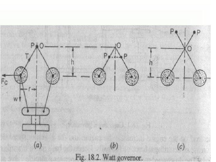
Watt Governor
It is the simplest form of centrifugal governor. It is basically a conical pendulum with links attached to a sleeve of negligible mass. The arms of governors may be connected to the spindle in following three ways; 1. The pivot P, may be on the spindle axis 2. The pivot P, may be offset from spindle axis & the arms when produced intersect at O. 3. The pivot P, may be offset, at the arms crosses the axis at O.
Let, m = Mass of the Ball in Kg w = Weight of the ball in Newton (= m. g) T = Tension in the arm in N = Angular velocity of arm and ball about the spindle axis in rad/sec. r = Radius of path of rotation of ball in mtrs. Fc = Centrifugal force acting on the balls in Newtons (m 2 r) h = Height of governor in mtrs.
Final Equations: Fc x h = W x r mr 2 x h = m. g. r h = g / 2 When g is in m/s 2 and is in rad/sec, then h is in mtrs. If N is the speed in r. p. m. then = 2 N / 60 H = 9. 81 / (2 N / 60) = 895 / N 2 mtrs.
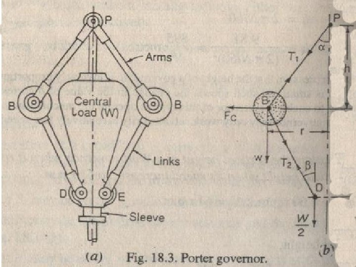
Porter governor
The porter governor is a modification of a Watt’s governor, with central load attached to the sleeve. The load moves up and down the central spindle. This additional downward force increases the speed of revolution required to enable predetermined level. the balls to rise to any
Let, m = mass of each ball T 1 = Force on the arm w = Wt. of each ball T 2 = Force in the links M = mass of central load W = Wt. of central load r = Radius o rotation h = Height of governor N = Speed o ball in r. p. m. = Angular speed o balls Fc = centrifugal force = Angle of inclination of arm to vertical = Angle of inclination of link to vertical
Final Equations: 1) 2) N 2 = (m + M) m x h = Without Friction h mg + ( M. g ± F)/2 m. g 3) 895 (m + M) m x (1+q) x 895 h x g 2 With Friction
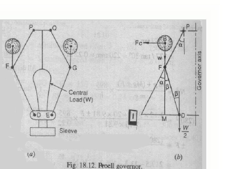
Proell Governor
The Proell governor has the balls fixed at B & C to the extension of the links DF & EG, as shown. The arms FP & GQ are pivoted at p & Q respectively. Consider the equilibrium of the forces on one half of the governor. The instantaneous centre (I) lies on the intersection of the line PF produced and the line from the D drawn perpendicular to the spindle axis. The perpendicular BM is drawn on ID
Final Equations: 1) N 2 = FM BM (m + M) m x 895 h Since h is in mtrs.
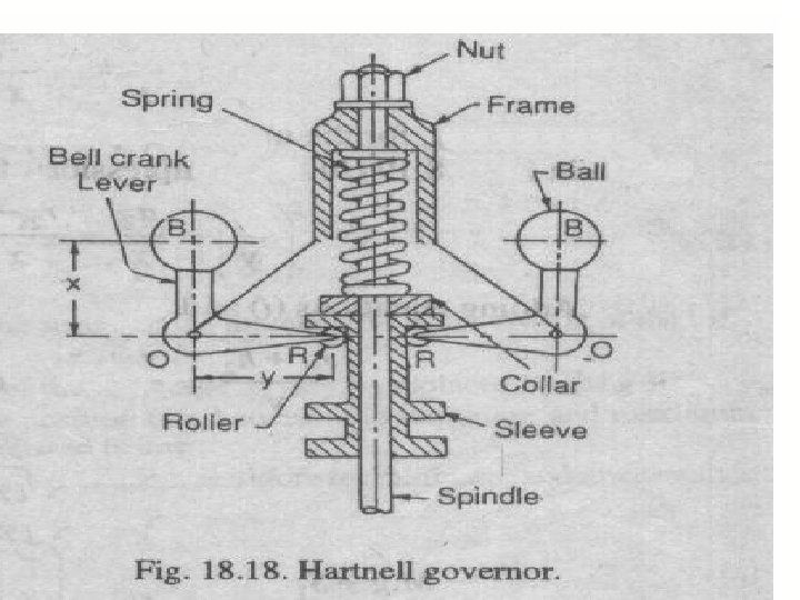
Hartnell Governor
It is a spring loaded governor, consists of two bell crank levers pivoted at the pts. O, O to the frame. Frame is attached to the governor spindle and therefore rotates with it. Each lever carries a ball at the end of the vertical arm OB & a roller at the end of horizontal arm OR. A helical spring in compression provides equal downward forces on two rollers through collar on the sleeve. The spring force may be adjusted by screwing a nut up or down on the sleeve.
Let, m = mass of each ball Fc 1 = centrifugal force at 1 M = Mass of sleeve in kg. Fc 2 = centrifugal force at 2 r 1 = Minimum radius of rotation r 2 = maximum radius of rotation S = Stiffness of the spring X = Length of vertical or ball arm Y = length of horizontal or sleeve r = Distance of fulcrum O from gov. axis. arm 1 = Angular speed of governor at r 1 2 = Angular speed of governor at r 2 S 1 = Spring force exerted on the sleeve at 1 S 2 = Spring force exerted on the sleeve at 2
Final Equations: S = Fc S 2 – S 1 h = Fc 1 + (Fc 2 – Fc 1) = 2 r – r 1 r 2 – r 1 Fc 2 – Fc 1 x r 2 – r 1 y 2 = Fc 2 -- (Fc 2 – Fc 1) r 2 – r 1
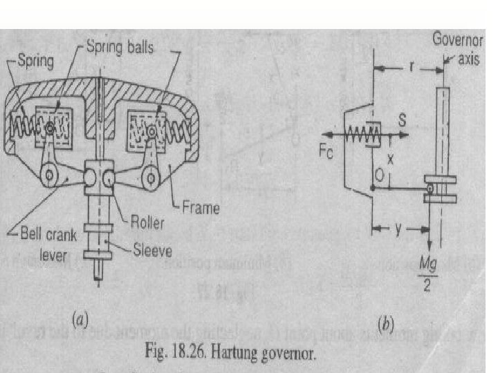
Hartung Governor
A spring controlled governor of Hartung type is shown in fig. In this type of governor, the vertical arms of the bell crank levers are fitted with spring balls which compress against the frame of the governor when the rollers at the horizontal arm press against the sleeve.
Let, S = Spring force Fc = Centrifugal force M = Mass of sleeve in kg. x & y = length of vertical and horizontal arm of the bell crank lever Final Equations: Fc x x = S x x + M. g 2 x y
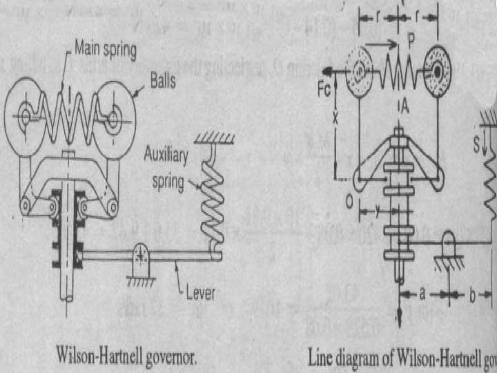
Wilson - Hartnell Governor
It is a governor in which the balls are connected by a spring in tension as shown. An auxiliary spring is attached to the sleeve mechanism, through lever by means of which equilibrium speed for a given radius may e adjusted. The main spring may e considered of two equal parts each belonging to both the balls.
Let, P = Tension in the main spring or ball spring A S = Tension in the auxiliary spring B m = mass of each ball M = Mass of sleeve in kg. r = Radius of rotation of each ball Sa = Stiffness of auxiliary spring Sb = Stiffness of each ball
Final Equations: 4 Sb Sb Fc 2 – Fc 1 = r 2 – r 1 = Fc 2 – Fc 1 4 (r 2 – r 1)
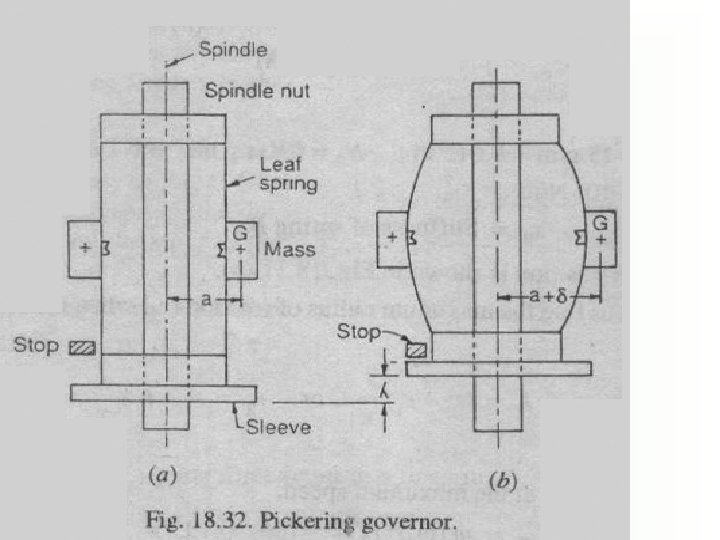
Pickering Governor
It is mostly used for driving gramophone. It consists of three straight leaf springs arranged at equal angular intervals round the spindle. Each spring carries a weight at the centre. The weights move outwards and the springs bend as they rotate about the spindle axis with increasing speed.
Let, m = Mass attached at the centre of the leaf spring a = Dist. From the spindle axis to the centre of gravity of the mass, when governor is at rest = Angular speed of the governor spindle = Deflection of centre of leaf spring at angular speed w 1 A + = Dist. from the spindle axis to the centre of gravity of the mass, when governor is rotating = Lift of the sleeve corresponding to the deflection
Final Equations: = m 2 (a + 192 E. I. ) L 3