Nuclear Medicine Physics Single Photon Emission Computed Tomography



- Slides: 51
Nuclear Medicine Physics • Single Photon Emission Computed Tomography (SPECT) Jerry Allison, Ph. D. Department of Radiology Medical College of Georgia
A note of thanks to Z. J. Cao, Ph. D. Medical College of Georgia And Sameer Tipnis, Ph. D. G. Donald Frey, Ph. D. Medical University of South Carolina for Sharing nuclear medicine presentation content
Tomographic NM imaging (SPECT) Single Photon Emission Computed Tomography 2015 Nuclear Medicine Physics for Radiology Residents Sameer Tipnis, Ph. D, DABR
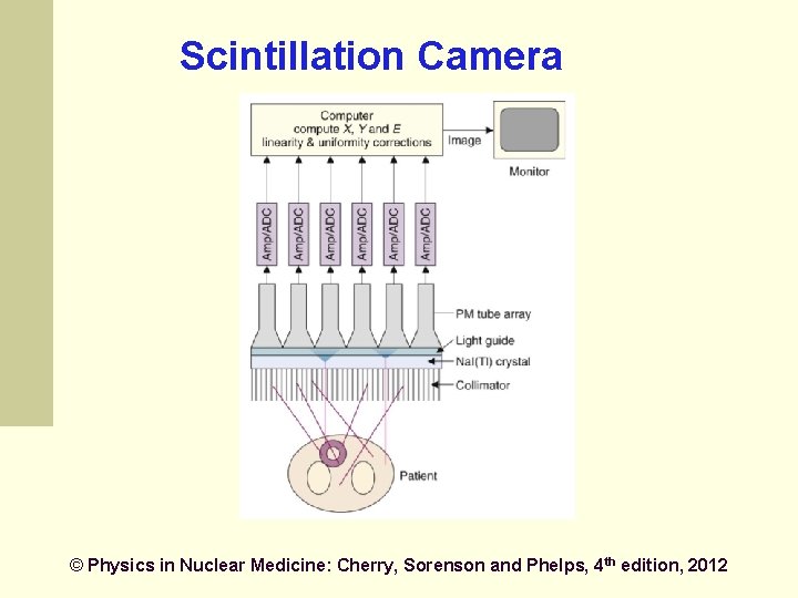
Scintillation Camera © Physics in Nuclear Medicine: Cherry, Sorenson and Phelps, 4 th edition, 2012
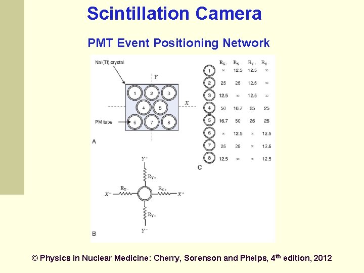
Scintillation Camera PMT Event Positioning Network © Physics in Nuclear Medicine: Cherry, Sorenson and Phelps, 4 th edition, 2012
Tomographic imaging (SPECT) Produce tomographic images by acquiring conventional gamma camera projection data at several angles around the patient Similar to CT Emission vs. transmission
SPECT Provide 3 -D images to eliminate overlaying and underlying activity of a slice better contrast more accurate lesion localization more demanding technically and longer data acquisition more severe image noise
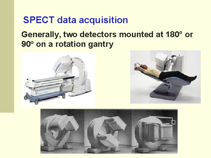
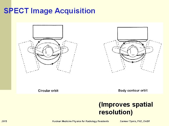
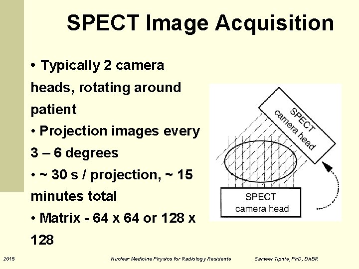
SPECT data acquisition Generally, two detectors mounted at 180 or 90 on a rotation gantry
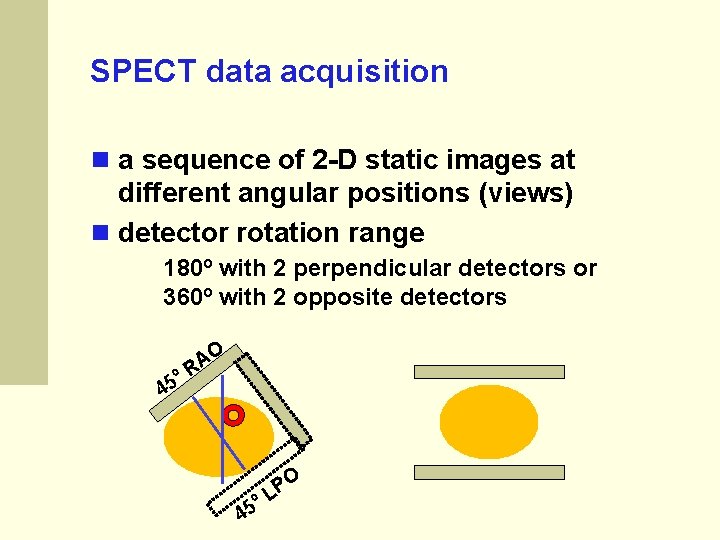
SPECT data acquisition a sequence of 2 -D static images at different angular positions (views) detector rotation range 180º with 2 perpendicular detectors or 360º with 2 opposite detectors 45 º O A R º 45 O P L
SPECT Image Acquisition (Improves spatial resolution) 2015 Nuclear Medicine Physics for Radiology Residents Sameer Tipnis, Ph. D, DABR
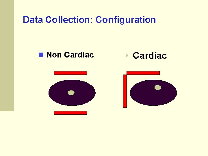
Data Collection: Configuration Non Cardiac • Cardiac
SPECT Image Acquisition • Typically 2 camera heads, rotating around patient • Projection images every 3 – 6 degrees • ~ 30 s / projection, ~ 15 minutes total • Matrix - 64 x 64 or 128 x 128 2015 Nuclear Medicine Physics for Radiology Residents Sameer Tipnis, Ph. D, DABR
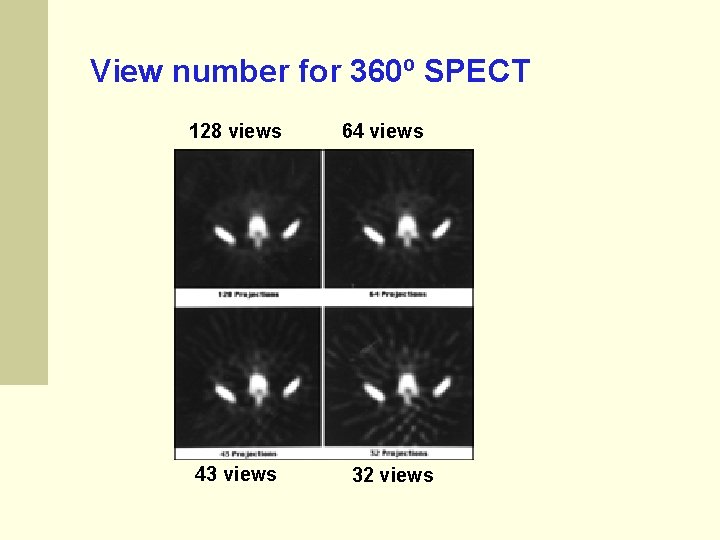
Data Collection: Angular Stops 3 to 6 degrees is common a lesser number causes streaking a larger number does not improve image quality Step-shoot or continuous acquisition, which is better? ? ? Step & Shoot Characteristics Some loss of time Less Blur
View number for 360º SPECT 128 views 43 views 64 views 32 views
An image with 128 x 128 matrix • Contains 128 projections • Each projection has 128 data points • Equivalent to 128 slice CT (i. e. , 128 tomographic slices per rotation) 2015 Nuclear Medicine Physics for Radiology Residents Sameer Tipnis, Ph. D, DABR
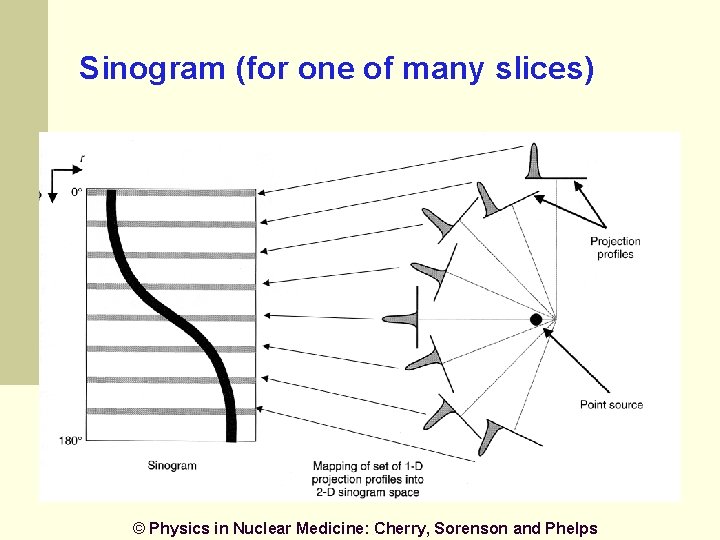
Sinogram (for one of many slices) © Physics in Nuclear Medicine: Cherry, Sorenson and Phelps
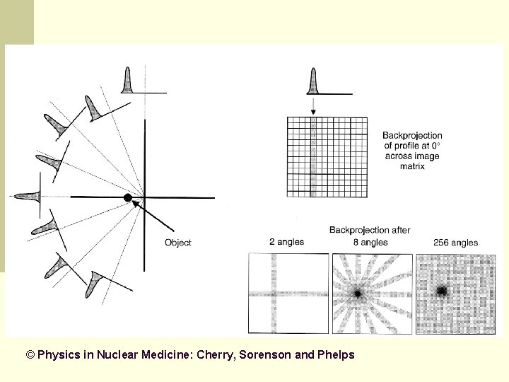
Back Projection of Sinogram Data Leads to blurring in image (streaks and star-like artifacts)
© Physics in Nuclear Medicine: Cherry, Sorenson and Phelps
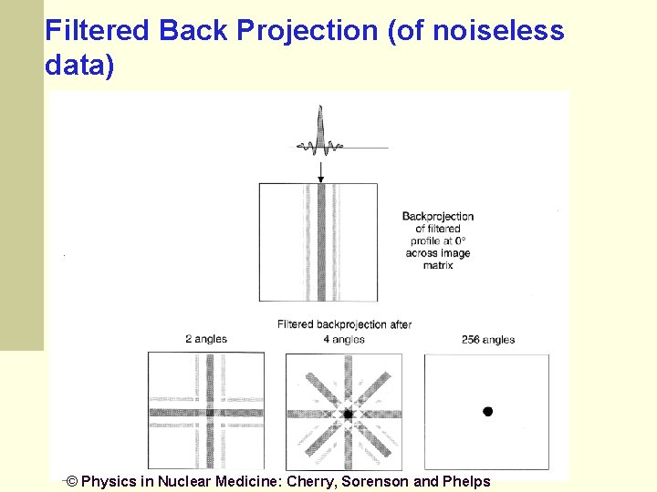
Filtered Backprojection Suppress blurring through filtering the projections A high-pass filter (ramp filter) can be used to suppress blurring
Filtered Back Projection (of noiseless data) © Physics in Nuclear Medicine: Cherry, Sorenson and Phelps
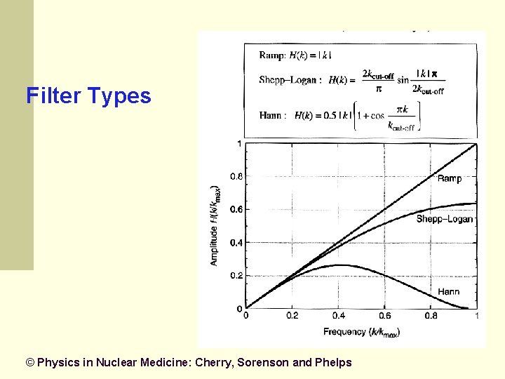
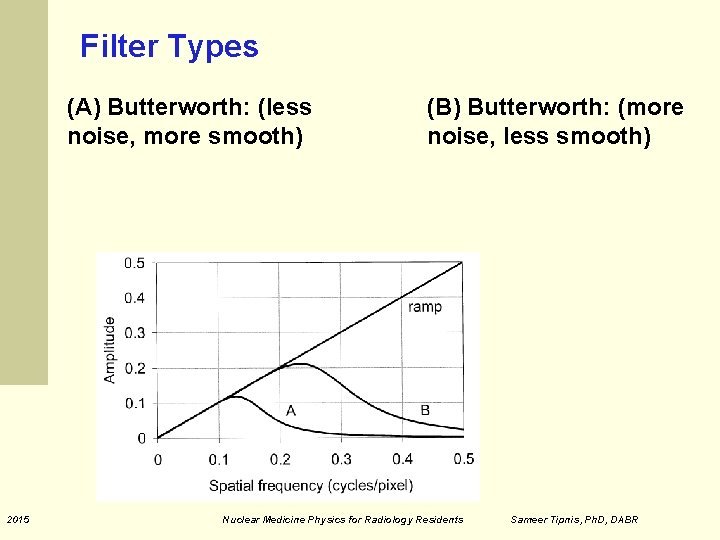
Filter Types © Physics in Nuclear Medicine: Cherry, Sorenson and Phelps
Filter Types (A) Butterworth: (less noise, more smooth) 2015 (B) Butterworth: (more noise, less smooth) Nuclear Medicine Physics for Radiology Residents Sameer Tipnis, Ph. D, DABR
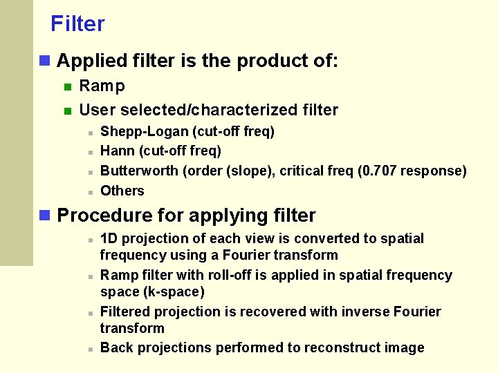
Filter Applied filter is the product of: Ramp User selected/characterized filter Shepp-Logan (cut-off freq) Hann (cut-off freq) Butterworth (order (slope), critical freq (0. 707 response) Others Procedure for applying filter 1 D projection of each view is converted to spatial frequency using a Fourier transform Ramp filter with roll-off is applied in spatial frequency space (k-space) Filtered projection is recovered with inverse Fourier transform Back projections performed to reconstruct image
Selection of Filters for SPECT Filters trade noise for resolution No standard way to optimize filter choice Patient to patient variation Physician preferences (and/or technologist) Vendor recommendation
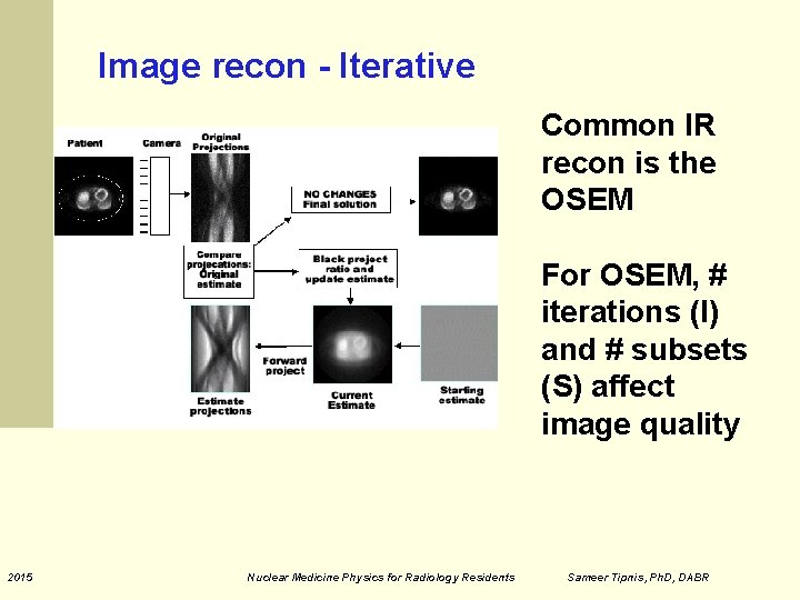
Iterative Reconstruction (IR) Filtered Back Projection has some limits Various corrections needed Attenuation Compton Scatter Ordered Subsets Expectation Maximization (OSEM) is a common iterative reconstruction algorithm
Iterative Reconstruction Slow compared to filtered back projection Commonly used for PET and SPECT and CT
Image recon - Iterative Common IR recon is the OSEM For OSEM, # iterations (I) and # subsets (S) affect image quality 2015 Nuclear Medicine Physics for Radiology Residents Sameer Tipnis, Ph. D, DABR
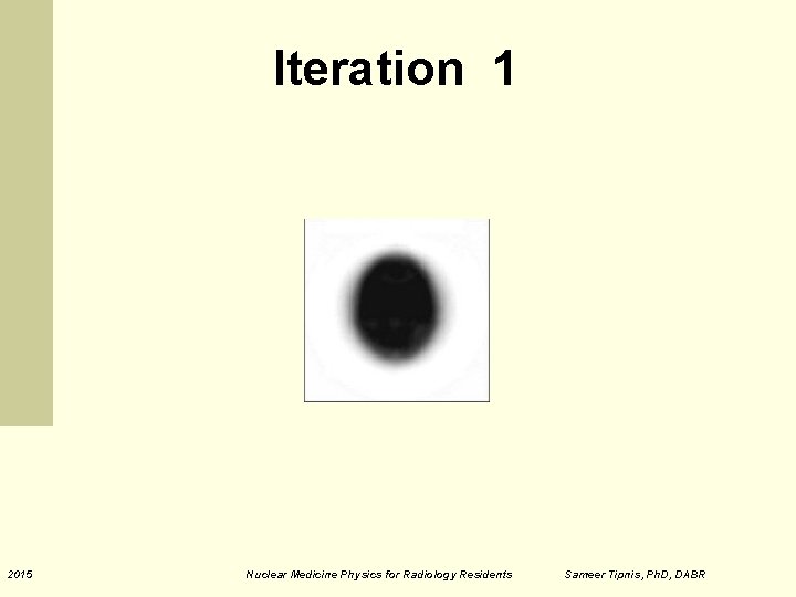
Iteration 1 2015 Nuclear Medicine Physics for Radiology Residents Sameer Tipnis, Ph. D, DABR
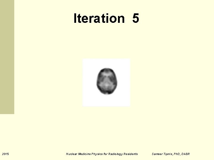
Iteration 5 2015 Nuclear Medicine Physics for Radiology Residents Sameer Tipnis, Ph. D, DABR
Iteration 10 2015 Nuclear Medicine Physics for Radiology Residents Sameer Tipnis, Ph. D, DABR
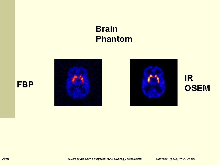
Brain Phantom IR OSEM FBP 2015 Nuclear Medicine Physics for Radiology Residents Sameer Tipnis, Ph. D, DABR
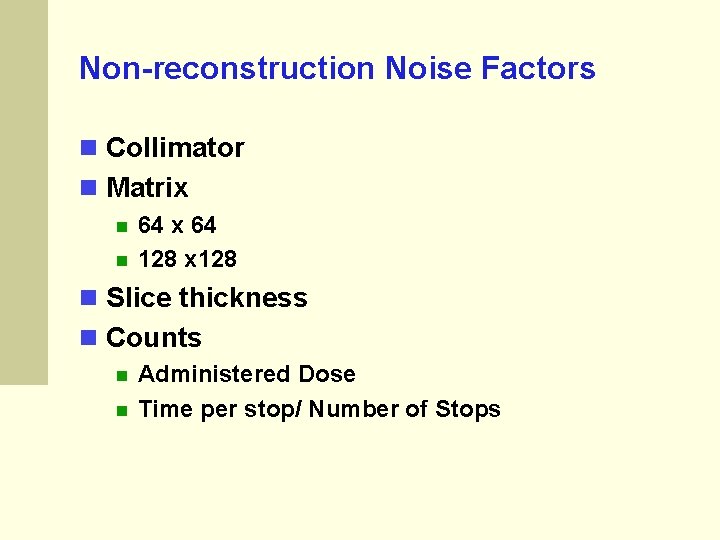
Non-reconstruction Noise Factors Collimator Matrix 64 128 x 128 Slice thickness Counts Administered Dose Time per stop/ Number of Stops
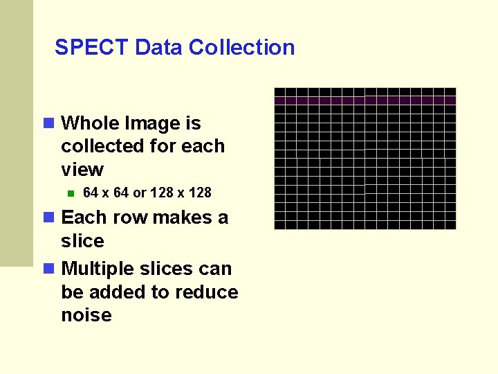
SPECT Data Collection Whole Image is collected for each view 64 x 64 or 128 x 128 Each row makes a slice Multiple slices can be added to reduce noise
Attenuation Correction Like all radionuclide imaging there is a problem due to attenuation. Correction can be important for judging the activity of lesions
Attenuation correction Gamma rays traveling smaller paths through the patient (nearer to camera) have less attenuation compared to those from deeper in patient for AC can be assumed or measured Chang (assumed) Measured - CT (new) CT can be non-diagnostic (low power, cone-beam) or fully diagnostic depending on the scanner model 2015 Nuclear Medicine Physics for Radiology Residents Sameer Tipnis, Ph. D, DABR
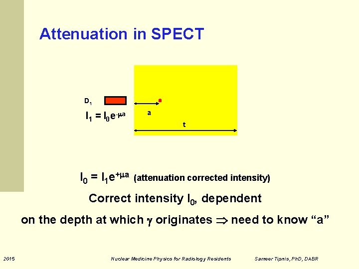
Attenuation in SPECT D 1 I 1 = I 0 e- a I 0 = I 1 e+ a a t (attenuation corrected intensity) Correct intensity I 0, dependent on the depth at which originates need to know “a” 2015 Nuclear Medicine Physics for Radiology Residents Sameer Tipnis, Ph. D, DABR
Chang’s AC method Image first reconstructed without AC To obtain contour of body Contours of image used to estimate attenuating depth for each pixel, assumed to be constant Attenuation correction (AC) determined for each pixel (x, y) for each projection Reconstructed image corrected pixel-by-pixel Works well for area with approximately constant attenuation like head, abdomen but not for areas like chest / thorax 2015 Nuclear Medicine Physics for Radiology Residents Sameer Tipnis, Ph. D, DABR
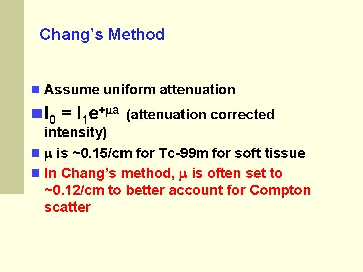
Chang’s Method Assume uniform attenuation I 0 = I 1 e+ a (attenuation corrected intensity) is ~0. 15/cm for Tc-99 m for soft tissue In Chang’s method, is often set to ~0. 12/cm to better account for Compton scatter
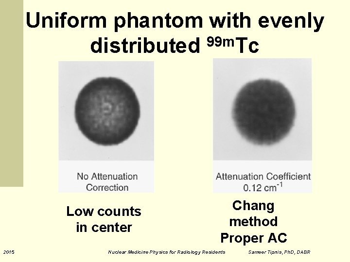
Uniform phantom with evenly distributed 99 m. Tc Low counts in center 2015 Chang method Proper AC Nuclear Medicine Physics for Radiology Residents Sameer Tipnis, Ph. D, DABR
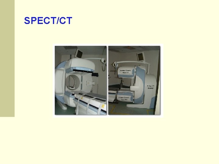
SPECT/CT
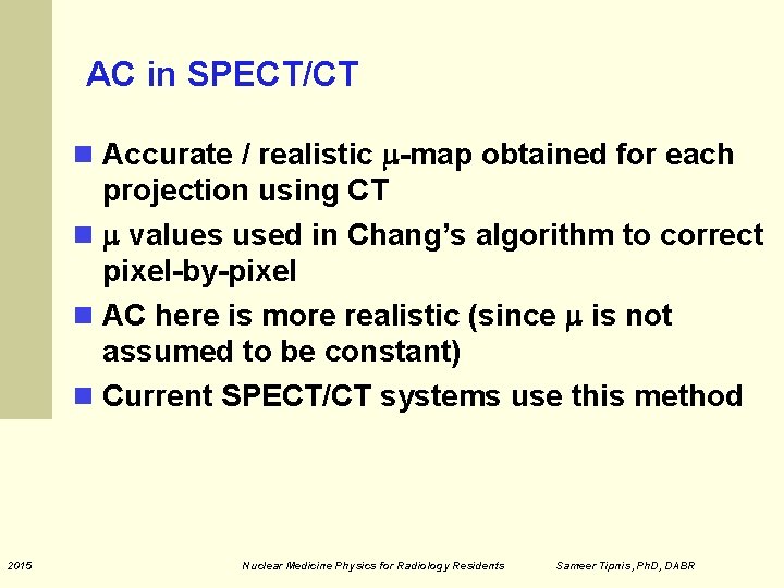
AC in SPECT/CT Accurate / realistic -map obtained for each projection using CT values used in Chang’s algorithm to correct pixel-by-pixel AC here is more realistic (since is not assumed to be constant) Current SPECT/CT systems use this method 2015 Nuclear Medicine Physics for Radiology Residents Sameer Tipnis, Ph. D, DABR
Philips Astonish NM Recon Software The Astonish: Ordered Subsets Expectation Maximization (OSEM) Compensation for the blurring effects of the collimator built into the reconstruction Resolution Recovery allows recovery of some of the original resolution Astonish uses the distance from the detector to the object of interest recorded as a function of angle by the camera during acquisition and geometric properties of the specific collimator
Philips Astonish NM Recon Software Used on essentially all Philips NM SPECT images at MCG Iterations: 4 Subsets: 16 On Bright. Views, CT data used for attenuation correction (except brains due to EEG electrode artifacts) Chang’s AC invoked for brains On Sky. Light and C-Cam, CT data not available
Common SPECT Problems Patient motion System Alignment (Center of rotation issues) Collimator issues Distance issues Loss of resolution with distance
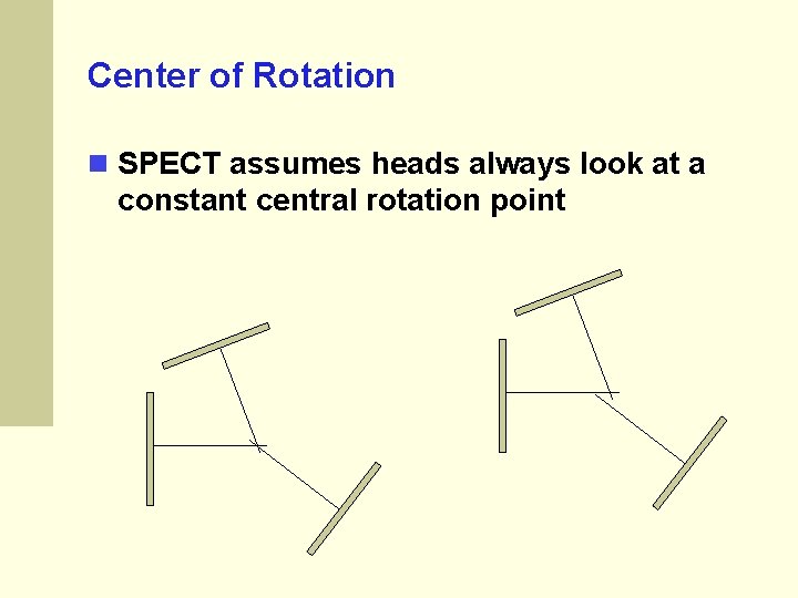
Center of Rotation SPECT assumes heads always look at a constant central rotation point
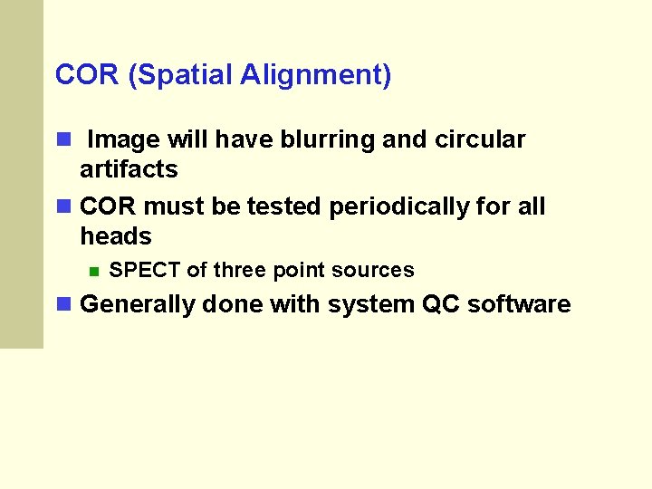
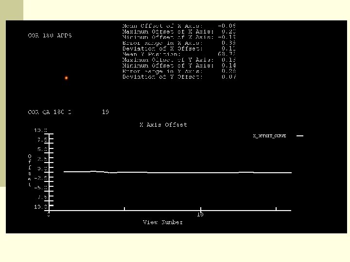
COR (Spatial Alignment) Image will have blurring and circular artifacts COR must be tested periodically for all heads SPECT of three point sources Generally done with system QC software
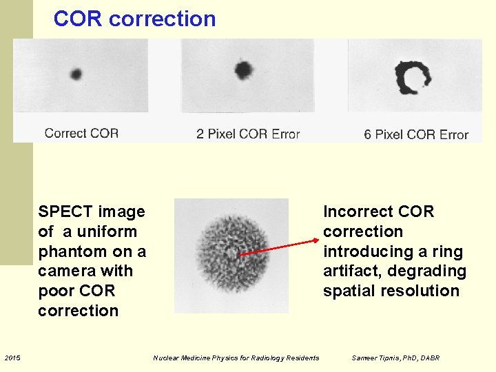
COR correction SPECT image of a uniform phantom on a camera with poor COR correction 2015 Incorrect COR correction introducing a ring artifact, degrading spatial resolution Nuclear Medicine Physics for Radiology Residents Sameer Tipnis, Ph. D, DABR
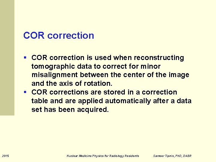
COR correction § COR correction is used when reconstructing tomographic data to correct for minor misalignment between the center of the image and the axis of rotation. § COR corrections are stored in a correction table and are applied automatically after a data set has been acquired. 2015 Nuclear Medicine Physics for Radiology Residents Sameer Tipnis, Ph. D, DABR
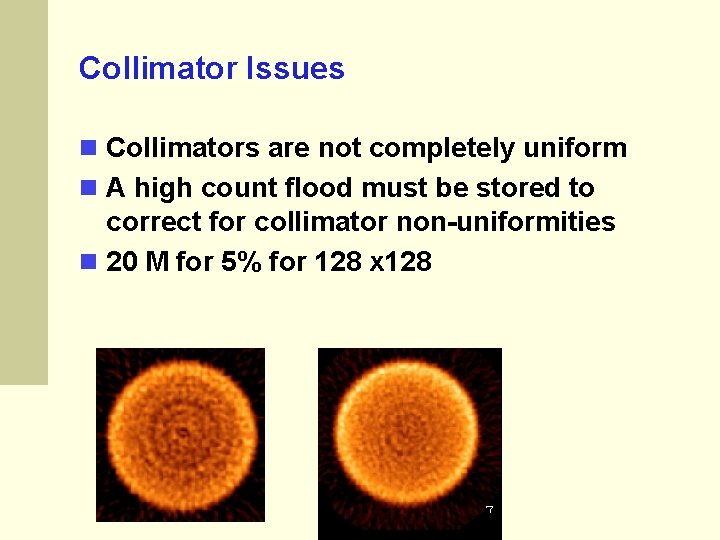
Collimator Issues Collimators are not completely uniform A high count flood must be stored to correct for collimator non-uniformities 20 M for 5% for 128 x 128
Patient Studies SPECT Advantages No overlapping structures 3 dimensional lesion locations Fusion with high resolution images (CT, MRI) Disadvantages Time consuming (motion) Images are noisy