MTIMoving Target Indication and PULSE DOPPLER RADAR Introduction
 and PULSE DOPPLER RADAR")


")


 The choice of operating with blind speeds or ambiguous")
 Double Cancellation: Single cancellers do not have a very")
 Double Cancellation: There are two implementations: n n These")
 Double Cancellation: 2/20/2021 38")


 Transversal Filters To obtain a frequency response of sinnπfd.")
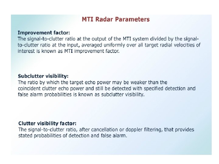
 Filter Performance Measures MTI Improvement Factor, IC Note that")
 Transversal Filters with Binomial Weighting with alternating sign Advantages:")
 Transversal Filters with Binomial Weighting with alternating sign Disadvantage:")
 Multiple PRFs An alternative is to use multiple PRFs")


 Frequency-response of a single-delay-line canceller for fp = 1/T 1;")
 response with periods in the ratio 25:")


- Slides: 82
MTI(Moving Target Indication) and PULSE DOPPLER RADAR
Introduction • Radars usually receive echoes scattered by natural environment as well as including land, sea and weather when detecting the targets in motion such as aircrafts or ships. • These echoes from the natural environment are called clutter, which creates confusion on the radar display. • When a clutter and target echo appear in the same radar resolution cell, it is difficult to distinguish the aircraft, because the magnitude of the strength of the clutter echoes is many times larger than the aircraft echoes. • The most efficient technique for detecting moving targets when there is large clutter is Doppler processing.
• Relative motion between radar and the moving target then there is a change in the frequency of the radar echo signal which is called Doppler shift. • The Doppler frequency shift is used to remove clutter from the moving targets depending upon their velocity differences. • The pulse radar that uses the Doppler shift is either moving target indication radar or pulse Doppler radar • MTI radar is used to detect the targets in presence of large clutter. Pulse Doppler radar when used along with MTI can measure Doppler shift and radial velocity of the target. • The working principle of both radars depends upon the predetermined time delay produced by the echoes from stationary targets return towards the receiver.
Introduction to Pulse, MTI and pulse Doppler Radars Pulse Radars: Transmits high frequency pulse (signal) and receive the corresponding echoes before a new transmitted signal is sent out. Determine azimuth, elevation and range of the target from the measured antenna position and propagation time of the pulse. Direction, distance and the altitude of the target can also be found Ex: Weather Radars MTI Radar: Main objective is to reject the signals from stationary unwanted signals i. e. , ground clutter, rain clutter, bird clutter etc. , that arrive as echo along with the desired echo of the signal. The processing system is used to eliminate unwanted clutter from the background and to detect moving targets even when the velocity of such targets is small relative to the radar platform.
Two basic types of MTI radar 1. Coherent MTI 2. Non-Coherent MTI In coherent systems the receiver preserves the transmitted wave’s phase in order to detect the Doppler shift in frequency. Doppler shift in the echo signal from the moving target is used to differentiate it from stationary target. In non-coherent MTI systems the moving targets can be detected by observing the relative motion between the target and clutter background, and also by observing corresponding changes in amplitudes of pulses. Coherent detection requires dealing with envelope of signal and the phase of the sinusoidal carrier. They measured indirectly from inphase (I) and quadrature (Q) channels
Pulse Doppler Radars: compared to MTI, it is more advanced system. Pulse radar system makes use of Doppler effect to obtain target information (velocity and amplitude) but not for clutter rejection purposes. The difference between pulse Doppler radars and conventional pulse radars is blind speeds can be reduced by using high PRF rates.
MTI RADAR PULSE DOPPLER RADAR 1. Pulse radar that uses the Doppler frequency shift to differentiate moving target from fixed targets, operate at lower target from fixed targets, operate at high PRFs (< 4 KHz) and provide more PRFs (>100 KHz), and provide better accurate range resolution velocity discrimination and clutter 2. MTI techniques only separate moving rejection targets from clutter. 2. Besides eliminating clutter it also separates targets into different velocity regimes 3. Does not provide target velocity 3. Provides good estimates of target velocity estimation 4. Uses short waveforms (two or three 4. Uses long waveforms (many pulses, tens pulses) to thousands of pulses) 5. Has ambiguous Doppler measurement 5. PRF is high enough to operate with which is called blind speeds and unambiguous Doppler (no blind speeds) unambiguous range measurement i. e. no but at the expense of range ambiguities second time around echoes 6. MTI radar uses magnetron oscillator as a 6. Uses klystron oscillator as a source 7. Generally uses delay line cancellers 7. Generally uses range gated Doppler filters
Introduction to MTI Radar : • MTI Radar means Moving Target Indication Radar. • This is one form of pulsed radar • MTI radar is characterized by its very low pulse repetition frequency and hence there is no range ambiguity in MTI Radar. • The unambiguous range is given by R (un)= C/2 fp fp= pulse repetition frequency C=velocity of electromagnetic wave in free space. • At the same time , MTI Radar has many ambiguities in the Doppler domain. • It determines target velocity and distinguishes moving targets from stationary targets.
Principle of Operation
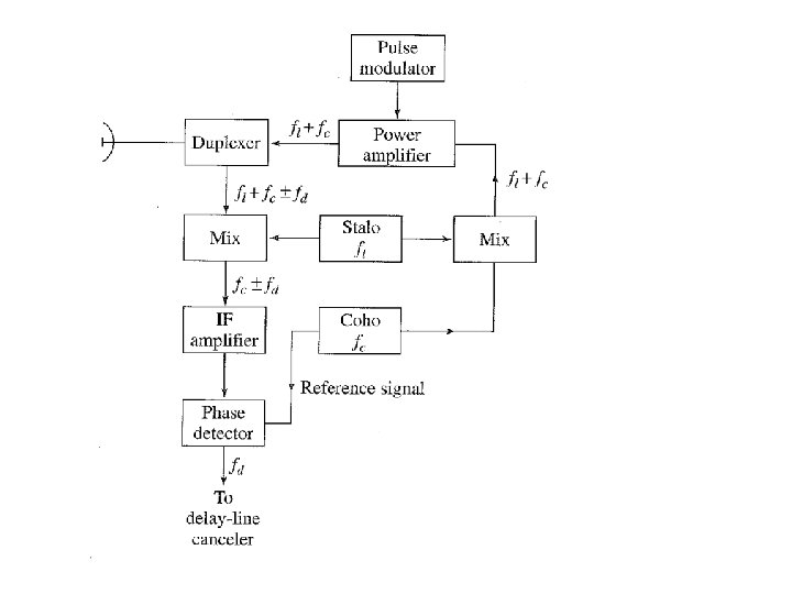
MTI Radar with Power Amplifier Transmitter : • The radar which uses the concept of Doppler frequency shift for distinguishing desired moving targets from stationary objects i. e. , clutter is called as MTI radar (Moving Target Indicator). • The block diagram of MTI radar employing a power amplifier is shown in Fig. • The significant difference between this MTI configuration and that of Pulse Doppler radar is the manner in which the reference signal is generated. • Here the coherent reference is supplied by an oscillator called the coho, which stands for coherent oscillator. • The coho is a stable oscillator whose frequency is the same as the intermediate frequency used in the receiver.
• In addition to providing the reference signal, the output of the coho fc is also mixed with the local-oscillator frequency fl. • The local oscillator must also be a stable oscillator and is called stalo, for stable local oscillator. • The RF echo signal is heterodyned with the stalo signal to produce the IF signal, just as in the conventional superheterodyne receiver. • The stalo, coho, and the mixer in which they are combined plus any low-level amplification are called the receiverexciter • because of the dual role they serve in both the receiver and the transmitter.
• The characteristic feature of coherent MTI radar is that the transmitted signal must be coherent (in phase) with the reference signal in the receiver. • This is accomplished by generating the transmitted signal from the coho reference signal. • The function of the stalo is to provide the necessary frequency translation from the IF to the transmitted (RF) frequency. • Although the phase of the stalo influences the phase of the transmitted signal, any stalo phase shift is canceled on reception because the stalo that generates the transmitted signal also acts as the local oscillator in the receiver.
• The reference signal from the coho and the IF echo signal are both fed into a mixer called the phase detector • The phase detector differs from the normal amplitude detector since its output is proportional to the phase difference between the two input signals. • Any one of a number of transmitting-tube types might be used as the power amplifier. • These include the triode, tetrode, klystron, traveling-wave tube, and the crossed-field amplifier.
MTI Radar with Power oscillator Transmitter
Stable low-power oscillator followed by a power amplifier is sometimes called MOPA, which stands for master-oscillator power amplifier. Before the development of the klystron amplifier, the only high-power transmitter available at microwave frequencies for radar application was the magnetron oscillator. In an oscillator the phase of the RF bears no relationship from pulse to pulse. For this reason the reference signal cannot be generated by a continuously running oscillator. coherent reference signal may be readily obtained with the power oscillator by readjusting the phase of the coho at the beginning of each sweep according to the phase of the transmitted pulse.
• The phase of the coho is locked to the phase of the transmitted pulse each time a pulse is generated. • A portion of the transmitted signal is mixed with the stalo output to produce an IF beat signal whose phase is directly related to the phase of the transmitter. • This IF pulse is applied to the coho and causes the phase of the coho CW oscillation to "lock" in step with the phase of the IF reference pulse. • The phase of the coho is then related to the phase of the transmitted pulse and may be used as the reference signal for echoes received from that particular transmitted pulse. • Upon the next transmission another IF locking pulse is generated to relock the phase of the CW coho until the next locking pulse comes along
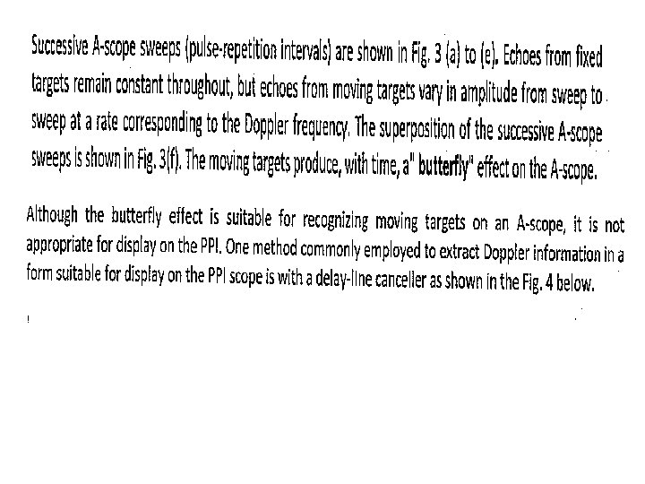
Delay line canceller or Pulse cancellers • Delay line canceller is also known as transversal filter or tapped delay line filter or non-recursive filter of moving average filter or finite impulse response filter. • For moving targets, the amplitude continuously changes due to Doppler frequency shift. So for each pulse the amplitude varies. While filtering one pulse is subtracted from the other pulse. • Due to subtraction of pulses, fixed clutter echoes are cancelled and they are not detected ; where as moving target echoes, they are not cancelled and are detected. • To implement the above reasoning , a single delay line canceller, also referred to as the two-pulse MTI canceller of first order canceller, is used to eliminate the clutter.
• If one sweep is subtracted from the previous sweep, fixed clutter will cancel and will not be detected or displayed. • Moving targets change in amplitude from sweep to sweep because of their Doppler frequency shift. If one sweep is subtracted from the other, the result will be an uncancelled resude.
Subtraction of the echoes from two successive sweeps is accomplished in a delay line canceller. Output of MTI receiver is digitized and the input to the delay line canceller (performs the role of Doppler shift). The delay T is achieved by storing the radar output from one pulse transmission or sweep, in a digital memory for a time equal to the pulse repetition period so that T=Tp=1/fp.
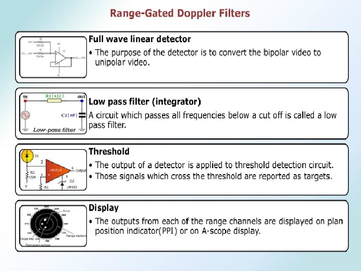
• The output obtained after subtraction of two successive sweeps is bipolar (digital) video since the clutter echoes in the output contain both positive and negative amplitudes. • It is usually called video, even though it is a series of digital words rather than an analog video signal. • The absolute value of the bipolar video is taken which is then unipolar video. • Unipolar video is needed if an analog display is used that requires positive signals only. • Unipolar video is converted to an analog signal by D/A converter if the processed signal is to be displayed on PPI. • Then digital signal may be used for automatically making the detection decision.
Filter characteristics of the delay-line canceller • Filter characteristics of the delay-line canceller. The delay-line canceller acts as a filter which rejects the d-c component of clutter. • The delay line canceller is a time domain filter. It rejects stationary clutter at zero frequency. Its frequency response function is derived from the signals in time domain. • The video signal received from a particular target at a range R 0 is V 1 = k sin (2πfdt – φ0) Where, φ0 = phase shift k = amplitude of video signal • The signal from the previous transmission, which is delayed by a time T = pulse repetition interval, is V 2 = k sin (2πfd(t – T) – φ0)
• Everything else is assumed to remain essentially constant over the interval T , so that k is the same for both pulses. • The output from the subtractor is V = V 1 – V 2 = 2*k sin πfd. T cos [2πfd(t – T / 2) - φ0] • It is assumed that the gain through the delay-line canceller is unity. • The output from the canceller consists of a cosine wave with same Doppler frequency fd as the input, but with an amplitude 2 k sin( πfd. T). • Thus the amplitude of the canceled video output depends upon the Doppler frequency shift and the pulse-repetition interval, or prf. • The frequency response function of the single delay line canceller (output amplitude divided by the input amplitude k) is H(f)=2* sin(πfd. T)
The single delay line eliminates fixed clutter that is of zero Doppler frequency. Two other properties that can seriously limit the utility of Doppler filter 1. Frequency response function also has zero response when moving targets have Doppler frequencies at the prf and its harmonics 2. Clutter spectrum at zero frequency is not a delta function of zero width, but has finite width so that clutter will appear in the pass band of the delay line canceller. The result is there will be target speed called blind speeds, where the target will not be detected and there will be an uncanceled clutter residue that can interfere with the detection of moving targets
Blind Speeds • Definitions • Blind speed is defined as the radial velocity of the target at which the MTI is zero • It is also defined as the radial velocity of the target which results in a phase difference of exactly 2Π radians between successive pulses • Blind speed is defined as the radial velocity of the target at which no shift appears making the target appearing stationary and echoes from the target are cancelled
Blind Speeds • Blind speeds: response of the single delay-line will be zero whenever the magnitude of sin(πfd. T) is zero, which occurs when πfd. T =0, ±π, ± 2π…. . • where n= 0, 1, 2, . . . , and fp = pulse repetition frequency. • The delay-line canceller not only eliminates the d-c component caused by clutter (n = O), but unfortunately it also rejects any moving target whose Doppler frequency happens to be the same as the prf or a multiple thereof. • Those relative target velocities which result in zero MTI response are called blind speeds
• Blind speed is defined as the radial velocity of the target at which the MTI response is zero. • It is also defined as the radial velocity of the target which results in a phase difference of exactly 2π radians between successive pulses. • Blind speed is defined as the radial velocity of the target at which no shift appears making the target appearing stationary and echoes from the target are cancelled. • The blind speed of the target is given by, fd = n / T = n fp
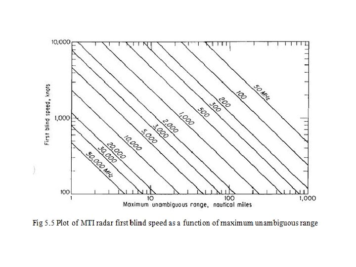
where , vn is the nth blind speed. fp = pulse repetition frequency. n=0, 1, 2, 3…. . λ = wavelength • If λ is measured in meters, fp in Hz, and the relative velocity in knots, the blind speeds are • The blind speeds are one of the limitations of pulse MTI radar which do not occur with CW radar. They are present in pulse radar because doppler is measured by discrete samples (pulses) at the PRF rather than continuously. • If the first blind speed is to be greater than the maximum radial velocity expected from the target, the product λfp must be large. • Thus the MTI radar must operate at long wavelengths (low frequencies) or with high pulse repetition frequencies
Moving Target Indicator Radar (MTI) The choice of operating with blind speeds or ambiguous ranges depends on the application Two ways to mitigate the problem at the expense of increased complexity are: a. operating with multiple prfs b. operating with multiple carrier frequencies 2/20/2021 35
Moving Target Indicator Radar (MTI) Double Cancellation: Single cancellers do not have a very sharp cutoff at the nulls which limits their rejection of clutter (clutter does not have a zero width spectrum) Adding more cancellers sharpens the nulls 2/20/2021 36
Moving Target Indicator Radar (MTI) Double Cancellation: There are two implementations: n n These have the same frequency response: which is the square of the single canceller response 2/20/2021 37
Moving Target Indicator Radar (MTI) Double Cancellation: 2/20/2021 38
The output of the two single-delay- line cancellers in cascade is the square of that from a single canceller. • The frequency response is 4 sin 2 πfd. T. The configuration of Fig. is called a double-delay-line canceller, or simply a double canceller. • The relative response of the double canceller compared with that of a single-delay-line canceller is shown in Fig. • The finite width of the clutter spectrum is also shown in this figure so as to illustrate the additional cancellation of clutter offered by the double canceller.
• The two-delay-line configuration of Fig. 1 has the same frequency-response characteristic as the double-delay-line canceller. • The operation of the device is as follows. A signal f (t) is inserted into the adder along with the signal from the preceding pulse period, with its amplitude weighted by the factor - 2, plus the signal from two pulse periods previous. Three pulses are added with appropriate weights +1, -2, +1, The output of the adder is therefore f(t) – 2 f(t - T) + f(t - 2 T) which is the same as the output from the double-delay-line canceller f(t) – f(t - T) - f(t -T) + f(t - 2 T) This configuration is commonly called the three-pulse canceller
Thus double and three pulse canceller has the same frequency response function. A four pulse canceller with weights +1, -3, +3, -1 has frequency response proportional to sin 3 πfd. T A five pulse canceller has weights +1, -4, +6, -4, +1. If n is the number of delay lines, there are n+1=N pulses available to produce frequency response function to sinnπfd. T, the weights are the coefficients of the expansion of the binomial series with alternate signs. (1 -x)n
Moving Target Indicator Radar (MTI) Transversal Filters To obtain a frequency response of sinnπfd. T, the taps must be binomially weighted i. e. 2/20/2021 42
Moving Target Indicator Radar (MTI) Filter Performance Measures MTI Improvement Factor, IC Note that this is averaged over all Doppler frequencies Signal Clutter Filter 0 1/2 T 2/20/2021 0 1/2 T 43
Moving Target Indicator Radar (MTI) Transversal Filters with Binomial Weighting with alternating sign Advantages: - Close to optimum for maximizing the Clutter improvement factor - Also close to maximizing the Clutter Attenuation Cin/Cout 2/20/2021 44
Moving Target Indicator Radar (MTI) Transversal Filters with Binomial Weighting with alternating sign Disadvantage: - As n increases the sinn filter cuts off more and more of the spectrum around DC and multiples of PRF - This leads to wider blind speed zones and hence loss of legitimate targets. 2/20/2021 45
Moving Target Indicator Radar (MTI) Multiple PRFs An alternative is to use multiple PRFs because the blind speeds (and hence the shape of the filter response) depends on the PRF and, combining two or more PRFs offers an opportunity to shape the overall response. 2/20/2021 46
Staggered PRF’s • The pulse repetition frequency in which the switching is pulse to pulse is known as “Staggered PRF”. • The use of more than one pulse repetition frequency offers additional flexibility in the design of MTI Doppler filters. • It not only reduces the effect of the blind speeds but it also allows a sharper low-frequency cutoff in the frequency response than might be obtained with a cascade of single-delay-line cancellers with sinn πfd. T response.
• The blind speeds of two independent radars operating at the same frequency will be different if their pulse repetition frequencies are different. • if one radar were blind to moving targets, it would be unlikely that the other radar would be blind also. • Instead of using two separate radars, the same result can be obtained with one radar which time-shares its pulse repetition frequency between two or more different values (multiple PRF's).
• The pulse repetition frequency might be switched every other scan or every time the antenna is scanned a half beam width, or the period might be alternated on every other pulse. • When the switching is pulse to pulse, it is known as a staggered prf. • An example of the composite (average) response of an MTI radar operating with two separate pulse repetition frequencies on a timeshared basis is shown in Fig. . The pulse repetition frequencies are in the ratio of 5 : 4. • Note that the first blind speed of the composite response is increased several times over what it would be for a radar operating on only a single pulse repetition frequency. • Zero response occurs only when the blind speeds of each prf coincide. In the example of Fig. , the blind speeds are coincident For 4/T 1 = 5/T 2.
Fig 5. 11 (a) Frequency-response of a single-delay-line canceller for fp = 1/T 1; (b) same for fp = 1/T 2 (c) composite response with 4/T 1 = 5/T 2.
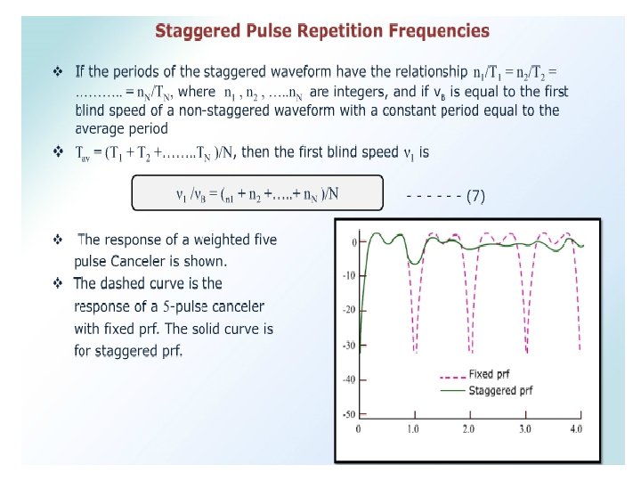
shows a five pulse stagger (4 periods) response with periods in the ratio 25: 30: 27: 31 In this example the periods are in the ratio 25 : 30 : 27 : 31 and the first blind speed is 28. 25 times that of a constant prf waveform with the sameaverage period.
• The closer the ratio T 1: T 2 approaches unity, the greater will be the value of the first blind speed. However, the first null in the vicinity of fd = l/T 1 becomes deeper. • Thus the choice of T 1 /T 2 is a compromise between the value of the first blind speed and the depth of the nulls within the filter pass band. • The depth of the nulls can be reduced and the first blind speed increased by operating with more than two interpulse periods. • A disadvantage of the staggered prf is its inability to cancel second-timearound clutter echoes. • Such clutter does not appear at the same range from pulse to pulse and thus produces un canceled residue. • Second-time-around clutter echoes can be removed by use of a constant prf. providing there is pulse-to-pulse coherence as in the power amplifier form of MTI.
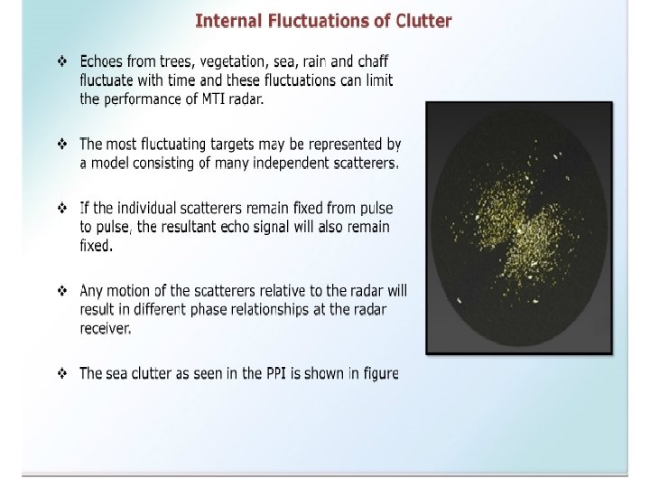
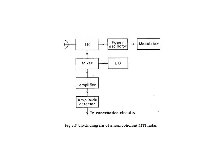
Non-Coherent MTI Radar • The composite echo signal from a moving target and clutter fluctuates in both phase and amplitude. • The coherent MTI and the pulse-doppler radar make use of the phase fluctuations in the echo signal to recognize the doppler component produced by a moving target. • In these systems, amplitude fluctuations are removed by the phase detector. • The operation of this type of radar, which may be called coherent MTI, depends upon a reference signal at the radar receiver that is coherent with the transmitter signal.
• It is also possible to use the amplitude fluctuations to recognize the doppler component produced by a moving target. • MTI radar which uses amplitude instead of phase fluctuations is called non coherent. It has also been called externally coherent. • The non-coherent MTI radar does not require an internal coherent reference signal or a phase detector as does the coherent form of MTI. • Amplitude limiting cannot be employed in the non-coherent MTI receiver, else the desired amplitude fluctuations would be lost.
• Therefore the IF amplifier must be linear, or if a large dynamic range is required, it can be logarithmic. • The detector following the IF amplifier is a conventional amplitude detector. • The phase detector is not used since phase information is of no interest to the non-coherent radar. • The local oscillator of the non-coherent radar does not have to be as frequency-stable as in the coherent MTI. • The output of the amplitude detector is followed by an MTI processor such as a delay-line canceller. • The doppler component contained in the amplitude fluctuations may also be detected by applying the output of the amplitude detector to an A-scope.
• The advantage of the non-coherent MTI is its simplicity; hence it is attractive for those applications where space and weight are limited. • Moving targets can be detected by observing relative motion between the target and clutter background, and by observing corresponding changes in amplitudes of pulses.
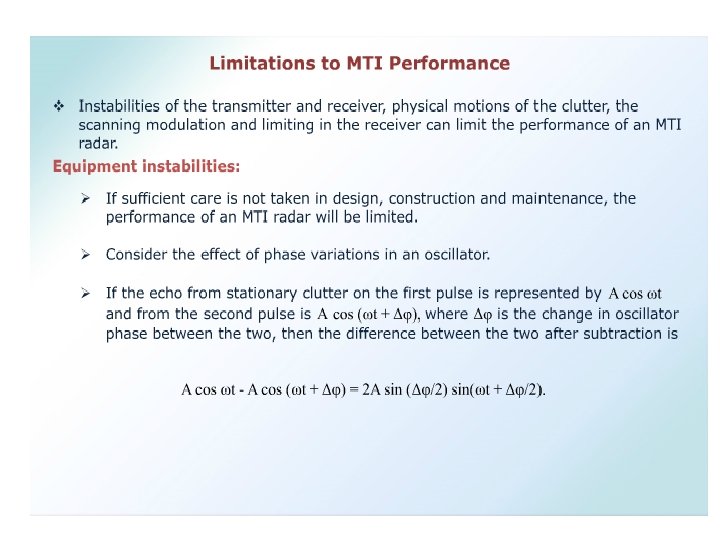
Limitations to MTI Performance Limitations of MTI Radar : 1. Equipment instabilities. 2. Scanning modulation. Equipment instabilities : • Pulse-to-pulse changes in the amplitude, frequency, or phase of the transmitter signal, changes in the stalo or coho oscillators in the receiver, jitter in the timing of the pulse transmission, variations in the time delay through the delay lines • changes in the pulse width can cause the apparent frequency spectrum from perfectly stationary clutter to broaden and thereby lower the improvement factor of an MTI radar.
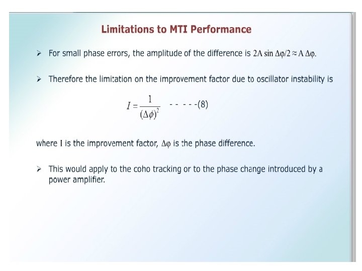
• The stability of the equipment in a MTI radar must be considerably better than that of an ordinary radar. • It can limit the performance of the MTI radar if sufficient care is not taken in design, construction, and maintenance. • Echo received from the fist pulse from stationary clutter is represented by A cos (w t + φ) • If the echo from stationary the second pulse is A cos (w t + φ+ ∆φ ) , then there will be an uncanceled reside from a single delay line canceller equal to the difference 2 A sin (∆φ /2) • where ∆φ is the change phase change between the pulses. For small phase errors, the amplitude of the resultant difference is A ∆φ. • Clutter attenuation is 1 / ∆φ2 and the improvement factor is twice this.
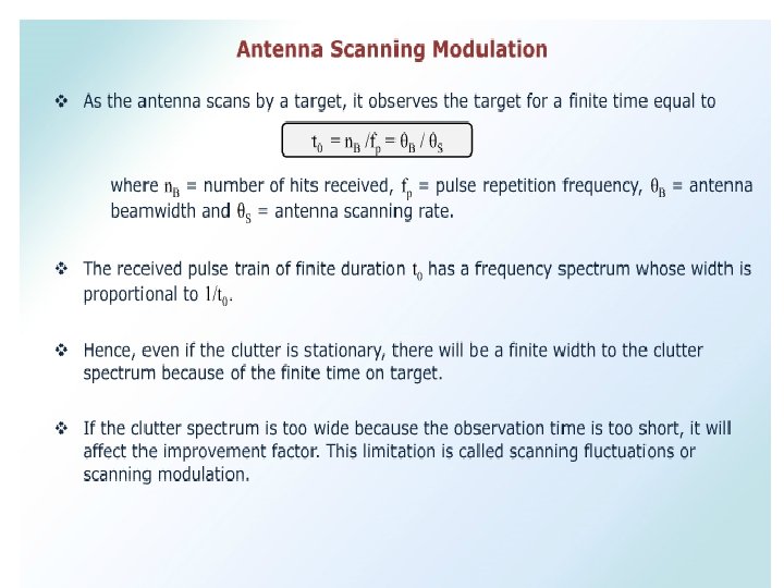
Scanning modulation : • As the antenna scans by a target, it observes the target for a finite time equal to t 0 = n. B / fp = θB / θS where, n. B = number of hits received, fp = pulse repetition frequency, θB = antenna beam width and θS = antenna scanning rate. • The received pulse train of finite duration to has a frequency spectrum whose width is proportional to l/t 0. • Therefore, even if the clutter were perfectly stationary, there will still be a finite width to the clutter spectrum because of the finite time on target. • If the clutter spectrum is too wide because the observation time is too short, it will affect the improvement factor. This limitation has sometimes been called scanning fluctuations or scanning modulation.
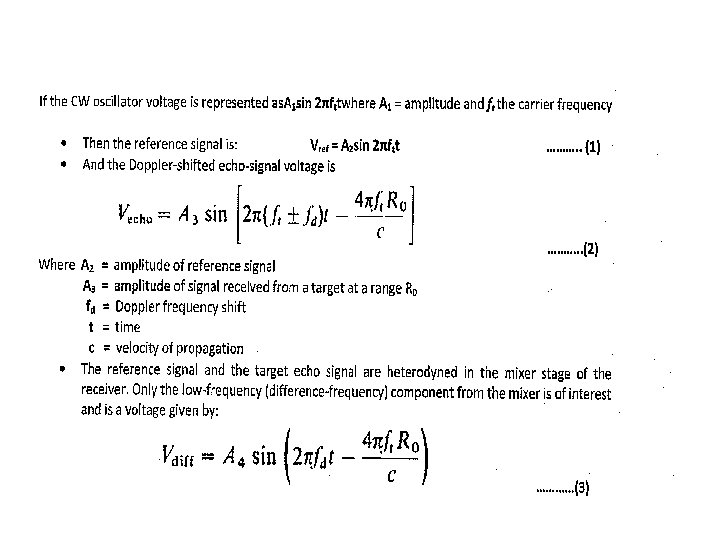
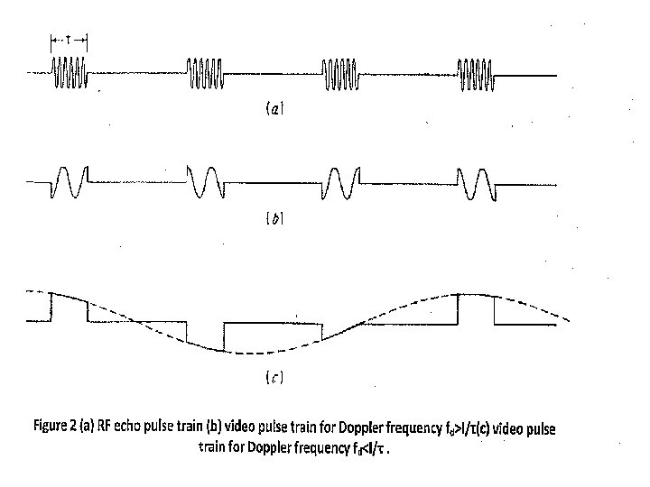
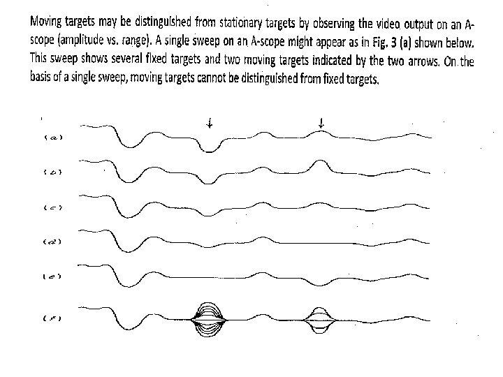
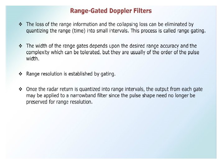
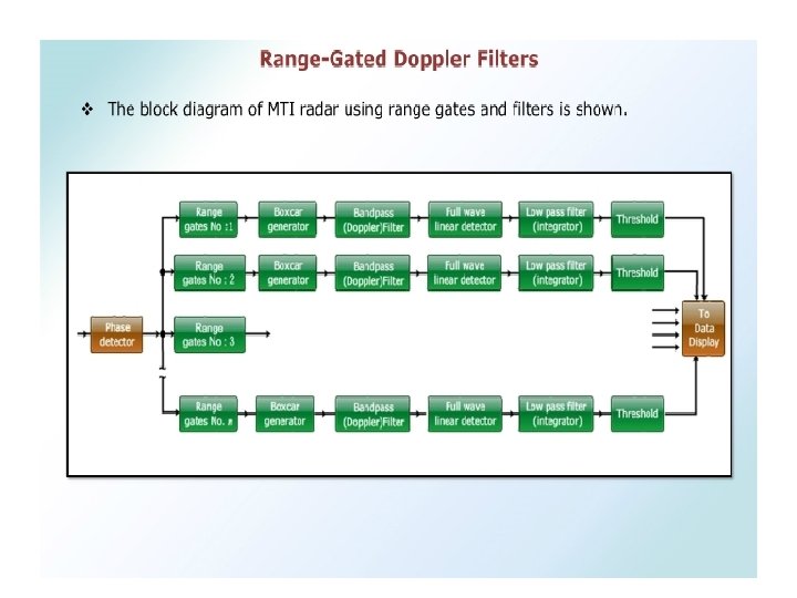
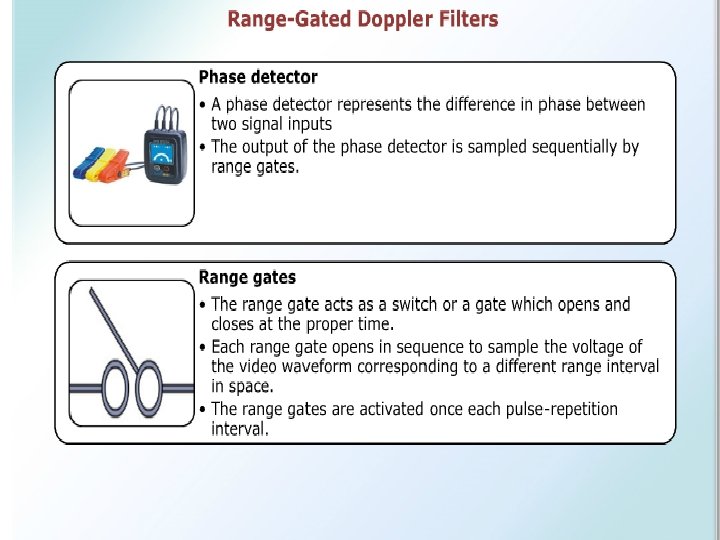
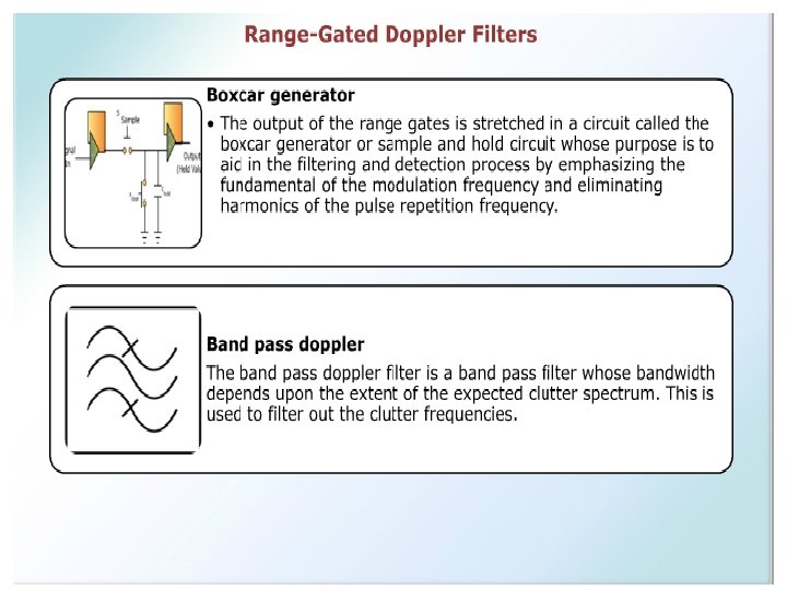
MTI vs. Pulse Doppler Radar