Magnetic Pulsed Valve 1 The valve opens and


- Slides: 39
Magnetic Pulsed Valve
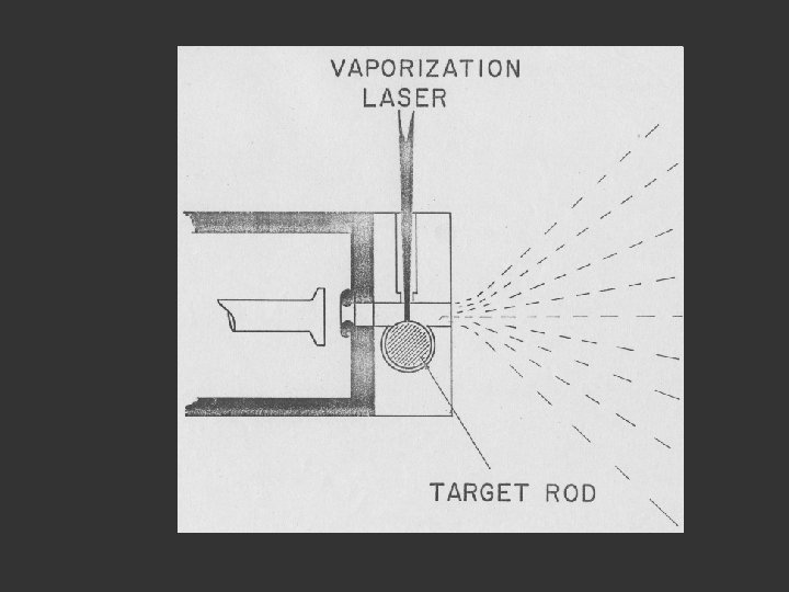
1. The valve opens and shuts Lens to focus the laser beam Pulsed Valve Rotating Disk He
1. The valve opens and shuts Lens to focus the laser beam 2. A helium pulse passes along the tube Pulsed Valve Rotating Disk He
1. The valve opens and shuts Lens to focus the laser beam 2. A helium pulse passes along the tube 3. The laser fires to produce a plasma of atoms (ca 10 000 o) Pulsed Valve Rotating Disk He
1. The valve opens and shuts Lens to focus the laser beam 2. A helium pulse passes along the tube 3. The laser fires to produce a plasma of atoms (ca 10 000 o) Pulsed Valve 4. The atoms cluster as they cool 5. and are swept into the vacuum chamber Rotating Disk He
Skimmer hole into TOF-MS Time of Flight mass spectrometer Plasma beam expanding into the first vacuum chamber disk
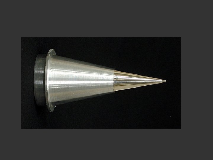
Supersonic Expansion into the vacuum chamber cools the clusters to very low temperatures The very sharp edged skimmer skims the expanding pulse into a very narrow beam
Skimmer action more slowly
Time of flight mass spectrometer TOF-MS Detector -ve grid
Time of flight mass spectrometer TOF-MS Detector 1. The pulse arrives at the bottom of the flight tube -ve grid
Time of flight mass spectrometer TOF-MS Detector 1. The pulse arrives at the bottom of the flight tube 2. A laser fires 3. Ionises the molecules or clusters -ve grid
Time of flight mass spectrometer TOF-MS Detector 1. The pulse arrives at the bottom of the flight tube 2. A laser fires 3. Ionises the molecules or clusters 4. The ions are accelerated up the flight tube by the negatively charged grid -ve grid
Time of flight mass spectrometer TOF-MS Detector 1. The pulse arrives at the bottom of the flight tube 2. A laser fires 3. Ionises the molecules or clusters 4. The ions are accelerated up the flight tube by the negatively charged grid 5. Light guys fly fast -ve grid
Time of flight mass spectrometer TOF-MS Detector 1. The pulse arrives at the bottom of the flight tube 2. A laser fires 3. Ionises the molecules or clusters 4. The ions are accelerated up the flight tube by the negatively charged grid 5. Light guys fly fast 6. Heavy guys fly slowly -ve grid
Time of flight mass spectrometer TOF-MS Detector 1. The pulse arrives at the bottom of the flight tube 2. A laser fires 3. Ionises the molecules or clusters 4. The ions are accelerated up the flight tube by the negatively charged grid 5. Light guys fly fast 6. Heavy guys fly slowly -ve grid
TOF-MS Time of Flight Mass Spectrometer Pulsed Laser
TOF-MS Time of Flight Mass Spectrometer Pulsed Laser
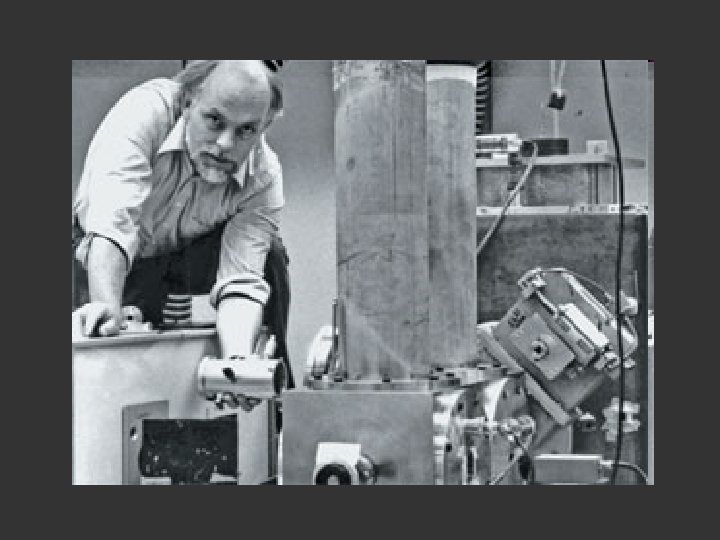
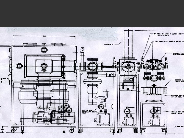
The pulses pass across the chamber at about 10 Hz …and the signal integrated perhaps 100 to a 1000 or more times The University of Sussex machine
TOF-MS Time of Flight Mass Spectrometer Pulsed Laser
TOF-MS Time of Flight Mass Spectrometer Pulsed Laser
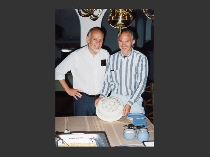
Richard Smalley, Robert Curl, and Sir Harold Kroto and their team used the AP 2 to discover C 60, or buckminsterfullerene. The skimmer captured the C 60 from the molecular stream. In 1996 they won the Nobel Prize for this work. Gift of Richard E. Smalley. Photo by Gregory Tobias. From the collections at the Chemical Heritage Foundation. CHF is a non-profit library, museum, and center for scholars that's dedicated to the history of chemistry. To learn more, visit www. chemheritage. org.
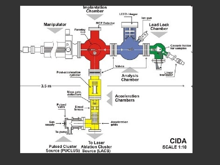
image at: www. ct. infn. it/. . . /equipmentframe. html
A high-pressure gas is expanded through a small hole into vacuum. The velocity distribution of room-temperature ammonia molecules in the container and in the supersonic beam. By using a noble gas as
Box 1. Molecular beams From the following article Taming molecular beams Sebastiaan Y. T. van de Meerakker, Hendrick L. Bethlem & Gerard Meijer Nature Physics 4, 595 - 602 (2008) doi: 10. 1038/nphys 1031 BACK TO ARTICLE A molecular beam is formed by letting a gas pass from a high-pressure container through a small orifice into an evacuated chamber, that is, by a controlled leak, as schematically shown in Fig. B 1. If the hole is much smaller than the mean free path of the gas, molecules will every now and then escape from the container through the hole without undergoing collisions. In this case, the velocity distribution as well as the distribution over the internal degrees of freedom of the molecules (rotation, vibration) in the beam is the same as that in the container. These beams are said to be effusive. Although the most probable velocity of molecules in an effusive beam originating from a room-temperature container is a few hundred metres per second, a small fraction of the molecules will have velocities below 30 m s-1. Using either curved electrostatic guides 79, 80, 81, 82 or a mechanical selector—a series of rotating blades 83—these slow molecules can be filtered out of the effusive beam and used for experiments 84. Higher fluxes of slow and internally colder molecules can be obtained when the effusive beam is extracted from a cryogenic container 85, 86. If the pressure in the container is raised or if the size of the hole is increased, the mean free path of the gas becomes smaller than the orifice. In this case, molecules escaping through the hole collide frequently, and adiabatic cooling of all degrees of freedom takes place in the expansion region. The total energy available per molecule in the gas in the container is converted into kinetic energy (directed flow), leading to supersonic beams of internally cold molecules 87. The terminal temperature in the beam is limited by the formation of clusters, which is reduced when the molecule of interest is expanded in a dilute mixture with a noble gas. When these beams are operated in a pulsed mode, pumping requirements are less severe and millimetresized orifices can be used. In these pulsed beams, densities of 1013 molecules cm-3 at translational temperatures below 1 K can be obtained. The rotational temperature in the beam is normally close to the translational temperature, whereas the vibrational degrees of freedom are known to cool considerably less well. The velocity of the beam is dictated by the mass of the carrier gas and by the temperature and pressure of the source 88. Molecules seeded in a room-temperature Kr (Xe) expansion move at a terminal velocity of about 440 m s-1 (330 m s-1). These seeded pulsed beams are ideal starting points for Stark, Zeeman and optical deceleration experiments. Rather than grabbing with fields onto the molecules, other techniques to produce slow molecular beams have been developed. In a crossed or counterpropagating beam set-up, the kinetic energy transfer in collisions 89 or reactions 90 between molecules can be exploited to produce slow or stationary molecules. Molecules can also be slowed and loaded into a magnetic trap by introducing a molecular beam into a cryogenic buffer gas 91. Mechanical methods, originally pioneered by Moon and coworkers in the 1970 s to accelerate a molecular beam 92, have been developed as well. For instance, the laboratory velocity of a molecular beam can be lowered by a nozzle that is mounted on a back-spinning rotor 93, 94 or by elastic reflection from a receding substrate 95.
Si. C target
Graphite Target o o oo o o ooooooo o o oo oo oooooo o o oooo ooo o Should produce long carbon chains
Plasma in lab Exploding Star Try to reproduce the stellar plasma in the laboratory
1. The valve opens and shuts 2. A helium pulse passes along the tube 3. The laser fires to produce a plasma of atoms (ca 10 000 o) 4. The atoms cluster as they cool 5. and are swept into the vacuum chamber