Lecture 6 1 ADVANCED PLASMA DIAGNOSTIC TECHNIQUES Fri


 • Magnetic probes • Microwave and optical")

")


- Slides: 32
Lecture 6. 1 ADVANCED PLASMA DIAGNOSTIC TECHNIQUES Fri 23 May 2008, 1 pm LT 5 Presented by Dr Ian Falconer i. falconer@physics. usyd. edu. au Room 101
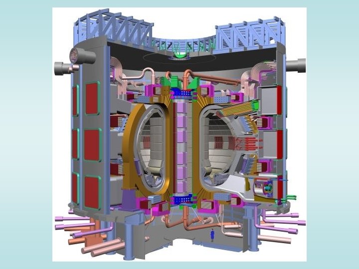
ITER
Langmuir probes
Selected ITER diagnostics Diagnostic Measures Magnetic diagnostics Plasma current, position, shape, waves. . Spectroscopic & neutral particle analyser systems Ion temperature, He & impurity density, . . Neutron diagnostics Fusion power, ion temperature profile, …. Microwave diagnostics Plasma position, shape, electron density, profile, …. . Optical/IR(infra-red) systems Electron density (Line-average & profile, electron temperature profile, …. Bolometric diagnostics Total radiated power, …. Plasma-facing components & operational diagnostics Temperature of, and particle flux to First Wall, …. . Neutral beam diagnostics Various parameters
Processing plasmas
Selected low temperature plasma diagnostics Diagnostic Measures Langmuir probes Plasma potential, electron temperature & density Magnetic diagnostics Plasma current, plasma waves, …. Spectroscopic Plasma composition, ion temperature & drift velocity, ……. Microwave diagnostics Plasma electron density, density profile, …. Laser diagnostics Density etc. of various species in plasma
PLASMA DIAGNOSTICS • Electrostatic probes (Langmuir probes) • Magnetic probes • Microwave and optical interferometry • Spectroscopic techniques • Particle analysis • Thomson scattering • Nuclear radiation detection • Laser diagnostics of processing plasmas
General characteristics of a useful plasma diagnostic • The diagnostic must not perturb the plasma – i. e. it must not change the conditions within the plasma • Plasma diagnostics generally do not give the parameter(s) directly. An understanding of the physics of the processes involved in interpreting diagnostic results is essential
Electrostatic probes (Langmuir probes)
A short length of fine wire, inserted in a plasma can give valuable information about the plasma properties at a point in the plasma. A Langmuir probe consists of such a short , thin wire inserted into the plasma: the current to/from the probe is measured as its potential is changed.
A sheath forms around the probe of thickness ~ Debye length Current to sheath For a Maxwellian velocity distribution But this applies ONLY if the potential of the probe is the same as that of the plasma. How will the current to a Langmuir probe change if we use an external voltage source to change the probe’s potential?
A “typical” Langmuir probe characteristic
Typical probe characteristic: 1 A. VS is the space or plasma potential (the potential of the plasma in the absence of a probe). There is no E. The current is due mainly to the random motion of electrons (the random motion of the ions is much slower). B. If the probe is more positive than the plasma, electrons are attracted towards the probe and all the ions are repelled. An electron sheath is formed and saturation electron current is reached. X
Typical probe characteristic: 2 C. If the probe is more negative than the plasma, electrons are repelled (but the faster ones still reach the probe) and ions are attracted. The shape of this part of the curve depends on the electron velocity distribution. For a Maxwellian distribution with Te > Ti, the slope of ln Ip plotted against Vs is D. The floating potential Vf (an insulated electrode would assume this potential) The ion flux = the electron flux so Ip = 0.
Typical probe characteristic: 3 E. All the electrons are repelled. An ion sheath is formed and saturation current is reached.
Probe surface
Magnetic probes
A voltage is induced by the changing magnetic field through this coil Integrating this voltage gives
Rogowski coil: measures plasma current Voltage induced in this toroidal coil by the magnetic field passing through area A Integrating
Voltage loop: typically used to give the voltage induced in the plasma by the Ohmic heating transformer A voltage is induced between the (open) ends of a (usually) single-turn loop adjacent to the plasma current. This voltage gives the voltage induced in the plasma by the transformer.
Measurement of induced voltage in plasma enable calculation of plasma conductivity – and hence temperature
Monitoring plasma position. Coils inside and outside the plasma, and voltage loops above and below the plasma, give the position of the plasma within the toroidal vacuum vessel. Signals from these sensors are used for feedback control of the plasma position. But only for toroidal plasmas with a circulating current – tokamaks.
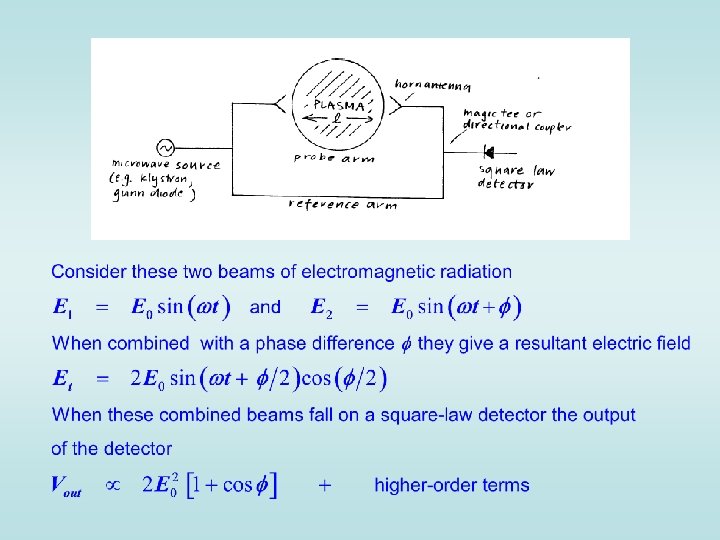
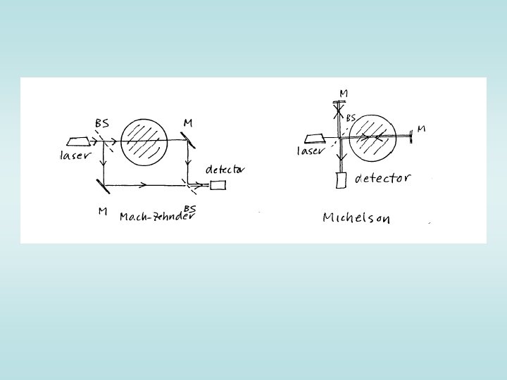
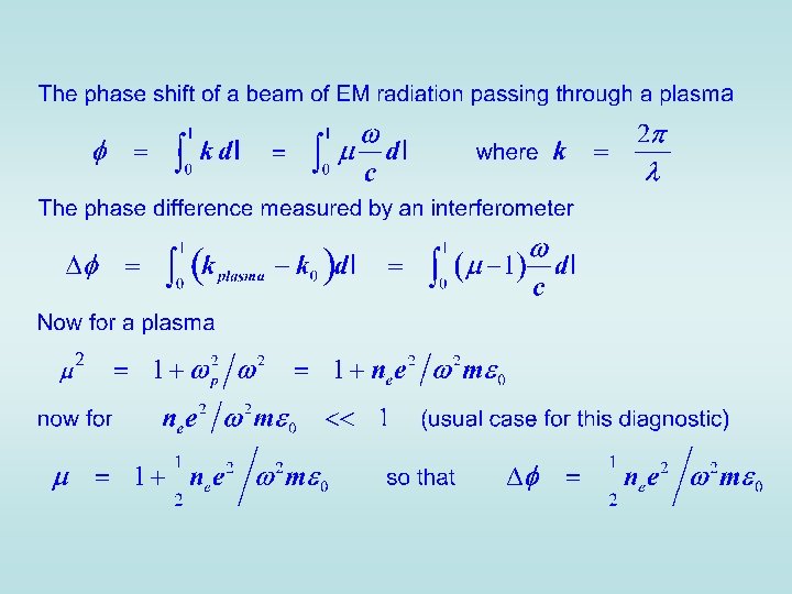
Interferometry
Thomson scattering
Thomson scattering is scattering off free electrons in the plasma. The electrons are set oscillating by the incoming laser beam, and then radiate as dipole radiators. The intensity of the scattered radiation gives the electron density, the double-Doppler broadening of the scattered radiation gives the electron temperature.
Layout of a typical Thomson scattering experiment
The ITER LIDAR Thomson scattering system
Conclusion • An array of non-perturbing diagnostic techniques has been developed to probe both fusion and “processing” plasmas • Selection of an appropriate diagnostic depends on the nature of the plasma – and the relative cost of the diagnostics available • Effective use of a diagnostic technique depends on a thorough knowledge of the physics of both the plasma and the diagnostic technique adopted