Lecture 6 1 ADVANCED PLASMA DIAGNOSTIC TECHNIQUES Presented


 § Magnetic probes § Microwave and optical")

 A short length of wire, inserted in a plasma can")


- Slides: 25
Lecture 6. 1 ADVANCED PLASMA DIAGNOSTIC TECHNIQUES Presented by Dr Ian Falconer i. falconer@physics. usyd. edu. au Room 101
LANGMUIR PROBES
Selected ITER diagnostics Diagnostic Measures Magnetic diagnostics Plasma current, position, shape, waves. . Spectroscopic & neutral particle analyser systems Ion temperature, He & impurity density, . . Neutron diagnostics Fusion power, ion temperature profile, …. Microwave diagnostics Plasma position, shape, electron density, profile, …. . Optical/IR(infra-red) systems Electron density (Line-average & profile, electron temperature profile, …. Bolometric diagnostics Total radiated power, …. Plasma-facing components & operational diagnostics Temperature of, and particle flux to First Wall, …. . Neutral beam diagnostics Various parameters
Selected low temperature plasma diagnostics Diagnostic Measures Langmuir probes Plasma potential, electron temperature & density Magnetic diagnostics Plasma current, plasma waves, …. Spectroscopic Plasma composition, ion temperature & drift velocity, ……. Microwave diagnostics Plasma electron density, density profile, …. . Mass / energy analyser Identifie sspecies of ions, and measures their charge state and energy Laser diagnostics Density etc. of various species in the plasma: density, distribution, and even in the plasma.
PLASMA DIAGNOSTICS § Electrostatic probes (Langmuir probes) § Magnetic probes § Microwave and optical interferometry § Spectroscopic techniques § Particle analysis § Thomson scattering § Nuclear radiation detection § Laser diagnostics of processing plasmas
General characteristics of a useful plasma diagnostic • The diagnostic must not perturb the plasma – i. e. it must not change the conditions within the plasma • Plasma diagnostics generally do not give the parameters) directly. An understanding of the physics of the processes involved in interpreting diagnostic results is essential
Electrostatic probes (Langmuir probes) A short length of wire, inserted in a plasma can give valuable information of the plasma properties at a point in the plasma. A Langmuir probe consists of such a short , thin wire inserted into the plasma: the current to/from the probe is measured as its potential is changed.
A sheath forms around the probe of thickness ~ Debye length Current to sheath For a Maxwellian velocity distribution But this applies ONLY if the potential of the probe is the same as that of the plasma. How will the current to a Langmuir probe change if we use an external voltage source to change the probe’s potential?
A “typical” Langmuir probe characteristic
Typical probe characteristic: 1 A. VS is the space or plasma potential (the potential of the plasma in the absence of a probe). There is no E. The current is due mainly to the random motion of electrons (the random motion of the ions is much slower). of y t i n i c in vi e b o r p the o b t r t u t n r n pe curre a h c g i B H and ason potential A e r s t s i n poi or th f plasma c are F. a i o plasm rements aracterist n of u h o s i c t a a e e m rob min om p nd deter robe r f Vp ble, a ity from p ore so. a i l e r un dens nt even m n o r t elec tion curre a satur B. If the probe is more positive than the plasma, electrons are attracted towards the probe and all the ions are repelled. An electron sheath is formed and saturation electron current is reached. X
Typical probe characteristic: 2 C. If the probe is more negative than the plasma, electrons are repelled (but the faster ones still reach the probe) and ions are attracted. The shape of this part of the curve depends on the electron velocity distribution. For a Maxwellian distribution with Te > Ti, the slope of ln Ip plotted against Vs is D. The floating potential VF (an insulated electrode would assume this potential) The ion flux = the electron flux so Ip = 0. t no be that is o r p a to it will flow ircuit until c l a Electrons n r te x to an e connected l is potentia th s e h c a e r
Typical probe characteristic: 3 E. All the electrons are repelled. An ion sheath is formed and saturation current is reached.
Sheath and presheath There is a region adjacent to the sheath – the presheath – where the plasma is imperfectly shielded from the probe potential. In region A ions are accelerated through the resulting small potential to reach a velocity comparable with the electrons’ thermal velocity. This must be taken into account when using this region of the probe’s characteristic to estimate ion density in the plasma. Probe surface
Magnetic probes A voltage is induced by the changing magnetic field through this coil Integrating this voltage gives
Rogowski coil: measures plasma current Voltage induced in this toroidal coil by the magnetic field passing through area A Integrating
Voltage loop: typically used to give the voltage induced in the plasma by the Ohmic heating transformer A voltage is induced between the (open) ends of a (usually) single-turn loop adjacent to the plasma current. This voltage gives the voltage induced in the plasma by the transformer.
Measurement of induced voltage in plasma enable calculation of plasma conductivity – and hence temperature
Monitoring plasma position. Coils inside and outside the plasma in a tokamak, and voltage loops above and below the plasma, give the position of the plasma within the toroidal vacuum vessel. Signals from these sensors are used for feedback control of the plasma position. (But only for toroidal plasmas with a circulating current – tokamaks. )
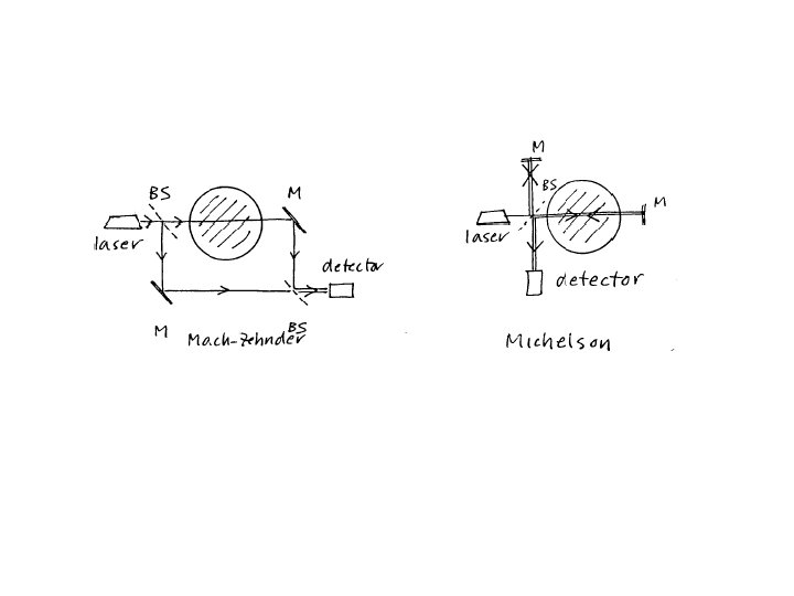
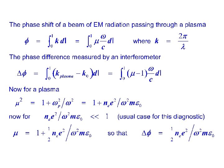
Interferometry
Thomson scattering is scattering off free electrons in the plasma. The electrons are set oscillating by the incoming laser beam, and then radiate as dipole radiators. The intensity of the scattered radiation gives the electron density, the double-Doppler broadening of the scattered radiation gives the electron temperature. The Thomson scattering cross-section for individual electrons is minute: 6. 65 x 10 -29 m 2. Thus for a plasma of density ~ 1022 m-3 only ~ 6. 65 x 10 -9 of the incident radiation will be scattered from a scattering volume of 1 cm 3 and only a small fraction of this will enter the spectrometer/detection system. (The electrons are dipole radiators. ) Thus a powerful laser is required to obtain sufficient photons to detect the scattered radiation, and stray light from the laser and other sources presents difficulties in observing the scattered radiation. (A 0. 05 joule pulse from a frequency-doubled Nd: YAG laser at 532 nm - a powerful laser pulse – contains ~1017 photons, so that only ~109 photons will be scattered from this volume, and many fewer than 10% of these will enter the detection system. )
Layout of a typical Thomson scattering experiment
The ITER LIDAR Thomson scattering system Here the spectrum of the laser radiation scattered back along the laser beam is recorded as a function of time. The width of the spectrum gives the electron temperature at a point within the plasma, and time of arrival of the scattered radiation gives the position at which the temperature was measured. As the Doppler shift for radiation that is backscattered through a very large angle is small this technique is only feasible for very hot plasmas. It is best suited fas a diagnostic for a large plasma, so that the incident laser pulse and the weak scattered beam are well-separated in time.
Conclusion • An array of non-perturbing diagnostic techniques has been developed to probe both fusion and “processing” plasmas • Selection of an appropriate diagnostic depends on the nature of the plasma – and the relative cost of the diagnostics available • Effective use of a diagnostic technique depends on a thorough knowledge of the physics of both the plasma and the diagnostic technique adopted