Immersive Visualization and Analysis of Ground Penetrating Radar


- Slides: 84

Immersive Visualization and Analysis of Ground Penetrating Radar Data By Matthew Sgambati 1 of 84

Committee Dr. Daniel Coming Dr. Frederick C. Harris, Jr. Dr. Nicholas Lancaster 2 of 84

Overview Ø Background Ø The Project Ø Software Specification and Design Process Ø Implementation Ø Results Ø Conclusion Ø Future Work 3 of 84

Background Ø Background Sand Dunes Ø Ground Penetrating Radar and Brunton Compass Ø Volume Rendering Ø Virtual Reality Ø Toirt-Samhlaigh Ø Ø Ø Ø The Project Software Specification and Design Process Implementation Results Conclusion Future Work Sand Dunes 4 of 84

Background Ø Background Sand Dunes Ø Ground Penetrating Radar and Brunton Compass Ø Volume Rendering Ø Virtual Reality Ø Toirt-Samhlaigh Ø Ø Ø Ø The Project Software Specification and Design Process Implementation Results Conclusion Future Work Sand Dunes 5 of 84

Background Ø Background Sand Dunes Ø Ground Penetrating Radar and Brunton Compass Ø Volume Rendering Ø Virtual Reality Ø Toirt-Samhlaigh Ø Ø Ø Ø The Project Software Specification and Design Process Implementation Results Conclusion Future Work Sand Dunes 6 of 84

Ø Background Sand Dunes Background § Sand Dunes Ø Ground Penetrating Radar and Brunton Compass Ø Volume Rendering Ø Virtual Reality Ø Toirt-Samhlaigh Ø Ø Ø Ø The Project Software Specification and Design Process Implementation Results Conclusion Future Work Shapes § § § § Crescentic Linear Star Dome Parabolic Transverse Reversing 7 of 84

Ø Background Sand Dunes Background § Sand Dunes Ø Ground Penetrating Radar and Brunton Compass Ø Volume Rendering Ø Virtual Reality Ø Toirt-Samhlaigh Ø Ø Ø Ø The Project Software Specification and Design Process Implementation Results Conclusion Future Work Types § § Sub-aqueous Lithified Coastal Desert 8 of 84

Ø Background Sand Dunes Background § Sand Dunes Ø Ground Penetrating Radar and Brunton Compass Ø Volume Rendering Ø Virtual Reality Ø Toirt-Samhlaigh Ø Ø Ø Ø The Project Software Specification and Design Process Implementation Results Conclusion Future Work Forms § § § Simple Compound Complex 9 of 84

Background Ø Sand Dunes Background Sand Dunes Ø Ground Penetrating Radar and Brunton Compass Ø Volume Rendering Ø Virtual Reality Ø Toirt-Samhlaigh Ø Ø Ø Ø The Project Software Specification and Design Process Implementation Results Conclusion Future Work Dune 7 in the Namib desert 10 of 84

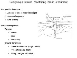
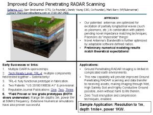
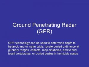
Background Ø Background Sand Dunes Ø Ground Penetrating Radar and Brunton Compass Ø Volume Rendering Ø Virtual Reality Ø Toirt-Samhlaigh Ø Ø Ø Ø The Project Software Specification and Design Process Implementation Results Conclusion Future Work Ground Penetrating Radar 11 of 84

Background Ø Background Sand Dunes Ø Ground Penetrating Radar and Brunton Compass Ø Volume Rendering Ø Virtual Reality Ø Toirt-Samhlaigh Ø Ø Ø Ø The Project Software Specification and Design Process Implementation Results Conclusion Future Work Ground Penetrating Radar 12 of 84

Background Ø Background Sand Dunes Ø Ground Penetrating Radar and Brunton Compass Ø Volume Rendering Ø Virtual Reality Ø Toirt-Samhlaigh Ø Ø Ø Ø The Project Software Specification and Design Process Implementation Results Conclusion Future Work Ground Penetrating Radar 13 of 84

Background Ø Background Sand Dunes Ø Ground Penetrating Radar and Brunton Compass Ø Volume Rendering Ø Virtual Reality Ø Toirt-Samhlaigh Ø Ø Ø Ø The Project Software Specification and Design Process Implementation Results Conclusion Future Work Brunton Compass 14 of 84

Background Ø Background Sand Dunes Ø Ground Penetrating Radar and Brunton Compass Ø Volume Rendering Ø Virtual Reality Ø Toirt-Samhlaigh Ø Ø Ø Ø The Project Software Specification and Design Process Implementation Results Conclusion Future Work Brunton Compass 15 of 84

Background Ø Background Sand Dunes Ø Ground Penetrating Radar and Brunton Compass Ø Volume Rendering Ø Virtual Reality Ø Toirt-Samhlaigh Ø Ø Ø Ø The Project Software Specification and Design Process Implementation Results Conclusion Future Work Brunton Compass 16 of 84

Ø Background Volume Rendering Background § Sand Dunes Ø Ground Penetrating Radar and Brunton Compass Ø Volume Rendering Ø Virtual Reality Ø Toirt-Samhlaigh Ø Ø Ø Ø The Project Software Specification and Design Process Implementation Results Conclusion Future Work 17 of 84 Display of data sampled in three dimensions

Background Ø Background Sand Dunes Ø Ground Penetrating Radar and Brunton Compass Ø Volume Rendering Ø Virtual Reality Ø Toirt-Samhlaigh Ø Ø Ø Ø The Project Software Specification and Design Process Implementation Results Conclusion Future Work Volume Rendering 18 of 84

Background Ø Background Sand Dunes Ø Ground Penetrating Radar and Brunton Compass Ø Volume Rendering Ø Virtual Reality Ø Toirt-Samhlaigh Ø Ø Ø Ø The Project Software Specification and Design Process Implementation Results Conclusion Future Work Volume Rendering 19 of 84

Ø Background Volume Rendering Background § Sand Dunes Ø Ground Penetrating Radar and Brunton Compass Ø Volume Rendering Ø Virtual Reality Ø Toirt-Samhlaigh Ø Ø Ø Ø The Project Software Specification and Design Process Implementation Results Conclusion Future Work Methodologies § § § Indirect Direct Algorithm categories § § § Object-order Image-order Hybrid 20 of 84

Ø Background Indirect Background § Sand Dunes Ø Ground Penetrating Radar and Brunton Compass Ø Volume Rendering Ø Virtual Reality Ø Toirt-Samhlaigh Ø Ø Ø Ø The Project Software Specification and Design Process Implementation Results Conclusion Future Work Iso-surfaces 21 of 84

Ø Background Indirect Background § Sand Dunes Ø Ground Penetrating Radar and Brunton Compass Ø Volume Rendering Ø Virtual Reality Ø Toirt-Samhlaigh Ø Ø Ø Ø The Project Software Specification and Design Process Implementation Results Conclusion Future Work Assumptions § § § 22 of 84 Iso-surfaces exist Rendered within a reasonable degree of accuracy Complexity is an issue

Ø Background Direct Background § Sand Dunes Ø Ground Penetrating Radar and Brunton Compass Ø Volume Rendering Ø Virtual Reality Ø Toirt-Samhlaigh Ø Ø Ø Ø The Project Software Specification and Design Process Implementation Results Conclusion Future Work Requirement § § 23 of 84 Every sample point is mapped to an opacity and color Techniques § § § Ray Casting Splatting Shear-Warp Texture Mapping Hardware Accelerated

Background Ø Background Sand Dunes Ø Ground Penetrating Radar and Brunton Compass Ø Volume Rendering Ø Virtual Reality Ø Toirt-Samhlaigh Ø Ø Ø Ø The Project Software Specification and Design Process Implementation Results Conclusion Future Work Ray Casting Image-order algorithm Produces some of the highest quality images § Very computationally expensive § § 24 of 84

Background Ø Background Sand Dunes Ø Ground Penetrating Radar and Brunton Compass Ø Volume Rendering Ø Virtual Reality Ø Toirt-Samhlaigh Ø Ø Ø Ø The Project Software Specification and Design Process Implementation Results Conclusion Future Work Ray Casting 25 of 84

Background Ø Background Sand Dunes Ø Ground Penetrating Radar and Brunton Compass Ø Volume Rendering Ø Virtual Reality Ø Toirt-Samhlaigh Ø Ø Ø Ø The Project Software Specification and Design Process Implementation Results Conclusion Future Work Splatting 26 of 84 Object-order algorithm Less computationally expensive than Ray Casting § Throw paint balls onto a surface to obtain an image § §

Ø Background Splatting Background § Sand Dunes Ø Ground Penetrating Radar and Brunton Compass Ø Volume Rendering Ø Virtual Reality Ø Toirt-Samhlaigh Ø Ø Ø Ø The Project Software Specification and Design Process Implementation Results Conclusion Future Work 27 of 84 Maps every voxel to the viewing plane § Footprint § § Speed § § Reconstruction Kernel Precompute footprints Issue § Reconstruction Kernel selection § Too larger results in a blurry image

Background Ø Background Sand Dunes Ø Ground Penetrating Radar and Brunton Compass Ø Volume Rendering Ø Virtual Reality Ø Toirt-Samhlaigh Ø Ø Ø Ø The Project Software Specification and Design Process Implementation Results Conclusion Future Work Splatting 28 of 84

Background Ø Background Sand Dunes Ø Ground Penetrating Radar and Brunton Compass Ø Volume Rendering Ø Virtual Reality Ø Toirt-Samhlaigh Ø Ø Ø Ø The Project Software Specification and Design Process Implementation Results Conclusion Future Work Shear-Warp § § 29 of 84 Hybrid algorithm Fastest purely software-based algorithm

Ø Background Shear-Warp Background § Sand Dunes Ø Ground Penetrating Radar and Brunton Compass Ø Volume Rendering Ø Virtual Reality Ø Toirt-Samhlaigh Ø Ø Ø Ø The Project Software Specification and Design Process Implementation Results Conclusion Future Work Sheared object space 30 of 84

Background Ø Background Sand Dunes Ø Ground Penetrating Radar and Brunton Compass Ø Volume Rendering Ø Virtual Reality Ø Toirt-Samhlaigh Ø Ø Ø Ø The Project Software Specification and Design Process Implementation Results Conclusion Future Work Shear-Warp 31 of 84

Ø Background Shear-Warp Background § Sand Dunes Ø Ground Penetrating Radar and Brunton Compass Ø Volume Rendering Ø Virtual Reality Ø Toirt-Samhlaigh Ø Ø Ø Ø The Project Software Specification and Design Process Implementation Results Conclusion Future Work Speed § § 32 of 84 Run-length encoding Issues Run-length encoding § § One for each axis, 3 x memory consumption § Interpolation is per slice § § Aliasing Staircasing

Ø Background Texture Mapping Background § Sand Dunes Ø Ground Penetrating Radar and Brunton Compass Ø Volume Rendering Ø Virtual Reality Ø Toirt-Samhlaigh Ø Ø Ø Ø The Project Software Specification and Design Process Implementation Results Conclusion Future Work Uses Graphics Hardware § § § 33 of 84 Texture Mapping Interpolation Types § § 2 D-texture mapping 3 D-texture mapping

Ø Background 2 D-Texture Mapping Background § Sand Dunes Ø Ground Penetrating Radar and Brunton Compass Ø Volume Rendering Ø Virtual Reality Ø Toirt-Samhlaigh Ø Ø Ø Ø The Project Software Specification and Design Process Implementation Results Conclusion Future Work 34 of 84 Splits data into axis-aligned slices § Composited in back-to-front order

Ø Background 2 D-Texture Mapping Background § Sand Dunes Ø Ground Penetrating Radar and Brunton Compass Ø Volume Rendering Ø Virtual Reality Ø Toirt-Samhlaigh Ø Ø Ø Ø The Project Software Specification and Design Process Implementation Results Conclusion Future Work Advantages § § § 35 of 84 Simplicity Takes advantage of graphics hardware (Bilinear interpolation) Disadvantages § § § Slices created for each axis, 3 x memory consumption Flickering Aliasing occurs when magnified

Background Ø Background Sand Dunes Ø Ground Penetrating Radar and Brunton Compass Ø Volume Rendering Ø Virtual Reality Ø Toirt-Samhlaigh Ø Ø Ø Ø The Project Software Specification and Design Process Implementation Results Conclusion Future Work 3 D-Texture Mapping § § 36 of 84 Stores data as a 3 D-texture Creates viewport aligned slices

Ø Background 3 D-Texture Mapping Background § Sand Dunes Ø Ground Penetrating Radar and Brunton Compass Ø Volume Rendering Ø Virtual Reality Ø Toirt-Samhlaigh Ø Ø Ø Ø The Project Software Specification and Design Process Implementation Results Conclusion Future Work 37 of 84 Advantages § § Overcomes disadvantages of 2 D-texture mapping Takes advantage of graphics hardware (Trilinear interpolation)

Ø Background 3 D-Texture Mapping Background § Sand Dunes Ø Ground Penetrating Radar and Brunton Compass Ø Volume Rendering Ø Virtual Reality Ø Toirt-Samhlaigh Ø Ø Ø Ø The Project Software Specification and Design Process Implementation Results Conclusion Future Work 38 of 84 Disadvantages § Bricking mechanism required for large data sets § Limited by bandwidth between system memory and graphics hardware § Brick size § Too large wont fit into graphics hardware’s memory cache § Too small increases memory footprint and number of intersection tests

Ø Background Hardware Accelerated Background § Sand Dunes Ø Ground Penetrating Radar and Brunton Compass Ø Volume Rendering Ø Virtual Reality Ø Toirt-Samhlaigh Ø Ø Ø Ø The Project Software Specification and Design Process Implementation Results Conclusion Future Work 39 of 84 Uses Programmable Pipeline instead of the Fixed Functionality Pipeline

Ø Background Virtual Reality Background § Sand Dunes Ø Ground Penetrating Radar and Brunton Compass Ø Volume Rendering Ø Virtual Reality Ø Toirt-Samhlaigh Ø Ø Ø Ø The Project Software Specification and Design Process Implementation Results Conclusion Future Work Notion of mental immersion through feedback § § § 40 of 84 Visual Haptic Olfactory Auditory Depth Cues § § § Monoscopic Stereoscopic Motion

Ø Background Virtual Reality Background § Sand Dunes Ø Ground Penetrating Radar and Brunton Compass Ø Volume Rendering Ø Virtual Reality Ø Toirt-Samhlaigh Ø Ø Ø Ø The Project Software Specification and Design Process Implementation Results Conclusion Future Work Stereo Vision § § § Stereoscopic Displays § § § Active Passive Fishtank Head Mounted Display Projection-based Input Devices Toolkits 41 of 84

Ø Background Depth Cues Background § Sand Dunes Ø Ground Penetrating Radar and Brunton Compass Ø Volume Rendering Ø Virtual Reality Ø Toirt-Samhlaigh Ø Ø Ø Ø The Project Software Specification and Design Process Implementation Results Conclusion Future Work 42 of 84 Monoscopic § § Provide information from only one eye Information § § Interposition Size Linear perspective Motion parallax

Ø Background Depth Cues Background § Sand Dunes Ø Ground Penetrating Radar and Brunton Compass Ø Volume Rendering Ø Virtual Reality Ø Toirt-Samhlaigh Ø Ø Ø Ø The Project Software Specification and Design Process Implementation Results Conclusion Future Work 43 of 84 Stereoscopic Provide information from two eyes § Images are different perspectives of the same location § § Motion § § Provides spatial information Obtained from the parallax between objects in the image Same as motion parallax Not always present

Ø Background Stereo Vision Background § Sand Dunes Ø Ground Penetrating Radar and Brunton Compass Ø Volume Rendering Ø Virtual Reality Ø Toirt-Samhlaigh Ø Ø Ø Ø The Project Software Specification and Design Process Implementation Results Conclusion Future Work 44 of 84 Active 1 Projector with 120 Hz refresh rate (60 Hz each eye) § Synchronized signals between projector and glasses §

Ø Background Stereo Vision Background § Sand Dunes Ø Ground Penetrating Radar and Brunton Compass Ø Volume Rendering Ø Virtual Reality Ø Toirt-Samhlaigh Ø Ø Ø Ø The Project Software Specification and Design Process Implementation Results Conclusion Future Work 45 of 84 Passive § § 2 Projectors (60 Hz refresh rate) Polarized filters

Ø Background Stereoscopic Displays Background § Sand Dunes Ø Ground Penetrating Radar and Brunton Compass Ø Volume Rendering Ø Virtual Reality Ø Toirt-Samhlaigh Ø Ø Ø Ø The Project Software Specification and Design Process Implementation Results Conclusion Future Work Types § § § Fishtank Head Mounted Display Projection-based 46 of 84

Background Ø Background Sand Dunes Ø Ground Penetrating Radar and Brunton Compass Ø Volume Rendering Ø Virtual Reality Ø Toirt-Samhlaigh Ø Ø Ø Ø The Project Software Specification and Design Process Implementation Results Conclusion Future Work Stereoscopic Displays 47 of 84

Background Ø Background Sand Dunes Ø Ground Penetrating Radar and Brunton Compass Ø Volume Rendering Ø Virtual Reality Ø Toirt-Samhlaigh Ø Ø Ø Ø The Project Software Specification and Design Process Implementation Results Conclusion Future Work Stereoscopic Displays 48 of 84

Background Ø Background Sand Dunes Ø Ground Penetrating Radar and Brunton Compass Ø Volume Rendering Ø Virtual Reality Ø Toirt-Samhlaigh Ø Ø Ø Ø The Project Software Specification and Design Process Implementation Results Conclusion Future Work Stereoscopic Displays 49 of 84

Background Ø Background Sand Dunes Ø Ground Penetrating Radar and Brunton Compass Ø Volume Rendering Ø Virtual Reality Ø Toirt-Samhlaigh Ø Ø Ø Ø The Project Software Specification and Design Process Implementation Results Conclusion Future Work Input Devices 50 of 84

Ø Background Toolkits Background § Sand Dunes Ø Ground Penetrating Radar and Brunton Compass Ø Volume Rendering Ø Virtual Reality Ø Toirt-Samhlaigh Ø Ø Ø Ø The Project Software Specification and Design Process Implementation Results Conclusion Future Work Designed to help users deal with VR systems § § 51 of 84 Specialized hardware Specialized devices Unique environments Examples § § Free. VR VR Juggler Virtual reality user interface (Vrui) Hydra

Ø Background Vrui Background § VR development toolkit Sand Dunes Ø Ground Penetrating Radar and Brunton Compass Ø Volume Rendering Ø Virtual Reality Ø Toirt-Samhlaigh Ø Ø Ø Ø The Project Software Specification and Design Process Implementation Results Conclusion Future Work 52 of 84 written by Oliver Kreylos § Goal is to shield developer from a particular configuration of a VR environment § § § Display abstraction Distribution abstraction Input abstraction

Ø Background Toirt-Samhlaigh Background § Sand Dunes Ø Ground Penetrating Radar and Brunton Compass Ø Volume Rendering Ø Virtual Reality Ø Toirt-Samhlaigh Ø Ø Ø Ø The Project Software Specification and Design Process Implementation Results Conclusion Future Work Volume rendering library § § Patrick O’Leary 3 D-texture mapping, hardware accelerated DVR type of algorithm § § 53 of 84 Slice-based rendering Heavily integrated with Vrui

Ø Background Toirt-Samhlaigh Background § Sand Dunes Ø Ground Penetrating Radar and Brunton Compass Ø Volume Rendering Ø Virtual Reality Ø Toirt-Samhlaigh Ø Ø Ø Ø The Project Software Specification and Design Process Implementation Results Conclusion Future Work Provides many features § § § § 54 of 84 Transfer functions Directional lighting Volume manipulation Color maps Tools, such as clipping plane tool Modifiable slice factor Load several data types

The Project Ø Ø Ø Ø Background The Project Software Specification and Design Process Implementation Results Conclusion Future Work 55 of 84 Create a program capable of visualizing GPR data in an IVE and create tools to assist in the analysis of the GPR data This was done by taking Toirt. Samhlaigh and performing enhancements and expansions to the library

Software Specification and Design Process Ø Ø Ø Background The Project Software Specification and Design Process Requirements Ø Use Cases Ø System Overview Ø Iterative Design Process Ø Ø Ø Implementation Results Conclusion Future Work Software Specification § Requirements § § Functional Nonfunctional 56 of 84

Software Specification and Design Process Ø Ø Ø Background The Project Software Specification and Design Process Requirements Ø Use Cases Ø System Overview Ø Iterative Design Process Ø Ø Ø Implementation Results Conclusion Future Work Requirements § Functional § § § 57 of 84 The program shall be able to load GPR data in SEG Y revision 1 format. The program shall allow the user to turn the data visualization on and off. The program shall allow the user to change the orientation and position of the data. The program shall allow the user to take dip and strike measurements. The program shall allow the user to take distance and angle measurements.

Software Specification and Design Process Ø Ø Ø Background The Project Software Specification and Design Process Requirements Ø Use Cases Ø System Overview Ø Iterative Design Process Ø Ø Ø Implementation Results Conclusion Future Work Requirements § Nonfunctional § § § 58 of 84 The program shall maintain interactive frame rates. The program shall written in C/C++. The program shall use a hardware accelerated, texture mapping DVR algorithm for its rendering. The program shall use VRUI and Toirt. Samhlaigh for its prototype application. The program's rendering algorithm shall use Open. GL. The program shall be implemented on the Linux platform.

Software Specification and Design Process Ø Ø Ø Background The Project Software Specification and Design Process Requirements Ø Use Cases Ø System Overview Ø Iterative Design Process Ø Ø Ø Implementation Results Conclusion Future Work Use Cases 59 of 84

Software Specification and Design Process Ø Ø Ø Background The Project Software Specification and Design Process Requirements Ø Use Cases Ø System Overview Ø Iterative Design Process Ø Ø Ø Implementation Results Conclusion Future Work System Overview 60 of 84

Software Specification and Design Process Ø Ø Ø Background The Project Software Specification and Design Process Requirements Ø Use Cases Ø System Overview Ø Iterative Design Process Ø Ø Ø Implementation Results Conclusion Future Work Toirt-Samhlaigh 61 of 84

Software Specification and Design Process Ø Ø Ø Background The Project Software Specification and Design Process Requirements Ø Use Cases Ø System Overview Ø Iterative Design Process Ø Ø Ø Implementation Results Conclusion Future Work Iterative Design Process 62 of 84 § Conducted with a researcher at DRI § § Valuable feedback Valuable learning experience

Implementation Ø Ø Ø Ø Background The Project Software Specification and Design Process Implementation Results Conclusion Future Work § § § 63 of 84 SEG Y file loader Toirt-Samhlaigh tools tested Modified Slicing Tool § § Handle scaling of GPR data Double as a clipping tool Added Topographic correction to SEG Y file loader § Surface Visualization § § Transparency modifiable

Implementation Ø Ø Ø Ø Background The Project Software Specification and Design Process Implementation Results Conclusion Future Work § Two tools created § § 64 of 84 Distance Measurement Tool Brunton Compass Tool GUIs were created as needed Save/Load Functionality

Implementation Ø Ø Ø Ø Background The Project Software Specification and Design Process Implementation Results Conclusion Future Work Topographic Correction 65 of 84 § Store values read in from a file into a 2 D grid structure § x-coordinate, y-coordinate, elevation § Samples taken at regular intervals, plus at the peaks § Performed linear interpolation

Implementation Ø Ø Ø Ø Background The Project Software Specification and Design Process Implementation Results Conclusion Future Work Topographic Correction 66 of 84

Implementation Ø Ø Ø Ø Background The Project Software Specification and Design Process Implementation Results Conclusion Future Work Topographic Correction 67 of 84

Implementation Ø Ø Ø Ø Background The Project Software Specification and Design Process Implementation Results Conclusion Future Work Surface Visualization 68 of 84

Implementation Ø Ø Ø Ø Background The Project Software Specification and Design Process Implementation Results Conclusion Future Work Distance Measurement Tool 69 of 84

Implementation Ø Ø Ø Ø Background The Project Software Specification and Design Process Implementation Results Conclusion Future Work Brunton Compass Tool 70 of 84

Implementation Ø Ø Ø Ø Background The Project Software Specification and Design Process Implementation Results Conclusion Future Work Brunton Compass Tool 71 of 84

Results Ø Ø Ø Ø Background The Project Software Specification and Design Process Implementation Results Conclusion Future Work § Videos § § § § 72 of 84 Volume orientation and position Directional lighting Color Maps Slice Tool 1 D Transfer Function Surface Visualization Distance Measurement Tool Brunton Compass Tool

Results Ø Ø Ø Ø Background The Project Software Specification and Design Process Implementation Results Conclusion Future Work Volume Orientation and Position 73 of 84

Results Ø Ø Ø Ø Background The Project Software Specification and Design Process Implementation Results Conclusion Future Work Directional Lighting 74 of 84

Results Ø Ø Ø Ø Background The Project Software Specification and Design Process Implementation Results Conclusion Future Work Color Maps 75 of 84

Results Ø Ø Ø Ø Background The Project Software Specification and Design Process Implementation Results Conclusion Future Work Slice Tool 76 of 84

Results Ø Ø Ø Ø Background The Project Software Specification and Design Process Implementation Results Conclusion Future Work 1 D Transfer Function 77 of 84

Results Ø Ø Ø Ø Background The Project Software Specification and Design Process Implementation Results Conclusion Future Work Surface Visualization 78 of 84

Results Ø Ø Ø Ø Background The Project Software Specification and Design Process Implementation Results Conclusion Future Work Distance Measurement Tool 79 of 84

Results Ø Ø Ø Ø Background The Project Software Specification and Design Process Implementation Results Conclusion Future Work Brunton Compass Tool 80 of 84

Conclusion Ø Ø Ø Ø Background The Project Software Specification and Design Process Implementation Results Conclusion Future Work § Background § The Project § Software Specification and Design Process § Implementation § Results § Conclusion § Future Work 81 of 84

Future Work Ø Ø Ø Ø Background The Project Software Specification and Design Process Implementation Results Conclusion Future Work § Improve User Friendliness § § File selection menu Change the scale of the data Change the loaded data set Tools § § 82 of 84 Custom shaped viewing tool Layer peeling tool Auto subsurface generating tool Load more GPR file formats and different types of data

Future Work Ø Ø Ø Ø Background The Project Software Specification and Design Process Implementation Results Conclusion Future Work 83 of 84 Have more than one volume loaded at a time § Perform automatic or semiautomatic segmentation of the data into layers § Clipping Plane issue § Replace Toirt-Samhlaigh § § Implements newer DVR algorithms Takes better advantage of graphics hardware Not integrated with a VR toolkit

Questions Thank you for coming Demo at 2: 00 p. m. 84 of 84
 Civil engineering applications of ground penetrating radar
 Saltenna
 Portal quest fantasy
 Moving target indicator radar
 Mti versus pulse doppler radar
 Ppgbqa
 Non penetrating glaucoma surgery
 Tamara munzner data visualization
 Signal analysis and visualization
 Radar range equation snr
 Radar system analysis and design using matlab
 Market basket analysis visualization
 Visualization analysis & design
 Before and after data visualization
 A nested model for visualization design and validation
 Modeling and visualization of leaf venation patterns
 Radar stands for radio detection and
 Search and rescue radar transponder
 Alignment test
 Radar and sonar technician career cluster
 Prims algorithm visualization
 Ocean data visualization
 Vli demo tool
 Red black tree visualization
 Horspool algorithm visualization
 Spatial visualization training
 Robot simulation visualization
 Ist scientific
 Visualization pipeline
 Google visualization api query language
 2d array visualization
 Weka visualization
 Shneiderman's visualization mantra
 Data visualization rules of thumb
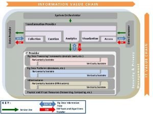
 Value chain visualization
 Huffman coding visualization
 Heap visualization
 Binomial heap merge visualization
 Gephi alternative
 Ekahau visualization tags
 Dynamic network visualization
 Visualize an acre
 Bad graphs
 Task abstraction definition
 Adaptive huffman coding in data compression
 Benchmarking visualization
 Flask data visualization
 Bgp route visualization
 Visualization reading strategy
 Inorder traversal visualization
 Information visualization ppt
 Heapsort visualization
 Quickselect visualization
 Doubly linked list visualization
 Embedded systems visualization
 Cognos mobile app
 Huffman encoding visualizer
 Suffix array python
 Data visualization meetup
 Abela's chart type hierarchy
 Sketch data visualization
 Bellman ford visualization
 Visualization in user interface design
 Traverse huffman tree
 Alpha beta pruning visualization
 Music data visualization
 Is visualization a sin
 Extendible hashing visualization
 Raft protocol visualization
 Translate
 Node-link
 Voyager data visualization
 Data visualization lecture
 Introduction to information visualization
 Discoveryben
 Huffman tree visualization
 Network flow visualization tool
 Splay tree visualization
 Traffic data visualization
 Gdaymath
 Azure msp playbook
 Taintchain
 Purdue spatial visualization test answer key
 Treap visualization
 Nondeterministic pushdown automata
