Designing a Ground Penetrating Radar Experiment You need


- Slides: 7
Designing a Ground Penetrating Radar Experiment You need to determine: 1. Amount of time to record the signal 2. Antenna frequency 3. Line spacing While thinking about: Targets: • Depth • Size • Geometry Ground Conditions • Surface conditions (rough? wet? ) • Type of material (RDP) • Likely changes with depth
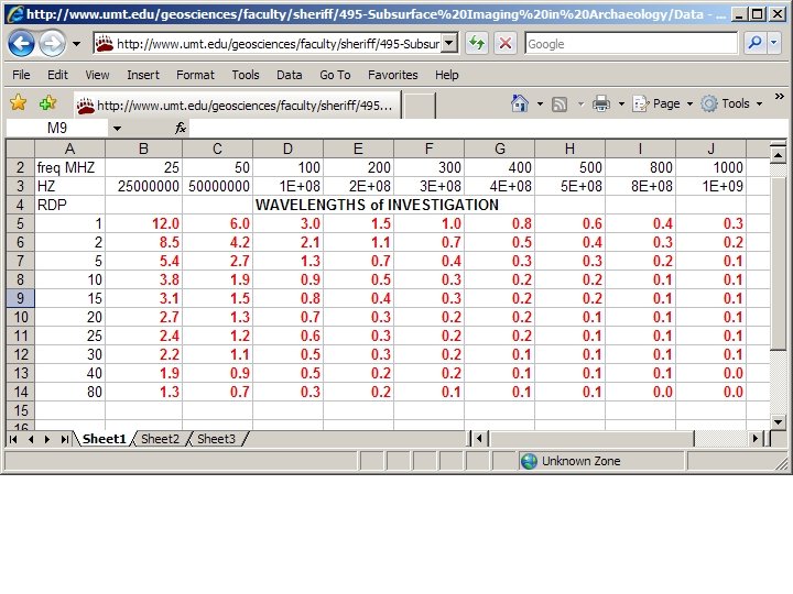
Time = distance/velocity We need time for the radar wave to descend to a reflector and return to the surface (two-way travel time). From the chart you can see that the amount of recording time is dependent on target depth and the underlying material. For example: 1. A one meter deep target in dry sand requires t = 2 * 100 cm/15 cm/s = ~14 ns 2. The same target in saturated sand requires t = 2 * 100 cm/6 cm/s = ~34 ns
Wavelength = velocity / frequency Unfortunately, Earth is an efficient absorber of high frequency electromagnetic waves. Higher frequencies yield greater resolution but less depth penetration. Assuming ‘normal’ geologic materials: For depths 0. 3 < d < 2 meters antennas of 400 -500 MHz usually work well For depths 1 < d < 10 meters antennas of 200 -300 MHz work well. Spectrum returned from our 500 MHz antenna
‘A’ in the equation to the right is the footprint of the radar wave at depth D. For best results, at a minimum, the footprint from line to line should overlap a tiny bit. Thus, with high frequency antennas and shallow depths, one is committed to tightly spaced transects. From:
What should the maximum line spacing be to investigate our one meter deep target?