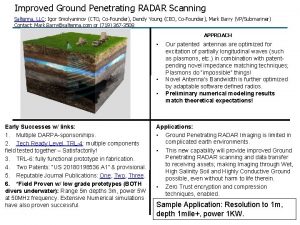
USE GROUND PENETRATING RADAR TECHNOLOGY TO EVALUATE RUTTING


- Slides: 20

USE GROUND PENETRATING RADAR TECHNOLOGY TO EVALUATE RUTTING IN AN ASPHALT OVERLAY Feng Hong, PE, Ph. D, Tx. DOT Darhao Chen, PE, Ph. D, Tx. DOT September 16~19, 2013, RPUG Meeting, San Antonio, TX

Table of Contents 1 Introduction 3 2 Background 4 -6 3 Experimental Design 4 Nondestructive Testing with GPR 8 -16 5 Trench Verification 17 -18 6 Conclusion Remarks 7 19 2

Introduction § What is rut § Causes of rut § Layer-based rut study § Methods to evaluate layer-based rut § Focus of this study 3

Background (1) Pavement structure Project history Hot rubber seal ~2” Ty. C HMA ~4~5” Ty. B HMA ~8” CRC ~6” CTB § Hot rubber seal: 2006 § Hot mix asphalt overlay: 1998 Seal coat Fabric underseal Traffic § 2010 AADT: 24610 § Truck percentage: 26% § 20 years ESALs: 33 million Subgrade 4

Background (2) 5

Background (3) 6

Experimental Design Non destructive testing § Ground Penetrating Radar used to estimate pavement layer thickness § Right wheel path § Middle of lane Destructive testing § Coring used to calibrate GPR thickness estimates § Trenching used to verify permanent deformation estimated by GPR NDT and DT complement each other to accommodate evaluation of permanent deformation across the entire length of the segment under study. 7

GPR Principle Pavement 8

GPR Colorful Map View 9

Thickness Estimation Based on GPR Signal Dielectric A 1: Amplitude of reflection from pavement surface, in volt; Am: Amplitude of reflection from a metal plate (placed on a pavement surface), in volt. Thickness c: A constant representing the speed of the EM wave traveling in the air, i. e. approximately 3 x 10⁸ m/s or 11. 8 inch/ns; and t: One way travel time of an EM wave in a given layer. 10

Total AC Overlay Thickness Middle of Lane Right Wheel Path 11

AC Layer Thickness Along Different Scan Lines Right Wheel Path Middle of Lane 12

Thickness Calibration 13

Calibration Results 14

Layer Based Thickness Comparison AC Layer 1 AC Layer 2 15

Layer Based Permanent Deformation Statistics 16

Trenching in Field 17

Permanent Deformation from Trench PD (in. ) GPR Trench Layer 1 0. 63 Layer 2 0. 27 0. 38 18

Conclusion Remarks § GPR can serve as an effective tool to – Evaluate permanent deformation in AC overlay – Identify layer-based permanent deformation – Provide full length survey coverage – Provide fast and nondestructive survey results 19

Thank You & Be Safe 20
 Civil engineering applications of ground penetrating radar
 Saltenna
 Mti radar with power amplifier transmitter
 Frequency response of single delay line canceller
 Cell penetrating peptides
 Fornix based conjunctival flap
 What is synthetic substitution
 Use synthetic substitution to evaluate
 Inappropriate use of technology in the workplace
 How to use technology responsibly
 Unit 1 technology in use
 Unit 1 technology in use
 Introduction of storage devices
 Common business tools and technologies
 Yawnproof
 How you use ict today and how you will use it tomorrow
 Practice 8-1 zero and negative exponents
 Unit 4 crime and punishment
 Sin cos tan table
 Expression vs equation
 Cognitive approach definition
