LANDMINE DETECTION USING IMPULSE GROUND PENETRATING RADAR SHARATH


 are a legacy of war” What are Landmines?")
 AT are designed to destroy tanks and")


 used by Im.")


- Slides: 22
LANDMINE DETECTION USING IMPULSE GROUND PENETRATING RADAR SHARATH
INTRODUCTION HARDWARE DESCRIPTION OVERVIEW OF THE SYSTEM TESTING AND EVALUATION CONCLUSION
INTRODUCTION “Landmines and unexploded ordnance (UXO) are a legacy of war” What are Landmines? Landmines are container ofexplosives that are triggered by contact with a person or vehicles. What are UXO? whose UXO are bombs or fired rocket launchers fuses did not detonate.
There are two types of Landmines �Anti-tank(AT) AT are designed to destroy tanks and armored vehicles. �Anti-personnel(AP) Is an explosive device made to injure or kill a person.
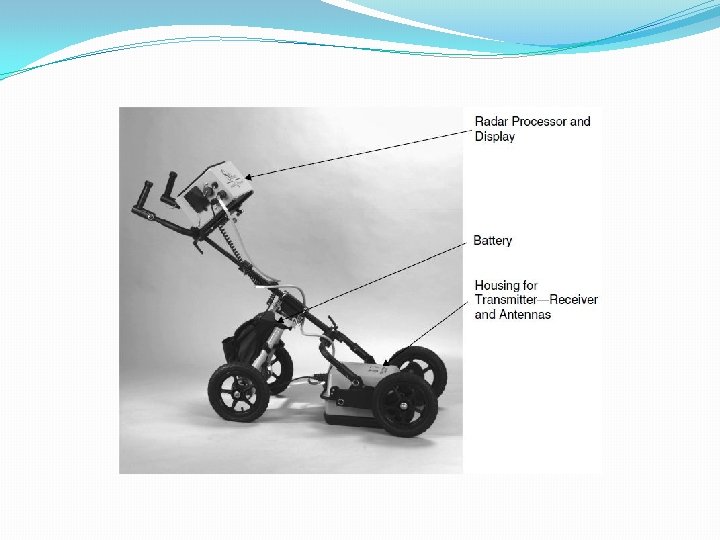
Hardware Description Impulse GPR system comprises an Impulse generator, Transmitter, Receiver, Pulse extender, A/D converter, Processor and Visual display.
Impulse Generator �The pulse generator delivered by SATIS Co. produces 0. 8 ns monocycle pulses. �Covers a wide frequency band from 500 MHz till 2 GHz. �It was found experimentally that the 0. 8 ns monocycle satisfies penetration and resolution requirements. Output signal from 0. 8 ns generator
Antenna System The GPR System’s performance strongly depends on the antenna system. The antenna system consist of transmitter and receiver. The transmit antenna should: �Radiate ultra-wide band (UWB). �Radiate electro magnetic energy. �Produce an optimal footprint. �Type of the ground.
The Receiver antenna should: �sufficient sensitivity in order to receive very weak fields. �Receive the field in a local point. �Be elevated at least 10 cm above the ground surface.
Pulse Extender Pulse extender will amplify the ground reflection. A/D Converter TXr RXr High speed sampler A/D converter. �Center frequency and Bandwith.
PROCESSOR �A/D converter Processor. �Processes the signal. �Presence or absence of surrogate mine. �Mine detecting signal Visual display.
Visual Display �Range of targets. �Exact position.
OVERVIEW OF THE SYSTEM �A series of measurements has been taken using a set of targets buried in the various types of soil. �An FR-127 -MSCB (Im. GPR) developed by CSIRO. �System collects 127 echos or surroundings per second. �Each composed of 512 samples with 12 bit accuracy. �Sounding range vary from 4 ns to 32 ns. �GPR uses bistatic bow-tie antenna which transmits wideband, ultra short duration pulses.
�GPR unit is suspended at a height between 0. 5 to 2 cm. �Motion controlled by stepper motor. �With constant speed, straight track, these samples corresponds to distances from starting point of the run.
�GPR images the dielectric properties of the soil. �Automatic Targets Recognition(ATR) used by Im. GPR. �Measurments form a two dimentional matrix reffered as Radargram or B scan and A scan.
A-Scan �Presence or absence of surrogate mine. �The Elecromagnetic field is scattered. �The graph is Amplitude Vs Time �Graph is used for visual inspection.
B-Scan �Visualise the target of surrogate mine. �B-san calculates distance from soil to the mine. �Shows target at 55 cm and 100 cm. �Graph helps to calculate the distance from ground to mine.
Deployment Platform �As technological development for land mine detection tends to be a vehicular based system.
Testing and Evaluation �US Army performs test at their testing facilities, which include carefully constructed mine lines. �Testing and Evaluation environment, landmines are live. �Dirt and gravel lanes are maintained.
Advantages �GPR has accurate measurements. �GPR locates even small targets. �It has been well founded by the defense. �Biological sensors can only operate for limited periods, but in GPR has no such limits. �GPR has been tested in different environmental conditions. Disadvantages �The sensor such as GPR is larger and heavier. �GPR is more power hungry. �GPR can suffer falls alarm rates as high as metal detectors. �GPR can be very effective or ineffective, depending on soil moisture and mine location.
Conclusion �Impulse GPR system is using for detecting anti-tank and anti-personal mines. � Currently, very little technology is used in real-world demining activities. �Active programs by the U. S Army in both land mine detection sensor development and systems integration are evaluating new technologies, incrementally improving existing technologies, increasing the probability of detection, reducing the false alarm rate, and planning out useable deployment scenarios. �Through iterative design, build test cycles, and blind and scored testing at Army mine lanes, steady progress is being made.
THANK YOU