Equipment for Mechanical Alloying The process of mechanical


- Slides: 39


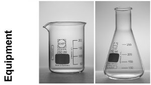
Equipment for Mechanical Alloying The process of mechanical alloying (MA) starts with mixing of the powders in the desired proportion and loading of the powder mix in to the mill along with the grinding medium (generally steel balls). Alloying is not required to occur during mechanical milling (MM) (since one starts with pre-alloyed powders or materials with uniform composition throughout), but only particle/grain refinement and/or some phase transformations should take place. The important components of the MA process are the raw materials, the mill, and the process variables.

Figure 4. 1 Schematic of the deferent steps involved in producing a product from powders by the mechanical alloying route.

RAW MATERIALS The raw materials used for MA are the widely available commercially pure powders that have particle sizes in the range of 1– 200 μm. However, the powder particle size is not very critical, except that it should be smaller than the grinding ball size. The raw powders fall into the broad categories of pure metals, master alloys, prea-lloyed powders, and refractory compounds. The impurity of raw powders (such as oxygen)!!!! Amount of impurities in the system decides the type of the final phase formed, chemical constitution of the alloy, and the kinetics of transformations. Raw material powders of di�erent purity and sizes can be obtained from standard suppliers like Goodfellow Metals, Alfa Aesar, and so forth.

TYPES OF MILLS Di�erent types of high-energy milling equipment are used to produce mechanically alloyed/milled powders. They di�er in their design, capacity, e�ciency of milling, and additional arrangements for cooling, heating, and so forth. The following sections describe some of the more common mills currently in use for MA/MM, which are also readily available in the market.

Spex Shaker Mills • Shaker mills, such as SPEX mills • Fig. 4 -2 Mill about 10– 20 g of the powder at a time, are most commonly used for laboratory investigations and for alloy screening purposes. These mills are manufactured by SPEX Cert. Prep (203 Norcross Avenue, Metuchen, NJ 08840, Tel: 1 -800 -5227739 or 732 -549 -7144; www. spexcsp. com).

Spex Shaker Mills • The common version of APEX mill has one vial, containing the powder sample and grinding balls, secured in the clamp and swung energetically back and forth several thousand times a minute. • The back-and-forth shaking motion is combined with lateral movements of the ends of the vial, so that the vial appears to be describing a figure of 8 or infinity symbol as it moves. • A variety of vial materials is available for the SPEX mills; these include hardened steel, alumina, tungsten carbide, zirconia, stainless steel, silicon nitride, agate, plastic, and methacrylate.

Spex Shaker Mills • SPEX mills have certain disadvantages. • First, the balls may roll around the end of the vial rather than hitting it; this decreases the intensity of milling. • Second, the powder may collect in the eyes of the ‘‘ 8’’ and remain unprocessed. • Last, the round-ended vial is rather heavy; the flat-ended vial is 30% lighter, and impacts at the ends of the vial dominate the milling action. However, some powder may collect at the edges and remain unprocessed.

Planetary Ball Mills Another popular mill for conducting MA experiments is the planetary ball mill (referred to as Pulverisette) in which a few hundred grams of the powder can be milled at the same time.

Planetary Ball Mills • The planetary ball mill owes its name to the planet-like movement of its vials. • These arranged on a rotating support disk, and a special drive mechanism causes them to rotate around their own axes. • The centrifugal force produced by the vials rotating around their own axes and that produced by the rotating support disk both act on the vial contents, consisting of the material to be ground and the grinding balls.

Planetary Ball Mills • Since the vials and the supporting disk rotate in opposite directions, the centrifugal forces alternately act in like and opposite directions: • This causes the grinding balls to run down the inside wall of the vial—the friction e�ect • The material being ground and the grinding balls lifting o� and traveling freely through the inner chamber of the vial and colliding with the opposing inside wall—the impact e�ect • The grinding balls impacting with each other intensify the impact e�ect considerably.

Planetary Ball Mills As the speed is reduced, the grinding balls lose the impact energy, and when the energy is su�ciently low there is no grinding involved; only mixing occurs in the sample.

Planetary Ball Mills • Even though the disk and the vial rotation speeds could not be independently controlled in the early versions, it is possible to do so in the modern versions of the Fritsch planetary ball mills. In a single mill one can have either two (Pulverisette 5 or 7) or four (Pulverisette 5) milling stations. • Di�erent sizes of containers (vial/cup) • Different grinding vials and balls

Planetary Ball Mills • A recent development in the design of the Fritsch mills has been the incorporation of a gas pressure and temperature measuring system (GTM) for in situ data acquisition during milling

Attritor Mills • A conventional ball mill consists of a rotating horizontal drum half-filled with small steel balls. • An attritor (a ball mill capable of generating higher energies) consists of a vertical drum containing a series of impellers. • A powerful motor rotates the impellers, which in turn agitate the steel balls in the drum.

Attritor Mills • As the drum rotates the balls drop on the metal powder that is being ground; the rate of grinding increases with the speed of rotation. • At high speeds, however, the centrifugal force acting on the steel balls exceeds the force of gravity, and the balls are pinned to the wall of the drum. At this point the grinding action stops. • The dry particles are subjected to various forces such as impact, rotation, tumbling, and shear.

Attritor Mills • Powder size reduction because of collisions between balls, between balls and container wall, and between balls, agitator shaft, and impellers. Therefore, micrometer-range fine powders can be easily produced. • Some size reduction, though small in proportion, appears to take place by interparticle collisions and by ball sliding. • In addition, combination of these forces creates a more spherical particle than other impact-type milling equipment.

Attritor Mills Attritors, also known as stirred ball mills: The mills in which large quantities of powder (from a few pounds to about 100 lb) can be milled at a time

Attritor Mills • The velocity of the grinding medium in the attritors is much lower (about 0. 5 m/s) than in the planetary or SPEX mills • Then, the energy of milling in the attritors is low. • Di�erent sizes/capacities are available and different grinding media • While the attritors are generally batch type, they can be made to work in a continuous mode.

Attritor Mills • Attritors, use grinding medium of about 1/8 to 3/8 in. size and run typically at moderate speeds of about 60 rpm in the largest production size units, but at about 250 rpm for the laboratory size units. • The most important concept in the attritor is that the power input is used directly for agitating the media to achieve grinding and is not used for rotating or vibrating a large, heavy tank in addition to the media.

Fig. 4 -8

Attritor Mills • While the Union Process attritors are vertical in configuration, the Zoz attritors are horizontal (Fig. 4. 9). • The main features of the Zoz attritor (study from the ref. ).

Attritor Mills • The main problem of the horizontal attritors is that very fine powder prepared in the attritor is not forced by gravity to places away from the rotary seals. This technical problem was solved by means of an adjustable preseal unit, an extension chamber, and finally a redesign of the rotary seal itself. • The advantages of the horizontal attritor are as follows: • • • 1 - No dead zones due to gravity 2 - Possibility of extremely high-energy impact 3 -Charging and discharging under controlled atmosphere

Commercial Mills • Commercial mills for MA are much larger in size than the mills described above and can process several hundred pounds of powder at a time. • MA for commercial production is carried out in ball mills of up to about 3000 lb (1250 kg) capacity. • Refer to Fig. 4. 11. • .

Commercial Mills The milling time decreases with an increase in the energy of the mill. It has been reported that 20 min of milling in a SPEX mill is equivalent to 20 h of milling in a low energy mill of the Invicta BX 920/2 type. As a rule of thumb, it can be estimated that a process that takes only a few minutes in the SPEX mill may take hours in an attritor and a few days in a commercial mill, even though the details can di�er depending on the e�ciency of the di�erent mills.

Commercial Mills Figure 4. 12 shows the times required to reach a specific particle size during milling in a planetary ball mill and an attritor. It may be noted that the times are an order of magnitude shorter in the attritor. • See Fig. 4 -13

New Designs Several new designs of mills have been developed in recent years for specialized purposes. These include the rod mills, vibrating frame mills, and the equipment available from Dymatron (Cincinnati, OH), Nisshin Giken (Tokyo, Japan), Australian Scientific Instruments (Canberra, Australia), and M. B. N. srl (Rome, Italy). The rod mills are very similar to the ball mills except that they use steel rods instead of balls as grinding medium. It has been claimed that the powder contamination during rod milling is much lower than during ball milling. This has been explained to be due to the increased proportion of shear forces over the impact forces during rod milling.

New Designs • The Megapact and Megamill-5 units supplied by Dymatron are high-energy vibration mills. • The Megapact mill (see Fig. 4. 14 a)

New Designs The Uni-Ball mill from Australian Scientific Instruments (Canberra, Australia) is another type of mill wherein it is possible to control the nature and magnitude of impact of the balls by controlling the field strength with the help of adjustable magnets. The incorporation of permanent magnets generates a magnetic field, which acts on the ferromagnetic balls used for milling. By adjusting the distance between the balls and the magnet, the impact energy can be varied. Thus, one can choose the desired impact energy depending on the requirement and the materials to be milled. By proper adjustment of the magnetic field, the e�ective mass of the grinding ball can be increased by a factor of 80. Furthermore, changing the positions of the magnets can alter the type of energy transferred to the powder and one can obtain impact or shear modes or a combination of both.

The Uni-Ball mill has the following special features: 1 - Multiple mill chambers allowing large amount of powder to be processed at a time. 2 - Precision control of milling energy by properly adjusting the position, quantity, and proximity of the magnets around each mill chamber. This allows the user to select the impact energy, shear force and the proportion of these. 3 - Variable milling speed. 4 - Fully controlled atmosphere (argon, nitrogen, helium, ammonia, hydrogen, etc. ). 5 - Fully controlled temperature (from low to high temperatures of about 200 j. C).

New Designs • For other new designs, Please see, section (4. 3. 5) and related figures.

Table 4. 1 summarizes the capacities of the di�erent mills for MA/MM that are commercially available.

Figure 4. 20 compares the di�erent devices (Simoloyer, planetary ball mill, attritor, and a conventional ball mill) regarding their sizes and capacities .

• The main goal of the design of any MA/MM device is to produce homogeneous powder of the desired stoichiometry in an economical way and with the required purity (minimal or no contamination). • It would also be useful to increase the productivity without increasing the milling time, and it is most desirable for the powder to be produced continuously.

SELECTION OF GRINDING MEDIUM Proper selection of the nature, size, and size distribution of the grinding medium is an important step in achieving e�cient milling of powder particles. The selection depends on several factors: Specific Gravity: In general, high-density media give better results. This is because the kinetic energy of the balls is higher and consequently higher amounts of energy are transferred to the milled powder. The media should be denser than the powder being ground. Also, highly viscous materials require media with a higher density to prevent floating.

SELECTION OF GRINDING MEDIUM Initial Feed Size: • Since smaller media cannot break up large particles, the grinding medium should be larger than the powder particle size. • It is desirable to use a mixture of di�erent sizes of the balls rather than one size. A mixture of di�erent sizes of the grinding balls helps to improve the e�ciency of the attritor. Final Particle Size • The grinding medium should be smaller when very fine particles are desired; the smaller the grinding medium, the smaller is the final particle size.

SELECTION OF GRINDING MEDIUM Hardness The harder the media the lesser is the powder contamination, and consequently the medium lasts longer. If the medium is brittle, then edges of the medium may be chipped o� and get incorporated into the milled powder and contaminate it. If the media is magnetic in nature and the powder is not, then the material resulting from the wear of the grinding medium may be separated by magnetic means. p. H Value Some strong acid or basic slurries may react with certain metallic media.

SELECTION OF GRINDING MEDIUM Discoloration Certain media result in color development and are, therefore, not suitable in the production of some materials such as white coatings. Contamination This could be a serious consideration since material resulting from the wear of the media a�ects the product and may contaminate it. Therefore, it should be removed by a magnetic separator, chemicals, or sintering.

SELECTION OF GRINDING MEDIUM Cost Media that are two to three times more expensive may last considerably longer. These may be well worth the extra cost over the long run. Table 4. 2 presents the di�erent types of grinding media available for MA/MM purposes and their properties.
 Mechanical process equipment
 Mechanical measuring devices
 Fspos
Fspos Typiska novell drag
 Nationell inriktning för artificiell intelligens
 Vad står k.r.å.k.a.n för
 Varför kallas perioden 1918-1939 för mellankrigstiden
 En lathund för arbete med kontinuitetshantering
 Kassaregister ideell förening
 Tidbok för yrkesförare
 Sura för anatom
 Förklara densitet för barn
 Datorkunskap för nybörjare
 Stig kerman
 Mall debattartikel
 För och nackdelar med firo
 Nyckelkompetenser för livslångt lärande
 Påbyggnader för flakfordon
 Vätsketryck formel
 Svenskt ramverk för digital samverkan
 Jag har nigit för nymånens skära
 Presentera för publik crossboss
 Jiddisch
 Kanaans land
 Treserva lathund
 Epiteltyper
 Bästa kameran för astrofoto
 Cks
Cks Programskede byggprocessen
 Mat för unga idrottare
 Verktyg för automatisering av utbetalningar
 Rutin för avvikelsehantering
 Smärtskolan kunskap för livet
 Ministerstyre för och nackdelar
 Tack för att ni har lyssnat
 Referat mall
 Redogör för vad psykologi är
 Borstål, egenskaper
 Atmosfr
 Borra hål för knoppar
