EPFL Spring 2017 3 PLC Programming The long
- Slides: 68
EPFL, Spring 2017 3 PLC Programming
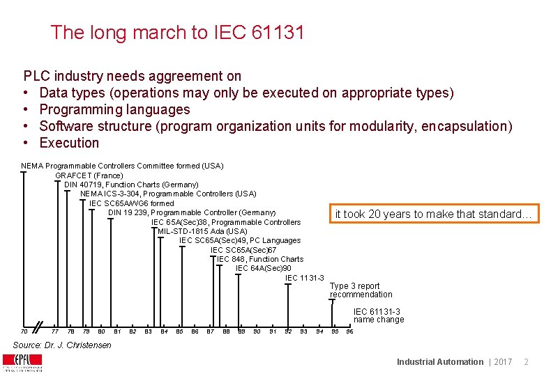
The long march to IEC 61131 PLC industry needs aggreement on • Data types (operations may only be executed on appropriate types) • Programming languages • Software structure (program organization units for modularity, encapsulation) • Execution NEMA Programmable Controllers Committee formed (USA) GRAFCET (France) DIN 40719, Function Charts (Germany) NEMA ICS-3 -304, Programmable Controllers (USA) IEC SC 65 A/WG 6 formed DIN 19 239, Programmable Controller (Germany) IEC 65 A(Sec)38, Programmable Controllers MIL-STD-1815 Ada (USA) IEC SC 65 A(Sec)49, PC Languages IEC SC 65 A(Sec)67 IEC 848, Function Charts IEC 64 A(Sec)90 IEC 1131 -3 it took 20 years to make that standard… Type 3 report recommendation IEC 61131 -3 name change 70 77 78 79 80 81 82 83 84 85 86 87 88 89 90 91 92 93 94 95 96 Source: Dr. J. Christensen Industrial Automation | 2017 2
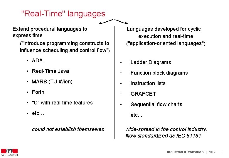
"Real-Time" languages Extend procedural languages to express time Languages developed for cyclic execution and real-time ("application-oriented languages") (“introduce programming constructs to influence scheduling and control flow”) • ADA • Ladder Diagrams • Real-Time Java • Function block diagrams • MARS (TU Wien) • Instruction lists • Forth • GRAFCET • “C” with real-time features • Sequential flow charts • etc… could not establish themselves etc. . . wide-spread in the control industry. Now standardized as IEC 61131 Industrial Automation | 2017 3
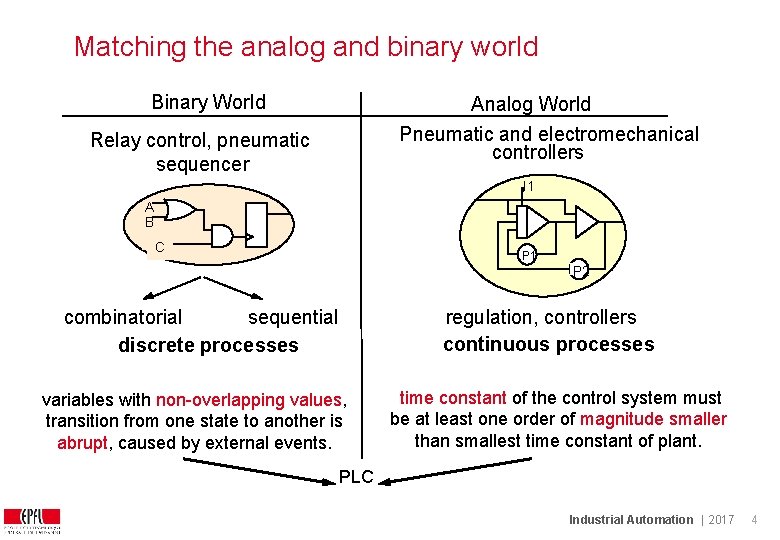
Matching the analog and binary world Binary World Analog World Pneumatic and electromechanical controllers Relay control, pneumatic sequencer I 1 A B C P 1 P 2 regulation, controllers continuous processes combinatorial sequential discrete processes variables with non-overlapping values, transition from one state to another is abrupt, caused by external events. time constant of the control system must be at least one order of magnitude smaller than smallest time constant of plant. PLC Industrial Automation | 2017 4
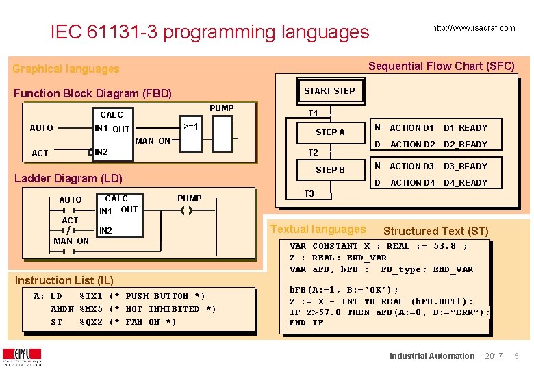
IEC 61131 -3 programming languages Sequential Flow Chart (SFC) Graphical languages START STEP Function Block Diagram (FBD) PUMP CALC AUTO >=1 IN 1 OUT T 1 DO STEP A V MAN_ON IN 2 ACT T 2 STEP B Ladder Diagram (LD) AUTO ACT http: //www. isagraf. com CALC IN 1 OUT PUMP IN 2 MAN_ON Instruction List (IL) A: LD %IX 1 (* PUSH BUTTON *) ANDN %MX 5 (* NOT INHIBITED *) ST %QX 2 (* FAN ON *) N ACTION D 1_READY D ACTION D 2_READY N ACTION D 3_READY D ACTION D 4_READY T 3 Textual languages Structured Text (ST) VAR CONSTANT X : REAL : = 53. 8 ; Z : REAL; END_VAR a. FB, b. FB : FB_type; END_VAR b. FB(A: =1, B: =‘OK’); Z : = X - INT_TO_REAL (b. FB. OUT 1); IF Z>57. 0 THEN a. FB(A: =0, B: =“ERR”); END_IF Industrial Automation | 2017 5
Importance of IEC 61131 -3 are the most important automation languages in industry. 80% of all PLCs support it, all new developments are based on it. Depending on the country, some languages are more popular than others. IEC 61499 extends IEC 61131 with an event-driven model, has not established itself yet. More information: http: //www. plcopen. org/pages/tc 1_standards/downloads/plcopen_iec 611313_feb 2014. pptx http: //www. plcopen. org/pages/pc 2_training/downloads/index. htm Industrial Automation | 2017 6
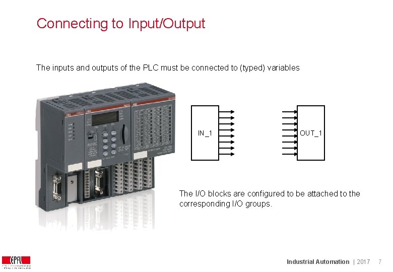
Connecting to Input/Output The inputs and outputs of the PLC must be connected to (typed) variables IN_1 OUT_1 The I/O blocks are configured to be attached to the corresponding I/O groups. Industrial Automation | 2017 7
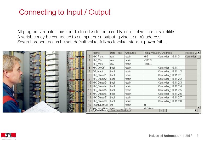
Connecting to Input / Output All program variables must be declared with name and type, initial value and volatility. A variable may be connected to an input or an output, giving it an I/O address. Several properties can be set: default value, fall-back value, store at power fail, … Industrial Automation | 2017 8
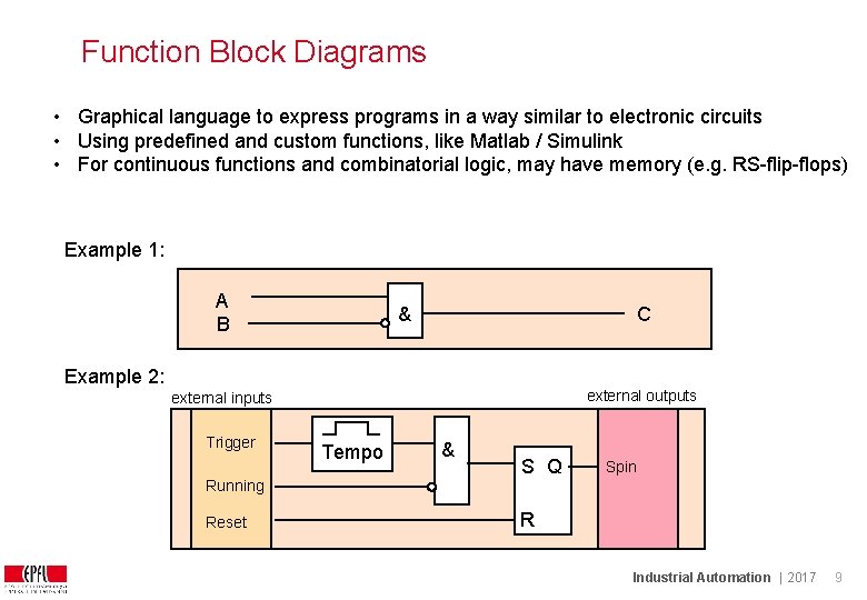
Function Block Diagrams • Graphical language to express programs in a way similar to electronic circuits • Using predefined and custom functions, like Matlab / Simulink • For continuous functions and combinatorial logic, may have memory (e. g. RS-flip-flops) Example 1: A B & C Example 2: external outputs external inputs Trigger Running Reset Tempo & S Q Spin R Industrial Automation | 2017 9
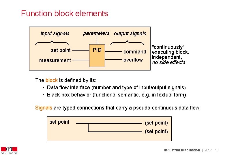
Function block elements input signals set point measurement parameters output signals PID command overflow "continuously" executing block, independent, no side effects The block is defined by its: • Data flow interface (number and type of input/output signals) • Black-box behavior (functional semantic, e. g. in textual form). Signals are typed connections that carry a pseudo-continuous data flow set point (set point) Industrial Automation | 2017 10
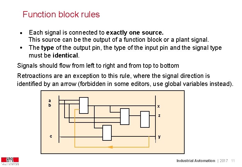
Function block rules Each signal is connected to exactly one source. This source can be the output of a function block or a plant signal. • The type of the output pin, the type of the input pin and the signal type must be identical. • Signals should flow from left to right and from top to bottom Retroactions are an exception to this rule, where the signal direction is identified by an arrow (forbidden in some editors, use global variables instead). a b x z c y Industrial Automation | 2017 11
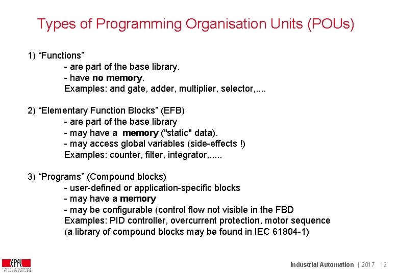
Types of Programming Organisation Units (POUs) 1) “Functions” - are part of the base library. - have no memory. Examples: and gate, adder, multiplier, selector, . . 2) “Elementary Function Blocks” (EFB) - are part of the base library - may have a memory ("static" data). - may access global variables (side-effects !) Examples: counter, filter, integrator, . . . 3) “Programs” (Compound blocks) - user-defined or application-specific blocks - may have a memory - may be configurable (control flow not visible in the FBD Examples: PID controller, overcurrent protection, motor sequence (a library of compound blocks may be found in IEC 61804 -1) Industrial Automation | 2017 12
Function block library The programmer chooses the blocks in a block library, similarly to the hardware engineer who chooses integrated circuits in a catalogue. The library describes the pinning of each block, its semantics and the execution time. The programmer may extend the library by defining function block macros composed of library elements. If some blocks are used often, they will be programmed in an external language (e. g. “C”, micro-code) following strict rules. Industrial Automation | 2017 13
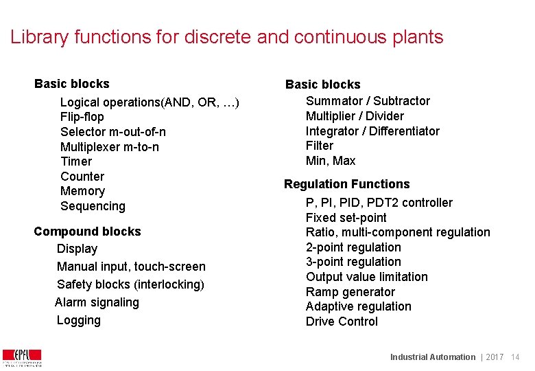
Library functions for discrete and continuous plants Basic blocks Logical operations(AND, OR, …) Flip-flop Selector m-out-of-n Multiplexer m-to-n Timer Counter Memory Sequencing Compound blocks Display Manual input, touch-screen Safety blocks (interlocking) Alarm signaling Logging Basic blocks Summator / Subtractor Multiplier / Divider Integrator / Differentiator Filter Min, Max Regulation Functions P, PID, PDT 2 controller Fixed set-point Ratio, multi-component regulation 2 -point regulation 3 -point regulation Output value limitation Ramp generator Adaptive regulation Drive Control Industrial Automation | 2017 14
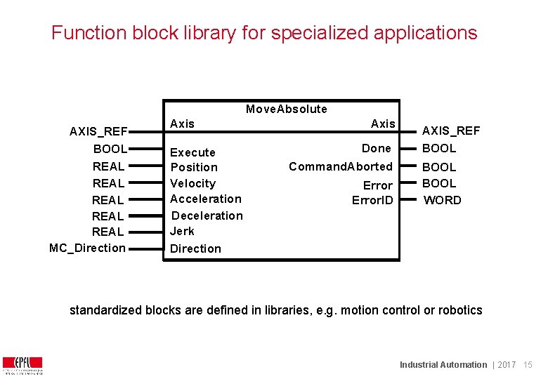
Function block library for specialized applications Move. Absolute AXIS_REF BOOL REAL REAL MC_Direction Axis Execute Position Velocity Acceleration Deceleration Jerk Direction Axis Done Command. Aborted Error. ID AXIS_REF BOOL WORD standardized blocks are defined in libraries, e. g. motion control or robotics Industrial Automation | 2017 15
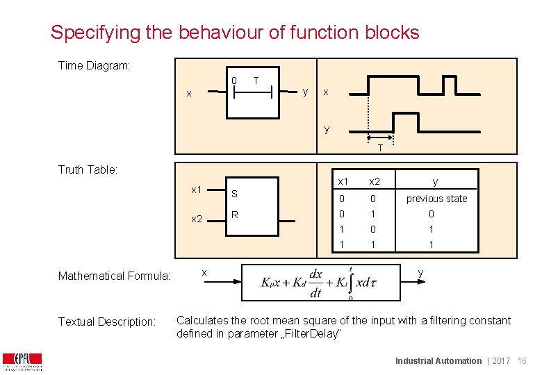
Specifying the behaviour of function blocks Time Diagram: 0 x T y x y T Truth Table: Mathematical Formula: Textual Description: x 1 x 2 x x 1 x 2 y S 0 0 previous state R 0 1 0 1 1 y Calculates the root mean square of the input with a filtering constant defined in parameter „Filter. Delay“ Industrial Automation | 2017 16
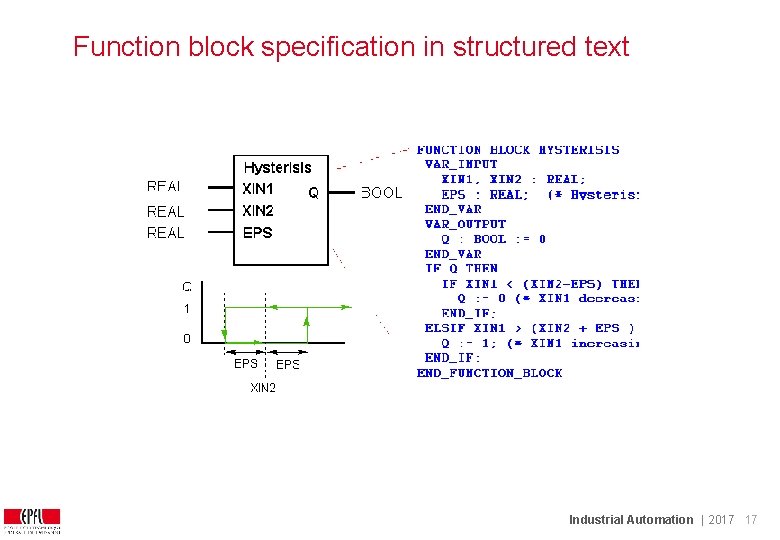
Function block specification in structured text Industrial Automation | 2017 17
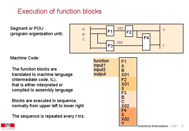
Execution of function blocks Segment or POU (program organization unit) A B C F 1 The function blocks are translated to machine language (intermediate code, IL), that is either interpreted or compiled to assembly language Blocks are executed in sequence, normally from upper left to lower right The sequence is repeated every t ms. X F 2 F 4 F 3 Machine Code: X 01 function input 1 input 2 output X 02 F 1 A B X 01 F 2 X 01 X F 3 B C X 02 F 4 X X 02 Y Y Industrial Automation | 2017 18
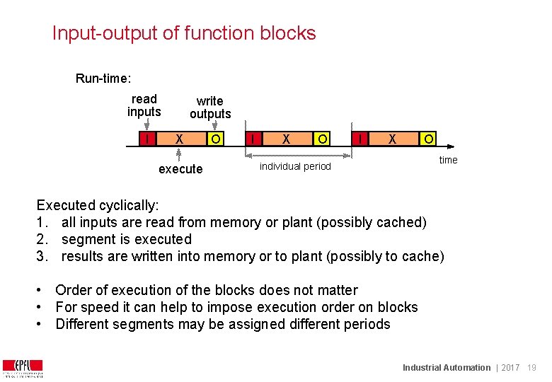
Input-output of function blocks Run-time: read inputs I write outputs X execute O I X O time individual period Executed cyclically: 1. all inputs are read from memory or plant (possibly cached) 2. segment is executed 3. results are written into memory or to plant (possibly to cache) • Order of execution of the blocks does not matter • For speed it can help to impose execution order on blocks • Different segments may be assigned different periods Industrial Automation | 2017 19
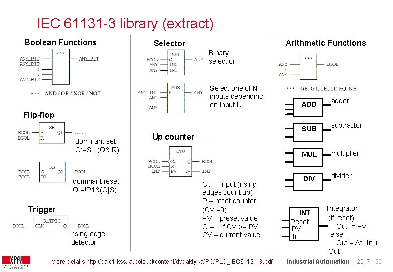
IEC 61131 -3 library (extract) Boolean Functions Arithmetic Functions Selector Binary selection Select one of N inputs depending on input K ADD adder SUB subtractor MUL multiplier DIV divider Flip-flop dominant set Q: =S 1|(Q&!R) dominant reset Q: =!R 1&(Q|S) Trigger rising edge detector Up counter CU – input (rising edges count up) R – reset counter (CV: =0) PV – preset value Q – 1 if CV >= PV CV – current value More details http: //calc 1. kss. ia. polsl. pl/content/dydaktyka/PC/PLC_IEC 61131 -3. pdf INT Reset PV In Integrator (if reset) Out : = PV, else Out: = Δt *In + Out Industrial Automation | 2017 20
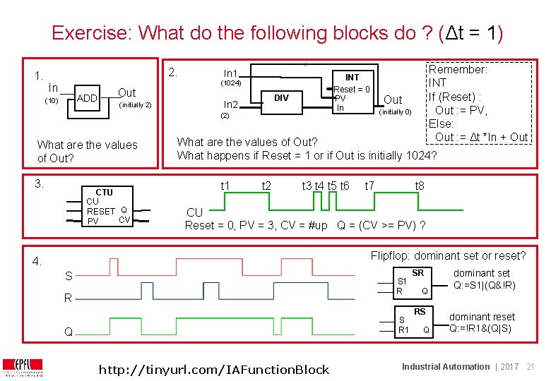
Exercise: What do the following blocks do ? (Δt = 1) 1. 2. In ADD (10) Out (initially 2) In 1 INT Reset = 0 PV In (1024) DIV In 2 (2) What are the values of Out? 3. CTU CU RESET Q CV PV Remember: INT If (Reset) : Out : = PV, Else: Out : = Δt *In + Out (initially 0) What are the values of Out? What happens if Reset = 1 or if Out is initially 1024? t 1 t 2 t 3 t 4 t 5 t 6 t 7 t 8 CU Reset = 0, PV = 3, CV = #up Q = (CV >= PV) ? Flipflop: dominant set or reset? 4. S S 1 R R S R 1 Q http: //tinyurl. com/IAFunction. Block SR Q RS Q dominant set Q: =S 1|(Q&!R) dominant reset Q: =!R 1&(Q|S) Industrial Automation | 2017 21
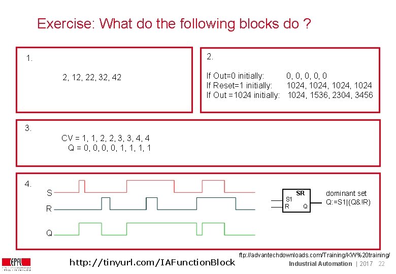
Exercise: What do the following blocks do ? 2. 1. 2, 12, 22, 32, 42 If Out=0 initially: 0, 0, 0 If Reset=1 initially: 1024, 1024 If Out =1024 initially: 1024, 1536, 2304, 3456 3. CV = 1, 1, 2, 2, 3, 3, 4, 4 Q = 0, 0, 1, 1, 1, 1 4. S S 1 R R SR Q dominant set Q: =S 1|(Q&!R) Q http: //tinyurl. com/IAFunction. Block ftp: //advantechdownloads. com/Training/KW%20 training/ Industrial Automation | 2017 22
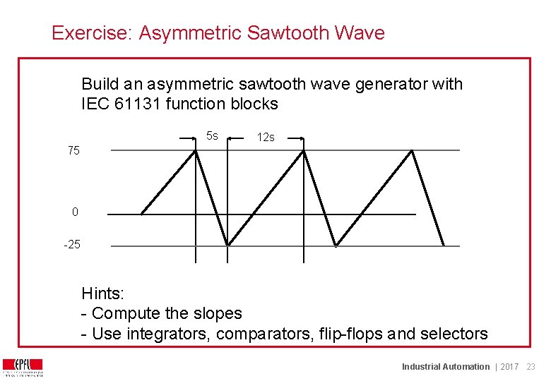
Exercise: Asymmetric Sawtooth Wave Build an asymmetric sawtooth wave generator with IEC 61131 function blocks 5 s 12 s 75 0 -25 Hints: - Compute the slopes - Use integrators, comparators, flip-flops and selectors Industrial Automation | 2017 23
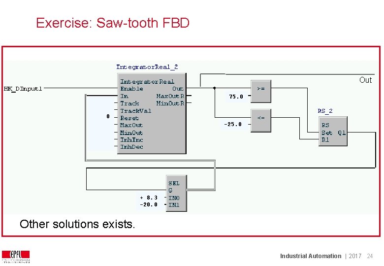
Exercise: Saw-tooth FBD Out 75. 0 0 -25. 0 + 8. 3 -20. 0 Other solutions exists. Industrial Automation | 2017 24
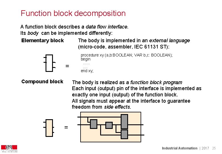
Function block decomposition A function block describes a data flow interface. Its body can be implemented differently: Elementary block The body is implemented in an external language (micro-code, assembler, IEC 61131 ST): = Compound block procedure xy (a, b: BOOLEAN; VAR b, c: BOOLEAN); begin. . end xy; The body is realized as a function block program. Each input (output) pin of the interface is implemented as exactly one input (output) of the function block. All signals must appear at the interface to guarantee freedom from side effects. = Industrial Automation | 2017 25
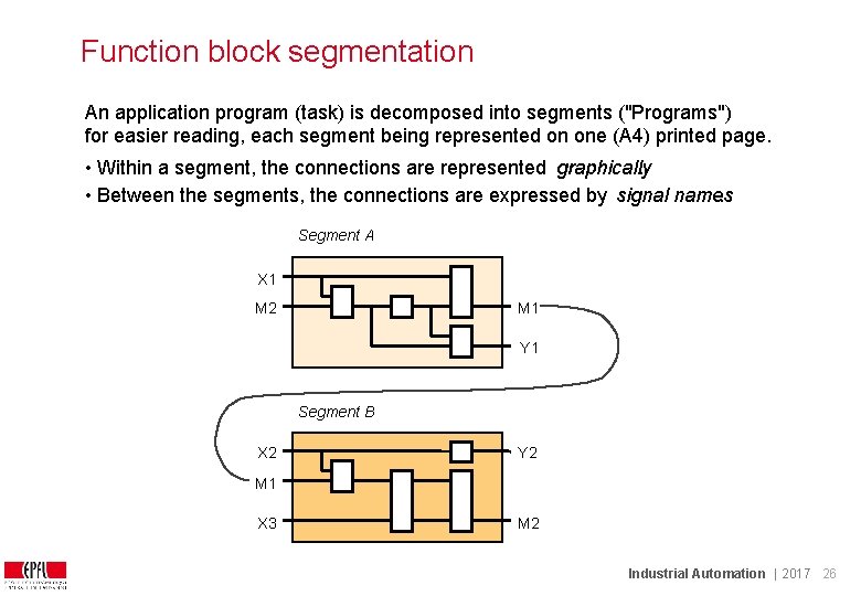
Function block segmentation An application program (task) is decomposed into segments ("Programs") for easier reading, each segment being represented on one (A 4) printed page. • Within a segment, the connections are represented graphically. • Between the segments, the connections are expressed by signal names. Segment A X 1 M 2 M 1 Y 1 Segment B X 2 Y 2 M 1 X 3 M 2 Industrial Automation | 2017 26
Structured Text (Strukturierte Textsprache, langage littéral structuré) Structured Text is an imperative language similar to Pascal (If, While, etc. . ) The variables defined in ST can be used in other languages ST is used for complex data manipulation and to write blocks Caution: writing programs in structured text can breach real-time rules ! Industrial Automation | 2017 27
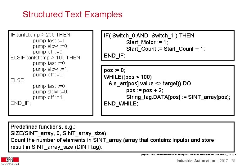
Structured Text Examples IF tank. temp > 200 THEN pump. fast : =1; pump. slow : =0; pump. off : =0; ELSIF tank. temp > 100 THEN pump. fast : =0; pump. slow : =1; pump. off : =0; ELSE pump. fast : =0; pump. slow : =0; pump. off : =1; END_IF; IF( Switch_0 AND Switch_1 ) THEN Start_Motor : = 1; Start_Count : = Start_Count + 1; END_IF; pos : = 0; WHILE((pos < 100) & s_arr[pos]. value <> target)) DO pos : = pos + 2; String_tag. DATA[pos] : = SINT_array[pos]; END_WHILE; Predefined functions, e. g. : SIZE(SINT_array, 0, SINT_array_size); Count the number of elements in SINT_array (array that contains inputs) and store result in SINT_array_size (DINT tag). [http: //literature. rockwellautomation. com/idc/groups/literature/documents/pm/1756 -pm 007_-en-p. pdf ] Industrial Automation | 2017 28
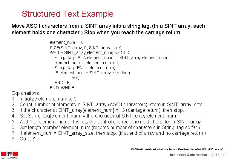
Structured Text Example Move ASCII characters from a SINT array into a string tag. (In a SINT array, each element holds one character. ) Stop when you reach the carriage return. element_num : = 0; SIZE(SINT_array, 0, SINT_array_size); WHILE SINT_array[element_num] <> 13 DO String_tag. DATA[element_num] : = SINT_array[element_num]; element_num : = element_num + 1; String_tag. LEN : = element_num; IF element_num = SINT_array_size then exit; END_IF; END_WHILE; Explanations: 1. Initialize element_num to 0. 2. Count number of elements in SINT_array (ASCII characters), store in SINT_array_size. 3. If the character at SINT_array[element_num] = 13 (carriage return), then stop. 4. Set String_tag[element_num] = the character at SINT_array[element_num]. 5. Add 1 to element_num. This lets the controller check the next character in SINT_array. 6. Set length member element_num (records number of characters in String_tag so far. ) 7. If element_num = SINT_array_size, then stop. (if at end of array and no carriage return. ) 8. Go to 3. [http: //literature. rockwellautomation. com/idc/groups/literature/documents/pm/1756 -pm 007_-en-p. pdf ] Industrial Automation | 2017 29
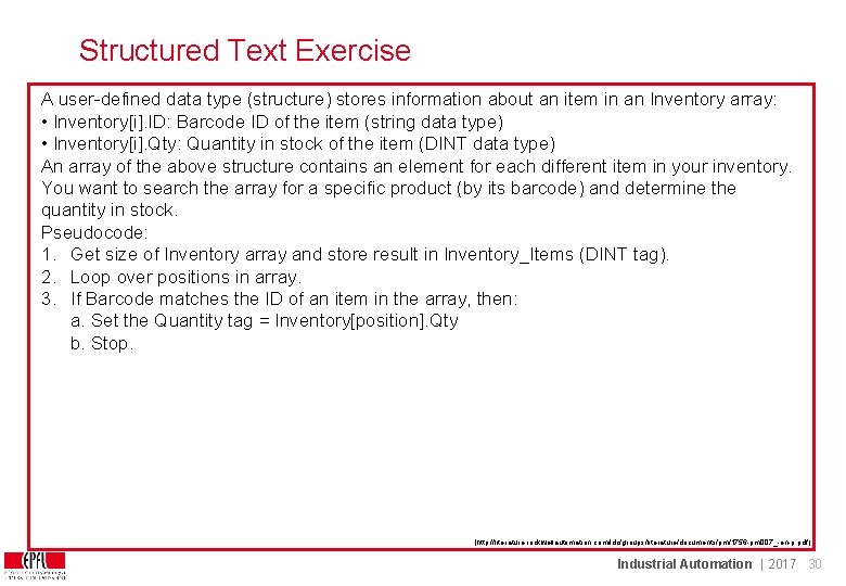
Structured Text Exercise A user-defined data type (structure) stores information about an item in an Inventory array: • Inventory[i]. ID: Barcode ID of the item (string data type) • Inventory[i]. Qty: Quantity in stock of the item (DINT data type) An array of the above structure contains an element for each different item in your inventory. You want to search the array for a specific product (by its barcode) and determine the quantity in stock. Pseudocode: 1. Get size of Inventory array and store result in Inventory_Items (DINT tag). 2. Loop over positions in array. 3. If Barcode matches the ID of an item in the array, then: a. Set the Quantity tag = Inventory[position]. Qty b. Stop. [http: //literature. rockwellautomation. com/idc/groups/literature/documents/pm/1756 -pm 007_-en-p. pdf ] Industrial Automation | 2017 30
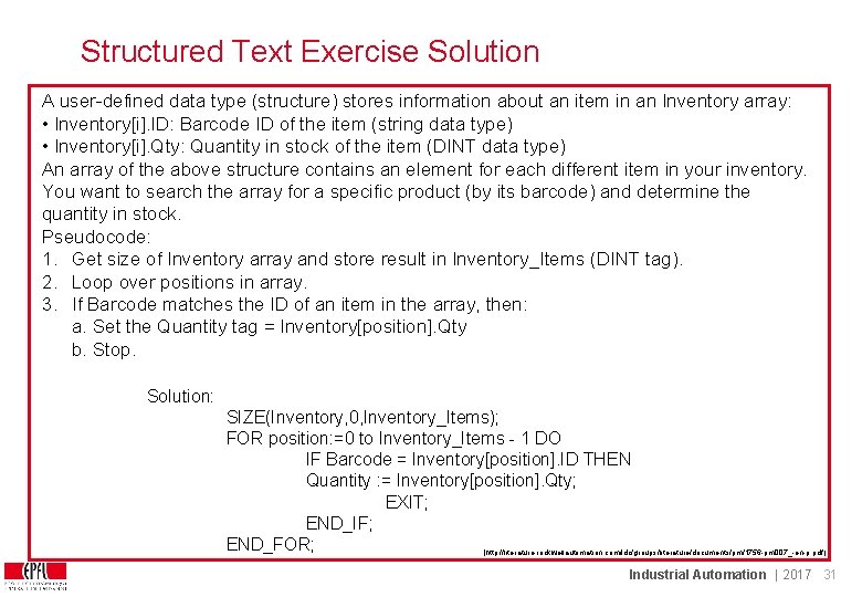
Structured Text Exercise Solution A user-defined data type (structure) stores information about an item in an Inventory array: • Inventory[i]. ID: Barcode ID of the item (string data type) • Inventory[i]. Qty: Quantity in stock of the item (DINT data type) An array of the above structure contains an element for each different item in your inventory. You want to search the array for a specific product (by its barcode) and determine the quantity in stock. Pseudocode: 1. Get size of Inventory array and store result in Inventory_Items (DINT tag). 2. Loop over positions in array. 3. If Barcode matches the ID of an item in the array, then: a. Set the Quantity tag = Inventory[position]. Qty b. Stop. Solution: SIZE(Inventory, 0, Inventory_Items); FOR position: =0 to Inventory_Items - 1 DO IF Barcode = Inventory[position]. ID THEN Quantity : = Inventory[position]. Qty; EXIT; END_IF; END_FOR; [http: //literature. rockwellautomation. com/idc/groups/literature/documents/pm/1756 -pm 007_-en-p. pdf ] Industrial Automation | 2017 31
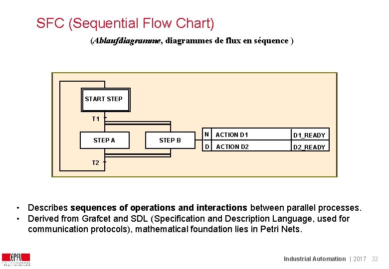
SFC (Sequential Flow Chart) (Ablaufdiagramme, diagrammes de flux en séquence ) START STEP T 1 STEP A STEP B N ACTION D 1_READY D ACTION D 2_READY T 2 • Describes sequences of operations and interactions between parallel processes. • Derived from Grafcet and SDL (Specification and Description Language, used for communication protocols), mathematical foundation lies in Petri Nets. Industrial Automation | 2017 32
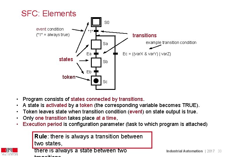
SFC: Elements S 0 event condition ("1" = always true) "1" transitions example transition condition Sa Ea states Ec = ((var. X & var. Y) | var. Z) Sb Eb token • • • Sc Program consists of states connected by transitions. A state is activated by a token (the corresponding variable becomes TRUE). Token leaves state when transition condition (event) on state output is true. Only one transition takes place at a time, Execution period is configuration parameter (task to which program is attached) Rule: there is always a transition between two states, there is always a state between two Industrial Automation | 2017 33
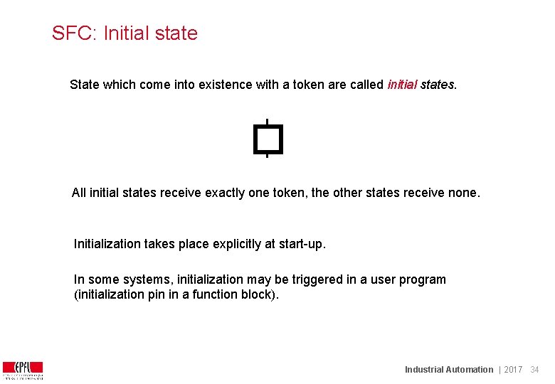
SFC: Initial state State which come into existence with a token are called initial states. All initial states receive exactly one token, the other states receive none. Initialization takes place explicitly at start-up. In some systems, initialization may be triggered in a user program (initialization pin in a function block). Industrial Automation | 2017 34
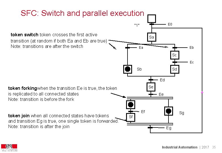
SFC: Switch and parallel execution E 0 "1" token switch: token crosses the first active transition (at random if both Ea and Eb are true) Note: transitions are after the switch Sa Ea Eb Sc Ec Sb Sd Ed Se token forking: when the transition Ee is true, the token is replicated to all connected states Note: transition is before the fork token join when all connected states have tokens and transition Eg is true, one single token is forwarded. Note: transition is after the join Ee Ef Sg Sf Eg Industrial Automation | 2017 35
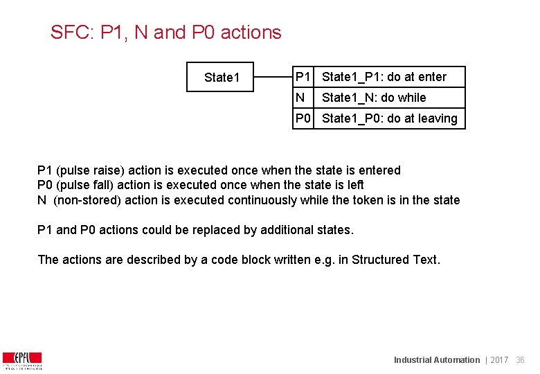
SFC: P 1, N and P 0 actions State 1 P 1 State 1_P 1: do at enter N State 1_N: do while P 0 State 1_P 0: do at leaving P 1 (pulse raise) action is executed once when the state is entered P 0 (pulse fall) action is executed once when the state is left N (non-stored) action is executed continuously while the token is in the state P 1 and P 0 actions could be replaced by additional states. The actions are described by a code block written e. g. in Structured Text. Industrial Automation | 2017 36
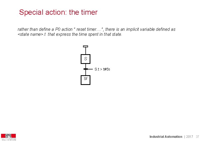
Special action: the timer rather than define a P 0 action “ reset timer…. ”, there is an implicit variable defined as <state name>. t that express the time spent in that state. S S. t > t#5 s Sf Industrial Automation | 2017 37
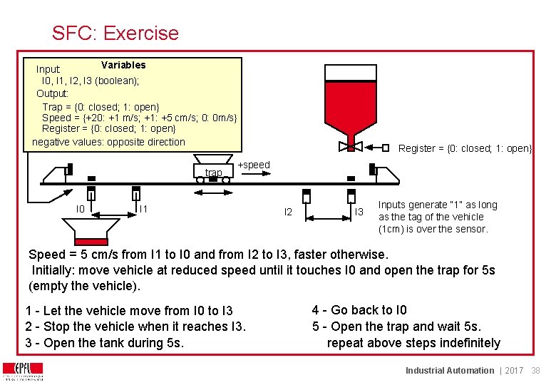
SFC: Exercise Variables Input: I 0, I 1, I 2, I 3 (boolean); Output: Trap = {0: closed; 1: open} Speed = {+20: +1 m/s; +1: +5 cm/s; 0: 0 m/s} Register = {0: closed; 1: open} negative values: opposite direction trap I 0 Register = {0: closed; 1: open} +speed I 1 I 2 I 3 Inputs generate “ 1” as long as the tag of the vehicle (1 cm) is over the sensor. Speed = 5 cm/s from I 1 to I 0 and from I 2 to I 3, faster otherwise. Initially: move vehicle at reduced speed until it touches I 0 and open the trap for 5 s (empty the vehicle). 1 - Let the vehicle move from I 0 to I 3 2 - Stop the vehicle when it reaches I 3. 3 - Open the tank during 5 s. 4 - Go back to I 0 5 - Open the trap and wait 5 s. repeat above steps indefinitely Industrial Automation | 2017 38
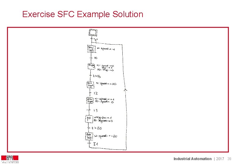
Exercise SFC Example Solution Industrial Automation | 2017 39
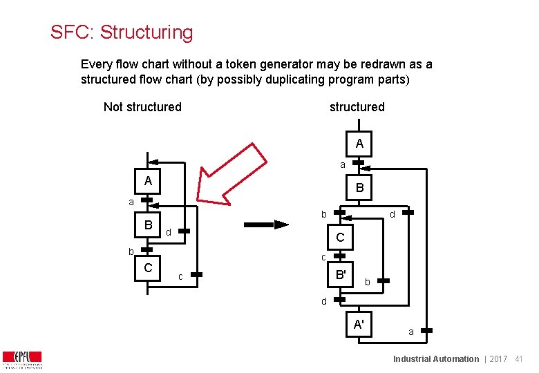
SFC: Structuring Every flow chart without a token generator may be redrawn as a structured flow chart (by possibly duplicating program parts) Not structured A a A B a B b d C b C d c B' c b d A' a Industrial Automation | 2017 41
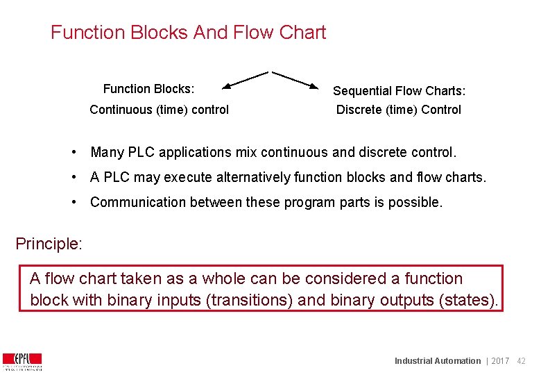
Function Blocks And Flow Chart Function Blocks: Continuous (time) control Sequential Flow Charts: Discrete (time) Control • Many PLC applications mix continuous and discrete control. • A PLC may execute alternatively function blocks and flow charts. • Communication between these program parts is possible. Principle: A flow chart taken as a whole can be considered a function block with binary inputs (transitions) and binary outputs (states). Industrial Automation | 2017 42
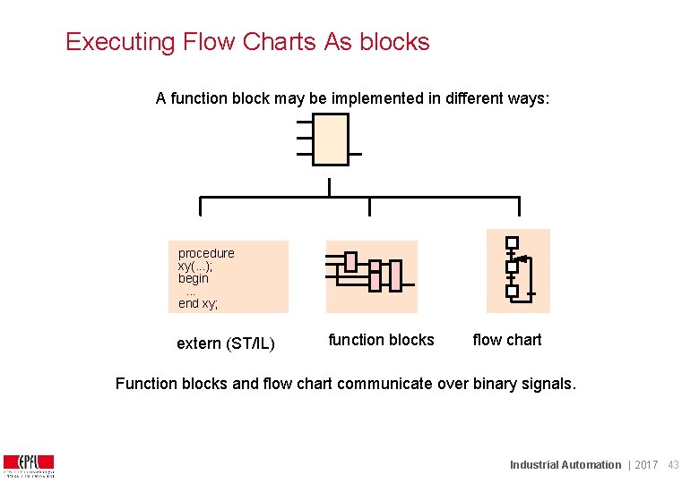
Executing Flow Charts As blocks A function block may be implemented in different ways: procedure xy(. . . ); begin. . . end xy; extern (ST/IL) function blocks flow chart Function blocks and flow chart communicate over binary signals. Industrial Automation | 2017 43
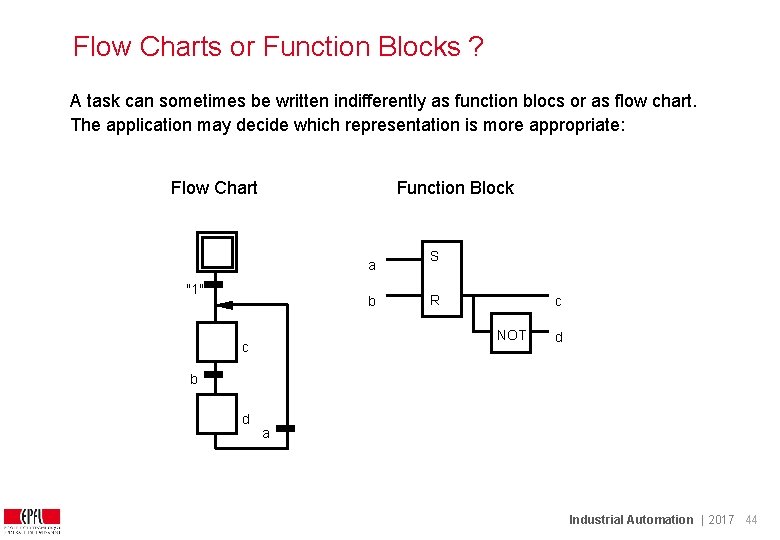
Flow Charts or Function Blocks ? A task can sometimes be written indifferently as function blocs or as flow chart. The application may decide which representation is more appropriate: Flow Chart Function Block a "1" b S R c NOT c d b d a Industrial Automation | 2017 44
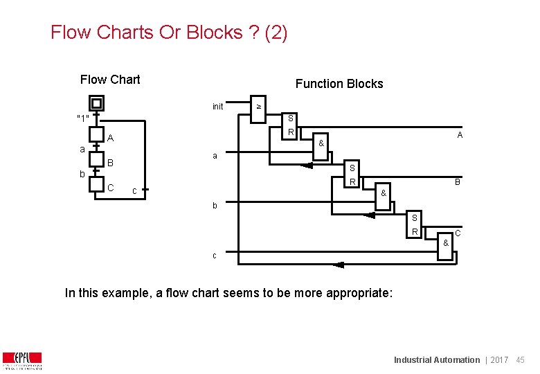
Flow Charts Or Blocks ? (2) Flow Chart Function Blocks init "1" ≥ S R A a a B S b C A & R c B & b S R C & c In this example, a flow chart seems to be more appropriate: Industrial Automation | 2017 45
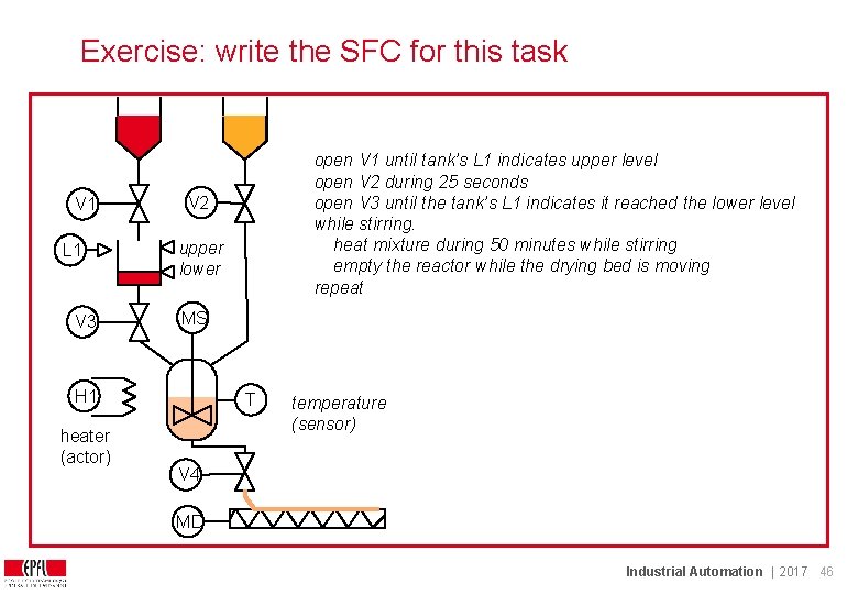
Exercise: write the SFC for this task V 1 L 1 V 3 V 2 upper lower MS H 1 heater (actor) open V 1 until tank’s L 1 indicates upper level open V 2 during 25 seconds open V 3 until the tank’s L 1 indicates it reached the lower level while stirring. heat mixture during 50 minutes while stirring empty the reactor while the drying bed is moving repeat T temperature (sensor) V 4 MD Industrial Automation | 2017 46
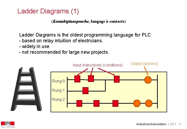
Ladder Diagrams (1) (Kontaktplansprache, langage à contacts) Ladder Diagrams is the oldest programming language for PLC - based on relay intuition of electricians. - widely in use - not recommended for large new projects. Input instructions (conditions) Output (actions) Rung 0 Rung 1 Rung 2 Industrial Automation | 2017 47
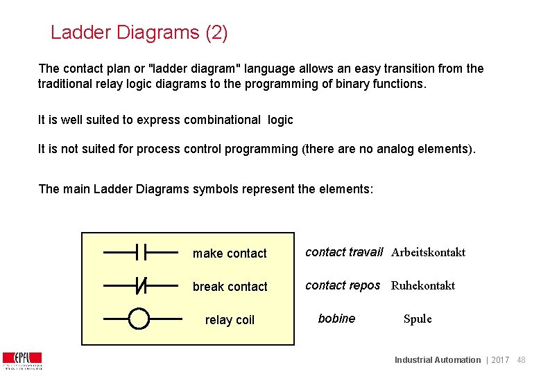
Ladder Diagrams (2) The contact plan or "ladder diagram" language allows an easy transition from the traditional relay logic diagrams to the programming of binary functions. It is well suited to express combinational logic It is not suited for process control programming (there are no analog elements). The main Ladder Diagrams symbols represent the elements: make contact travail Arbeitskontakt break contact repos Ruhekontakt relay coil bobine Spule Industrial Automation | 2017 48
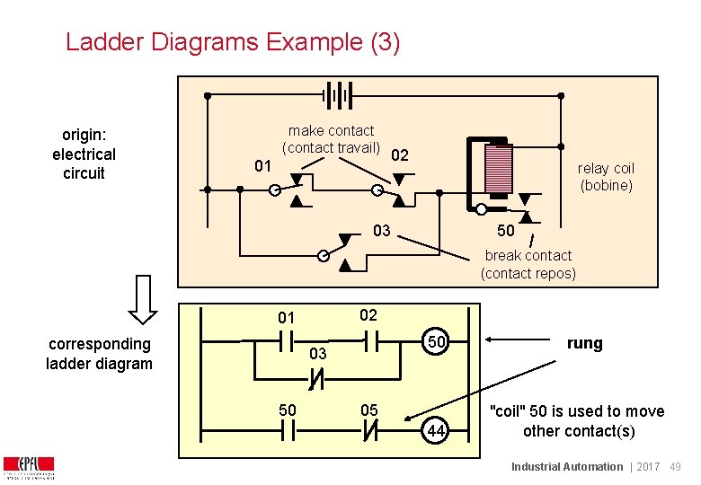
Ladder Diagrams Example (3) origin: electrical circuit make contact (contact travail) 01 02 relay coil (bobine) 03 50 break contact (contact repos) 02 01 corresponding ladder diagram 50 03 50 05 44 rung "coil" 50 is used to move other contact(s) Industrial Automation | 2017 49
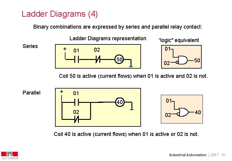
Ladder Diagrams (4) Binary combinations are expressed by series and parallel relay contact: Ladder Diagrams representation Series + 01 “logic" equivalent 01 02 50 Coil 50 is active (current flows) when 01 is active and 02 is not. Parallel + 01 40 02 01 02 40 Coil 40 is active (current flows) when 01 is active or 02 is not. Industrial Automation | 2017 50
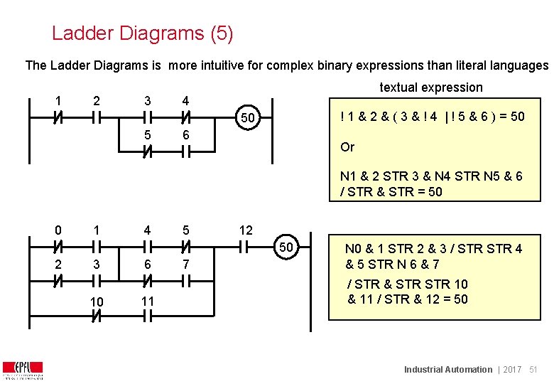
Ladder Diagrams (5) The Ladder Diagrams is more intuitive for complex binary expressions than literal languages 1 2 3 textual expression 4 ! 1 & 2 & ( 3 & ! 4 | ! 5 & 6 ) = 50 50 5 6 Or N 1 & 2 STR 3 & N 4 STR N 5 & 6 / STR & STR = 50 0 1 4 5 12 50 2 3 10 6 11 7 N 0 & 1 STR 2 & 3 / STR 4 & 5 STR N 6 & 7 / STR & STR 10 & 11 / STR & 12 = 50 Industrial Automation | 2017 51
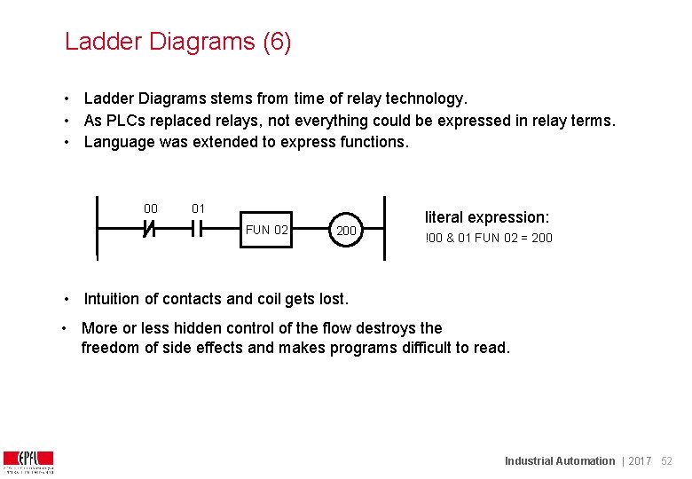
Ladder Diagrams (6) • Ladder Diagrams stems from time of relay technology. • As PLCs replaced relays, not everything could be expressed in relay terms. • Language was extended to express functions. 00 01 FUN 02 200 literal expression: !00 & 01 FUN 02 = 200 • Intuition of contacts and coil gets lost. • More or less hidden control of the flow destroys the freedom of side effects and makes programs difficult to read. Industrial Automation | 2017 52
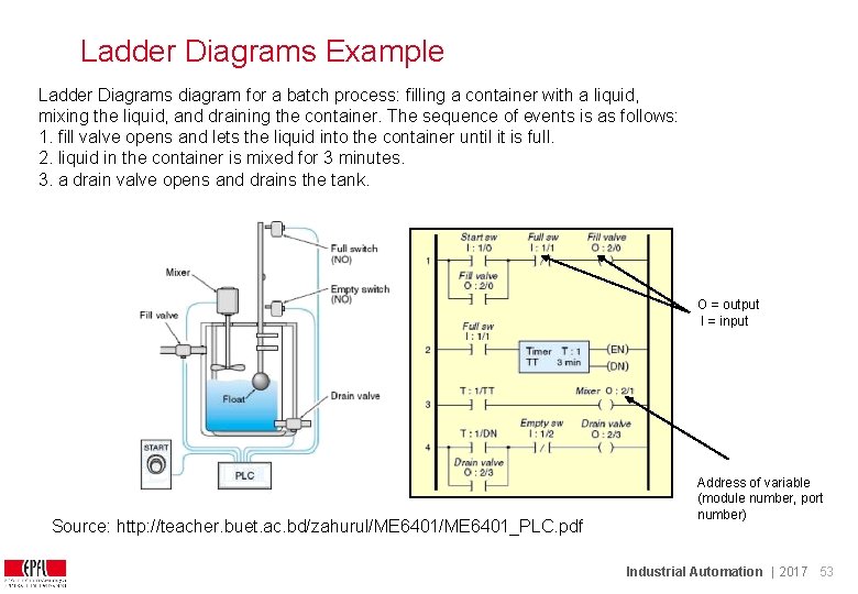
Ladder Diagrams Example Ladder Diagrams diagram for a batch process: filling a container with a liquid, mixing the liquid, and draining the container. The sequence of events is as follows: 1. fill valve opens and lets the liquid into the container until it is full. 2. liquid in the container is mixed for 3 minutes. 3. a drain valve opens and drains the tank. O = output I = input Source: http: //teacher. buet. ac. bd/zahurul/ME 6401_PLC. pdf Address of variable (module number, port number) Industrial Automation | 2017 53
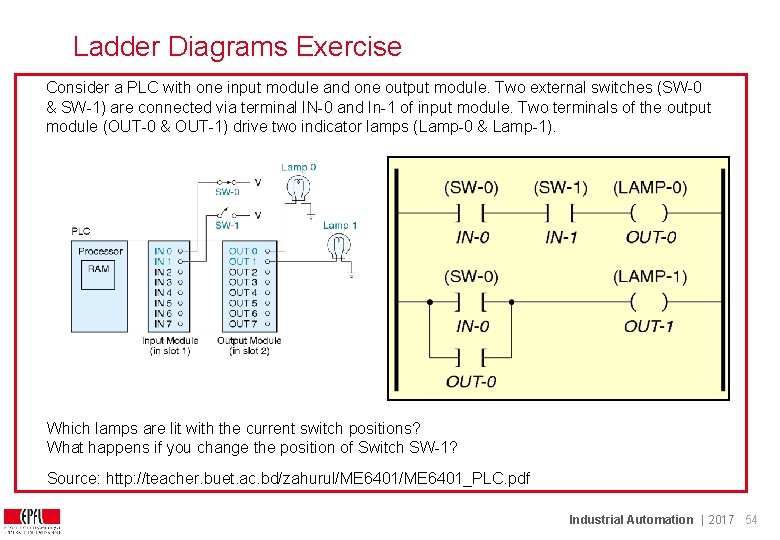
Ladder Diagrams Exercise Consider a PLC with one input module and one output module. Two external switches (SW-0 & SW-1) are connected via terminal IN-0 and In-1 of input module. Two terminals of the output module (OUT-0 & OUT-1) drive two indicator lamps (Lamp-0 & Lamp-1). Which lamps are lit with the current switch positions? What happens if you change the position of Switch SW-1? Source: http: //teacher. buet. ac. bd/zahurul/ME 6401_PLC. pdf Industrial Automation | 2017 54
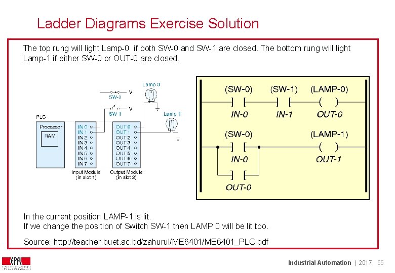
Ladder Diagrams Exercise Solution The top rung will light Lamp-0 if both SW-0 and SW-1 are closed. The bottom rung will light Lamp-1 if either SW-0 or OUT-0 are closed. In the current position LAMP-1 is lit. If we change the position of Switch SW-1 then LAMP 0 will be lit too. Source: http: //teacher. buet. ac. bd/zahurul/ME 6401_PLC. pdf Industrial Automation | 2017 55
Ladder Diagrams (7) Ladder Diagrams provides neither: • sub-programs (blocks), nor • data encapsulation nor • structured data types. Not suited to make reusable modules. IEC 61131 does not prescribe the minimum requirements for a compiler / interpreter such as number of rungs per page nor does it specifies the minimum subset to be implemented. Therefore, it should not be used for large programs made by groups of people It is very limited when considering analog values (it has only counters) → used mostly in manufacturing, not in process control Industrial Automation | 2017 56
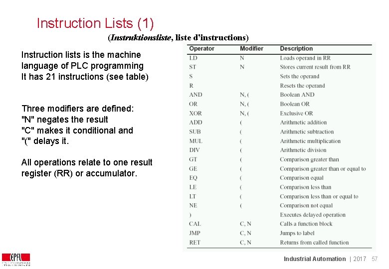
Instruction Lists (1) (Instruktionsliste, liste d'instructions) Instruction lists is the machine language of PLC programming It has 21 instructions (see table) Three modifiers are defined: "N" negates the result "C" makes it conditional and "(" delays it. All operations relate to one result register (RR) or accumulator. Industrial Automation | 2017 57
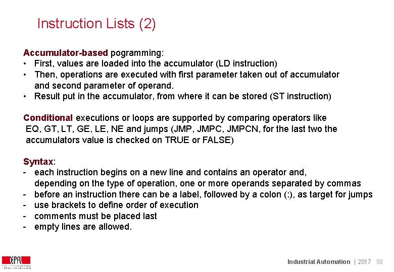
Instruction Lists (2) Accumulator-based pogramming: • First, values are loaded into the accumulator (LD instruction) • Then, operations are executed with first parameter taken out of accumulator and second parameter of operand. • Result put in the accumulator, from where it can be stored (ST instruction) Conditional executions or loops are supported by comparing operators like EQ, GT, LT, GE, LE, NE and jumps (JMP, JMPCN, for the last two the accumulators value is checked on TRUE or FALSE) Syntax: - each instruction begins on a new line and contains an operator and, depending on the type of operation, one or more operands separated by commas - before an instruction there can be a label, followed by a colon (: ), as target for jumps - use brackets to define order of execution - comments must be placed last - empty lines are allowed. Industrial Automation | 2017 58
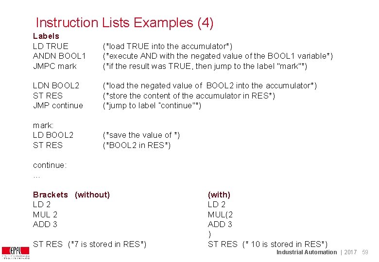
Instruction Lists Examples (4) Labels LD TRUE ANDN BOOL 1 JMPC mark (*load TRUE into the accumulator*) (*execute AND with the negated value of the BOOL 1 variable*) (*if the result was TRUE, then jump to the label "mark"*) LDN BOOL 2 ST RES JMP continue (*load the negated value of BOOL 2 into the accumulator*) (*store the content of the accumulator in RES*) (*jump to label “continue"*) mark: LD BOOL 2 ST RES (*save the value of *) (*BOOL 2 in RES*) continue: … Brackets (without) LD 2 MUL 2 ADD 3 ST RES (*7 is stored in RES*) (with) LD 2 MUL(2 ADD 3 ) ST RES (* 10 is stored in RES*) Industrial Automation | 2017 59
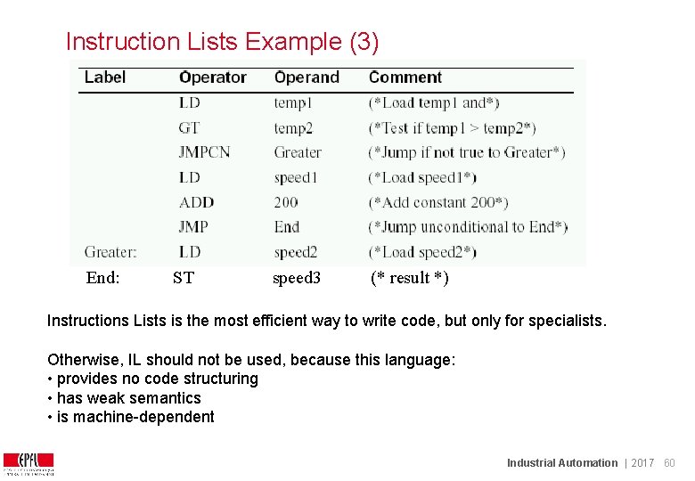
Instruction Lists Example (3) End: ST speed 3 (* result *) Instructions Lists is the most efficient way to write code, but only for specialists. Otherwise, IL should not be used, because this language: • provides no code structuring • has weak semantics • is machine-dependent Industrial Automation | 2017 60
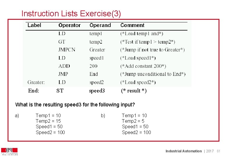
Instruction Lists Exercise(3) End: ST speed 3 (* result *) What is the resulting speed 3 for the following input? a) Temp 1 = 10 Temp 2 = 15 Speed 1 = 50 Speed 2 = 100 b) Temp 1 = 10 Temp 2 = 5 Speed 1 = 50 Speed 2 = 100 Industrial Automation | 2017 61
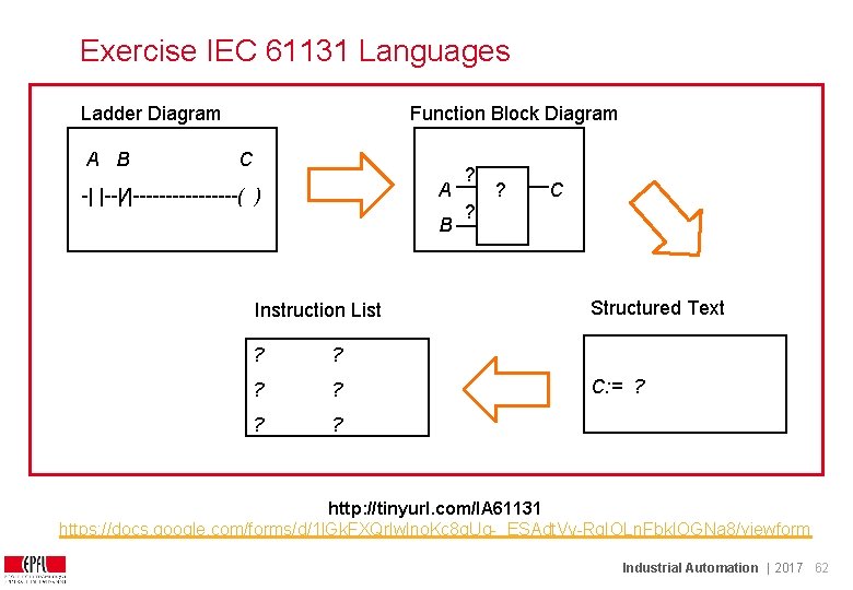
Exercise IEC 61131 Languages Ladder Diagram A B Function Block Diagram C A -| |--|/|--------( ) B Instruction List ? ? C ? Structured Text C: = ? http: //tinyurl. com/IA 61131 https: //docs. google. com/forms/d/1 l. Gk. FXQrlwlno. Kc 8 g. Ug-_ESAdt. Vy-Rg. IOLn. Fbk. IOGNa 8/viewform Industrial Automation | 2017 62
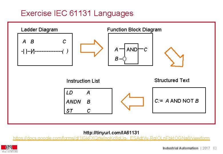
Exercise IEC 61131 Languages Ladder Diagram A B Function Block Diagram C A -| |--|/|--------( ) AND C B Instruction List LD A ANDN B ST C Structured Text C: = A AND NOT B http: //tinyurl. com/IA 61131 https: //docs. google. com/forms/d/1 l. Gk. FXQrlwlno. Kc 8 g. Ug-_ESAdt. Vy-Rg. IOLn. Fbk. IOGNa 8/viewform Industrial Automation | 2017 63
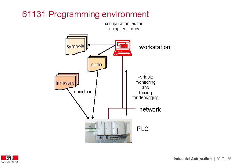
Programming environment capabilities A PLC programming environment (e. g. ABB Control. Builder, Siemens Step 7, Co. De. Sys, . . . ) allows the programmer to - program in one of the IEC 61131 languages - define the variables (name and type) - bind the variables to the input/output (binary, analog) - run simulations - download programs and firmware to the PLC - upload from the PLC (if provided, rare) - monitor the PLC - document and print Industrial Automation | 2017 64
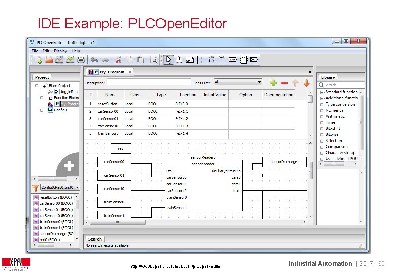
IDE Example: PLCOpen. Editor http: //www. openplcproject. com/plcopen-editor Industrial Automation | 2017 65
61131 Programming environment configuration, editor, compiler, library symbols workstation code firmware download variable monitoring and forcing for debugging network PLC Industrial Automation | 2017 66
Is IEC 61131 FB an object-oriented language ? Not really: it does not support inheritance. Blocks are not recursive. But it supports interface definition (typed signals), instantiation, encapsulation, some form of polymorphism. Some programming environments offer “control modules” for better object-orientation Industrial Automation | 2017 67
Limitations of IEC 61131 - No support to distribute execution of programs over several devices - No support for event-driven operation. Blocks may be triggered by a Boolean variable (intentionally, for good reasons). - If structured text increases in importance, better constructs are required (object-orientation) Industrial Automation | 2017 68
Assessment Which are programming languages defined in IEC 61131 and for what are they used ? In a function block language, which are the two elements of programming ? How is a PLC program executed and why is it that way ? Draw a ladder diagram and the corresponding function block chart. Draw a sequential chart implementing a 2 -bit counter. Program a saw tooth waveform generator with function blocks. How are inputs and outputs to the process treated in a function block language ? Write a program for a simple chewing-gum coin machine. Program a ramp generator for a ventilator speed control (soft start and stop in 5 s) Industrial Automation | 2017 69