
MODULE D 2 CELLULAR NETWORKS mobnet epfl ch
MODULE D 2 – CELLULAR NETWORKS mobnet. epfl. ch Some of the slides are adapted from Stallings, Wireless Communications & Networks, Second Edition, Chapter 10 © 2005 Pearson Education, Inc. All rights reserved. 0 -13 -191835 -4 Some of the content is inspired by Rappaport, Wireless Communications, Second Edition, Chapters 3 and 9, 2002 1
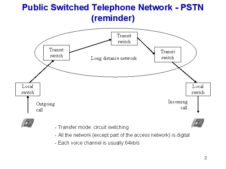
Public Switched Telephone Network - PSTN (reminder) Transit switch Long distance network Transit switch Local switch Outgoing call Incoming call - Transfer mode: circuit switching - All the network (except part of the access network) is digital - Each voice channel is usually 64 kb/s 2
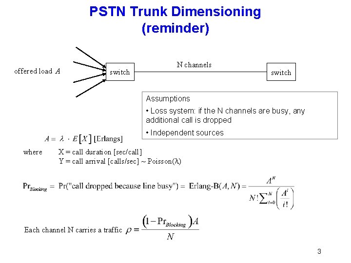
PSTN Trunk Dimensioning (reminder) offered load A switch N channels switch Assumptions • Loss system: if the N channels are busy, any additional call is dropped • Independent sources where X = call duration [sec/call] Y = call arrival [calls/sec] ~ Poisson( ) Each channel N carries a traffic 3
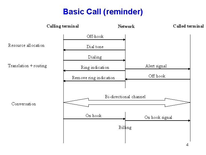
Basic Call (reminder) Calling terminal Called terminal Network Off-hook Resource allocation Dial tone Dialing Translation + routing Alert signal Ring indication Off hook Remove ring indication Bi-directional channel Conversation On hook signal Billing 4
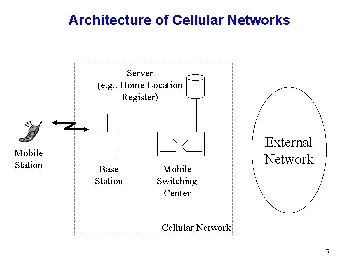
Architecture of Cellular Networks Server (e. g. , Home Location Register) Mobile Station Base Station Mobile Switching Center External Network Cellular Network 5
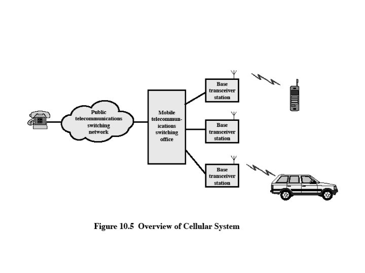
6
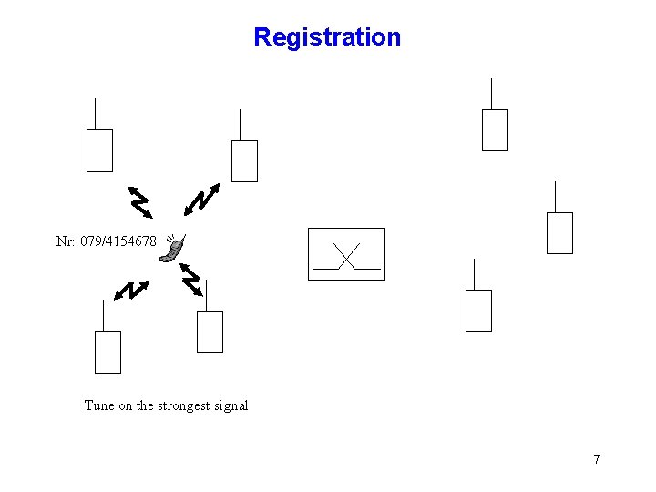
Registration Nr: 079/4154678 Tune on the strongest signal 7
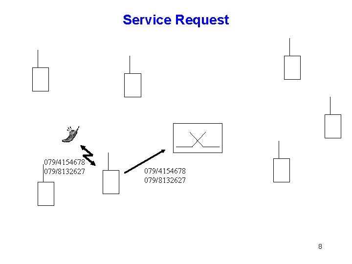
Service Request 079/4154678 079/8132627 8
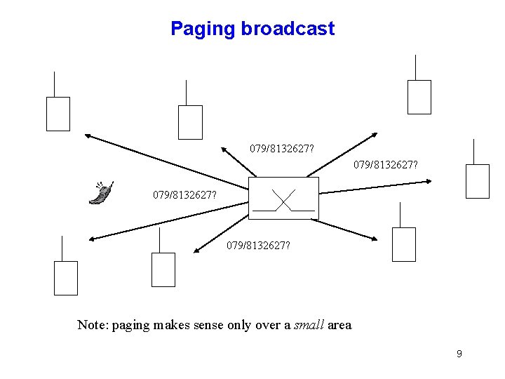
Paging broadcast 079/8132627? Note: paging makes sense only over a small area 9
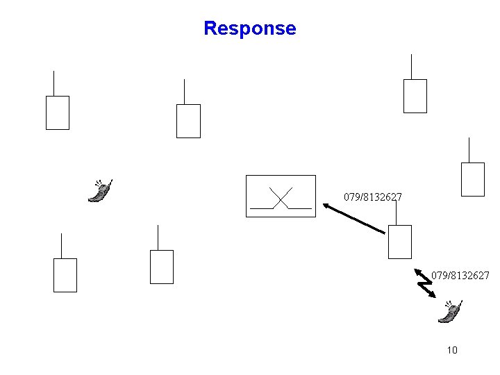
Response 079/8132627 10
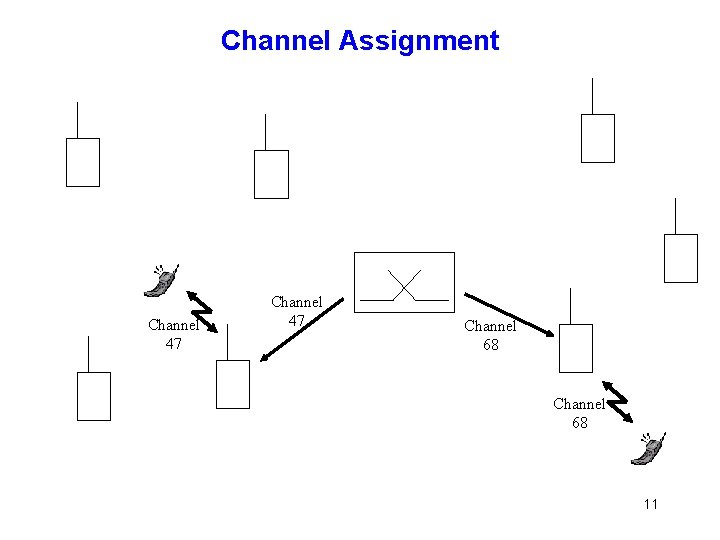
Channel Assignment Channel 47 Channel 68 11
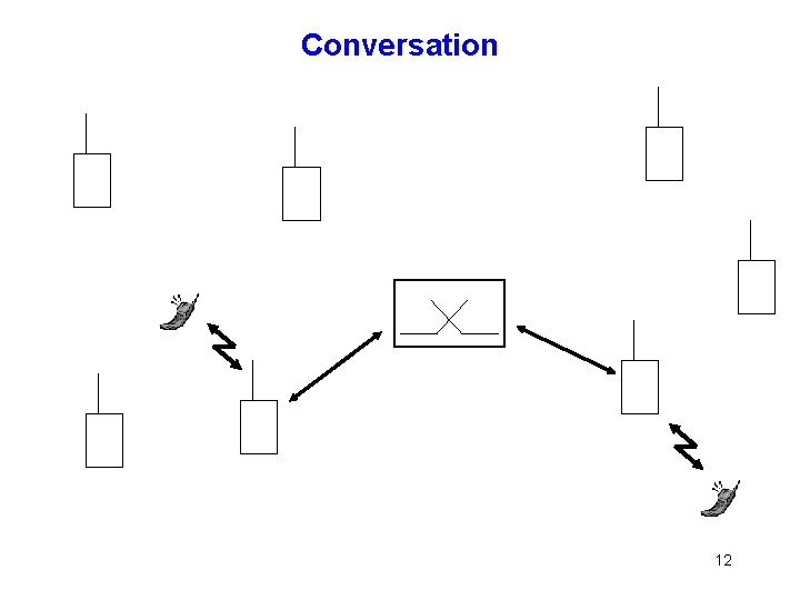
Conversation 12
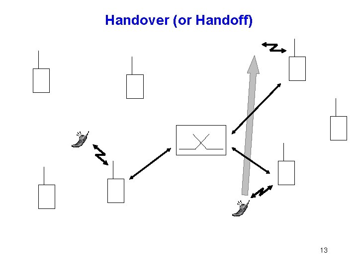
Handover (or Handoff) 13
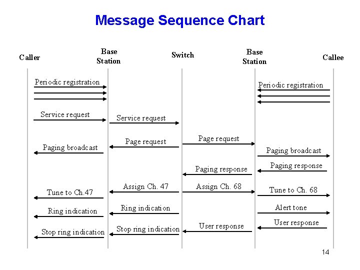
Message Sequence Chart Base Station Caller Base Station Switch Periodic registration Service request Paging broadcast Tune to Ch. 47 Ring indication Stop ring indication Callee Periodic registration Service request Page request Paging broadcast Assign Ch. 47 Paging response Assign Ch. 68 Tune to Ch. 68 Alert tone Ring indication Stop ring indication User response 14
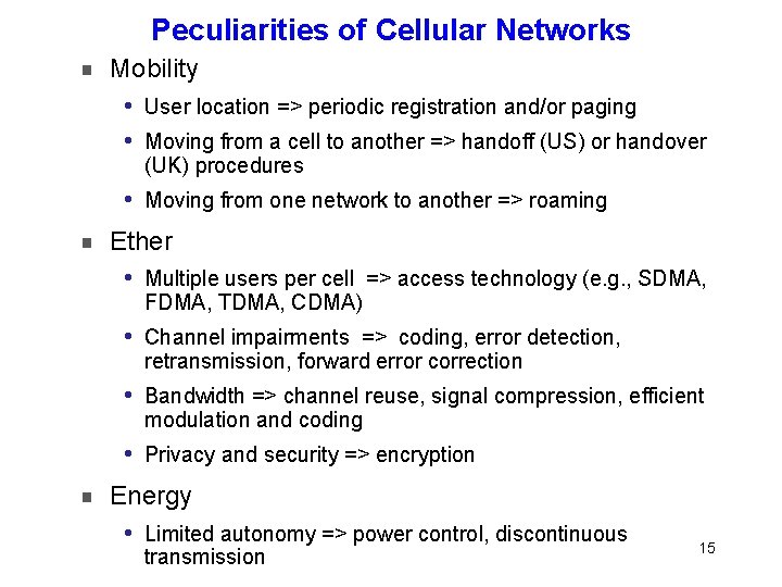
Peculiarities of Cellular Networks Mobility i User location => periodic registration and/or paging i Moving from a cell to another => handoff (US) or handover (UK) procedures i Moving from one network to another => roaming Ether i Multiple users per cell => access technology (e. g. , SDMA, FDMA, TDMA, CDMA) i Channel impairments => coding, error detection, retransmission, forward error correction i Bandwidth => channel reuse, signal compression, efficient modulation and coding i Privacy and security => encryption Energy i Limited autonomy => power control, discontinuous transmission 15
Offered Services Telephony services (i. e. , voice mail, call transfer, …) Short Message Services (SMS) Packet switched data (e. g. , GPRS, EDGE, HSDPA, LTE), notably for Web access Location-based services Application store (App. Store of Apple, Application Market of Android, . . . ) Entertainment (music, video, …); Mobile TV Mobile extension of online social networks (Facebook Mobile, …) Friend location (Foursquare, Google Latitude, Localiser. Mes. Amis, …) Peer-to-peer wireless services (e. g. , over Bluetooth and Wi. Fi in ad hoc mode); 16
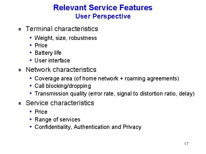
Relevant Service Features User Perspective Terminal characteristics Weight, size, robustness i Price i Battery life i User interface i Network characteristics Coverage area (of home network + roaming agreements) i Call blocking/dropping i Transmission quality (error rate, signal to distortion ratio, delay) i Service characteristics Price i Range of services i Confidentiality, Authentication and Privacy i 17
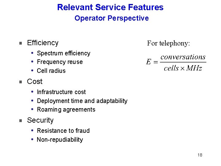
Relevant Service Features Operator Perspective Efficiency For telephony: Spectrum efficiency i Frequency reuse i Cell radius i Cost Infrastructure cost i Deployment time and adaptability i Roaming agreements i Security Resistance to fraud i Non-repudiability i 18
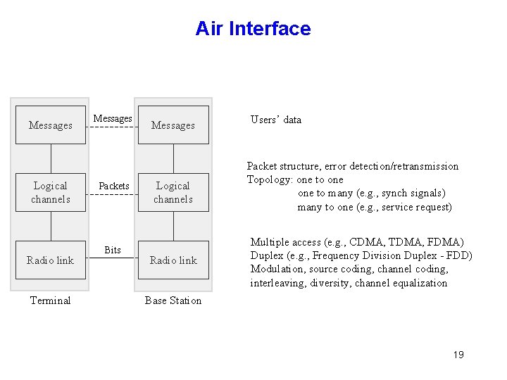
Air Interface Messages Logical channels Radio link Terminal Messages Packets Bits Messages Logical channels Radio link Users’ data Packet structure, error detection/retransmission Topology: one to many (e. g. , synch signals) many to one (e. g. , service request) Multiple access (e. g. , CDMA, TDMA, FDMA) Duplex (e. g. , Frequency Division Duplex - FDD) Modulation, source coding, channel coding, interleaving, diversity, channel equalization Base Station 19
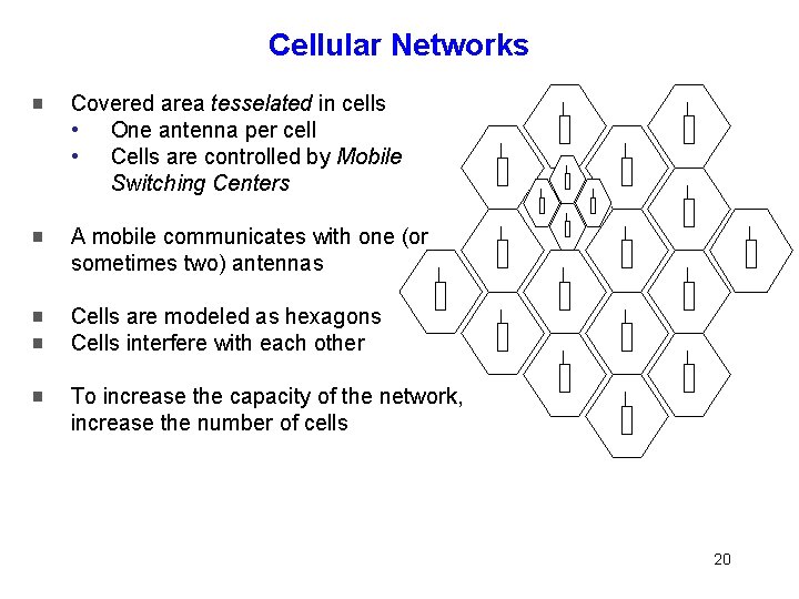
Cellular Networks Covered area tesselated in cells • One antenna per cell • Cells are controlled by Mobile Switching Centers A mobile communicates with one (or sometimes two) antennas Cells are modeled as hexagons Cells interfere with each other To increase the capacity of the network, increase the number of cells 20
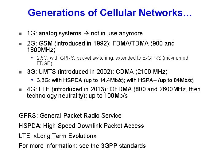
Generations of Cellular Networks… 1 G: analog systems not in use anymore 2 G: GSM (introduced in 1992): FDMA/TDMA (900 and 1800 MHz) i 3 G: UMTS (introduced in 2002): CDMA (2100 MHz) i 2. 5 G: with GPRS: packet switching, extended to E-GPRS (nicknamed EDGE) 3. 5 G: with HSPDA (up to 14. 4 Mb/s); with HSPA+ (up to 84 Mb/s) 4 G: LTE (introduced in 2013): OFDMA (800 and 2600 MHz, then technology neutrality); up to 100 Mb/s GPRS: General Packet Radio Service HSPDA: High Speed Downlink Packet Access LTE: «Long Term Evolution» For more information: see the 3 GPP standards
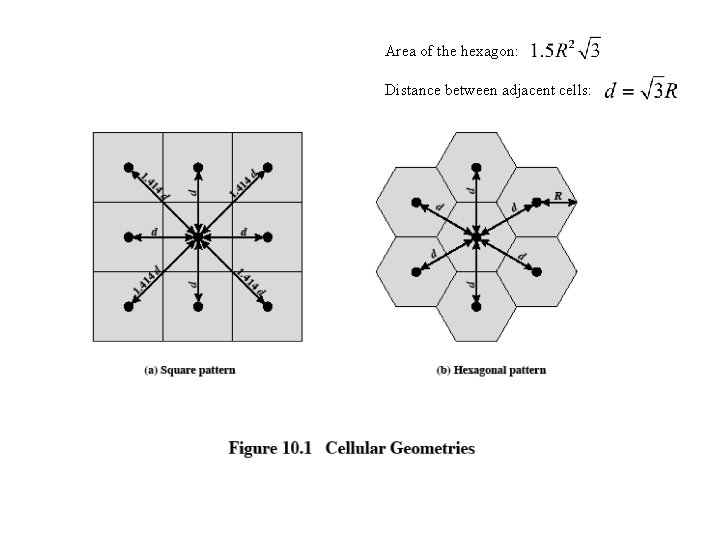
Area of the hexagon: Distance between adjacent cells: 22
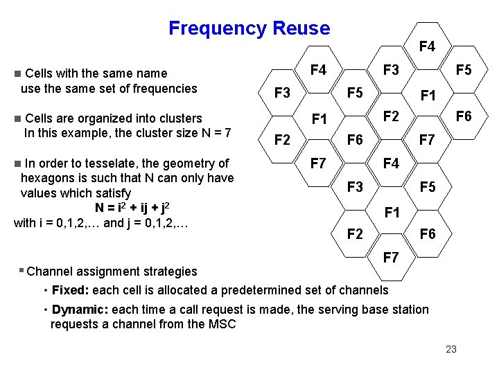
Frequency Reuse Cells with the same name use the same set of frequencies F 4 Cells are organized into clusters In this example, the cluster size N = 7 In order to tesselate, the geometry of hexagons is such that N can only have values which satisfy N = i 2 + ij + j 2 with i = 0, 1, 2, … and j = 0, 1, 2, … Channel assignment strategies F 4 F 3 F 5 F 1 F 2 F 5 F 6 F 7 F 4 F 3 F 5 F 1 F 2 F 6 F 7 • Fixed: each cell is allocated a predetermined set of channels • Dynamic: each time a call request is made, the serving base station requests a channel from the MSC 23
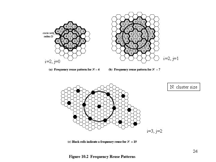
i=2, j=1 i=2, j=0 N: cluster size i=3, j=2 24
25
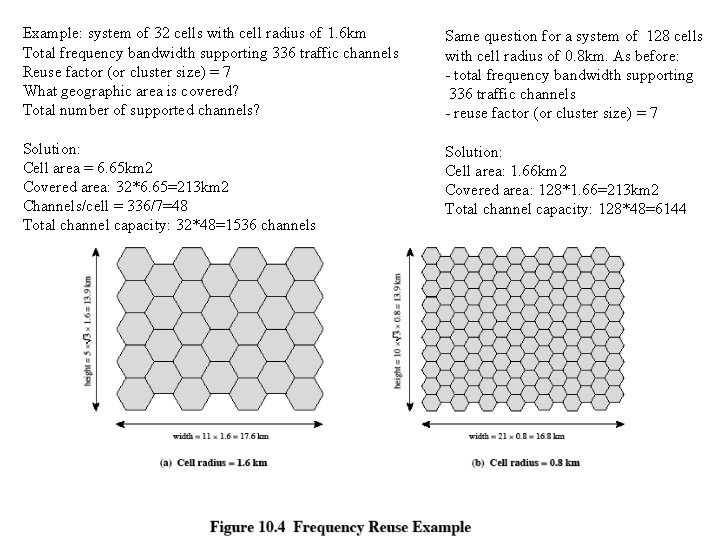
Example: system of 32 cells with cell radius of 1. 6 km Total frequency bandwidth supporting 336 traffic channels Reuse factor (or cluster size) = 7 What geographic area is covered? Total number of supported channels? Same question for a system of 128 cells with cell radius of 0. 8 km. As before: - total frequency bandwidth supporting 336 traffic channels - reuse factor (or cluster size) = 7 Solution: Cell area = 6. 65 km 2 Covered area: 32*6. 65=213 km 2 Channels/cell = 336/7=48 Total channel capacity: 32*48=1536 channels Solution: Cell area: 1. 66 km 2 Covered area: 128*1. 66=213 km 2 Total channel capacity: 128*48=6144 26
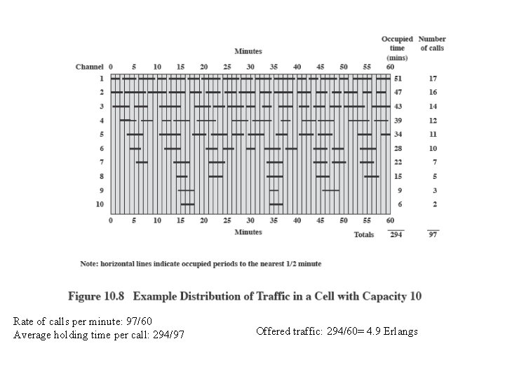
Rate of calls per minute: 97/60 Average holding time per call: 294/97 Offered traffic: 294/60= 4. 9 Erlangs 27
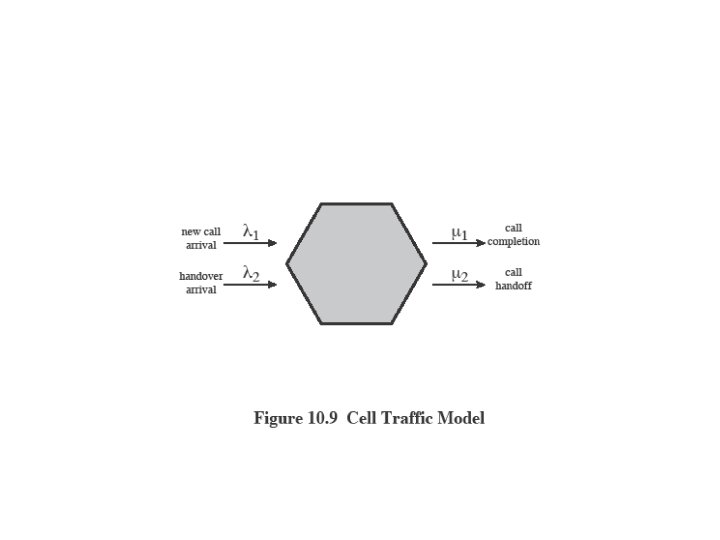
28
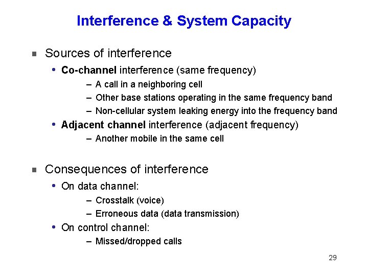
Interference & System Capacity Sources of interference i Co-channel interference (same frequency) – A call in a neighboring cell – Other base stations operating in the same frequency band – Non-cellular system leaking energy into the frequency band i Adjacent channel interference (adjacent frequency) – Another mobile in the same cell Consequences of interference i On data channel: – Crosstalk (voice) – Erroneous data (data transmission) i On control channel: – Missed/dropped calls 29
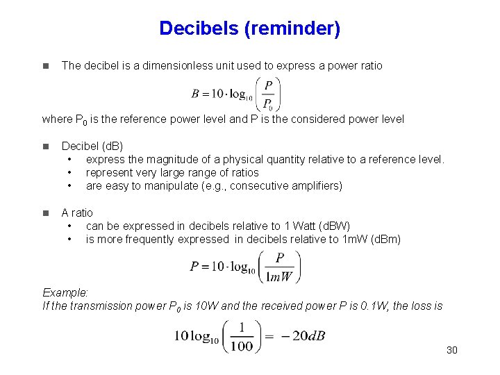
Decibels (reminder) The decibel is a dimensionless unit used to express a power ratio where P 0 is the reference power level and P is the considered power level Decibel (d. B) • express the magnitude of a physical quantity relative to a reference level. • represent very large range of ratios • are easy to manipulate (e. g. , consecutive amplifiers) A ratio • can be expressed in decibels relative to 1 Watt (d. BW) • is more frequently expressed in decibels relative to 1 m. W (d. Bm) Example: If the transmission power P 0 is 10 W and the received power P is 0. 1 W, the loss is 30
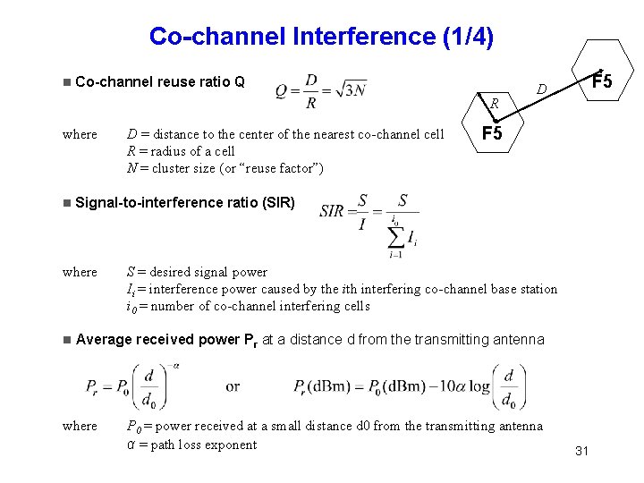
Co-channel Interference (1/4) Co-channel reuse ratio Q R where F 5 Signal-to-interference ratio (SIR) where D = distance to the center of the nearest co-channel cell R = radius of a cell N = cluster size (or “reuse factor”) F 5 D S = desired signal power Ii = interference power caused by the ith interfering co-channel base station i 0 = number of co-channel interfering cells Average received power Pr at a distance d from the transmitting antenna where P 0 = power received at a small distance d 0 from the transmitting antenna α = path loss exponent 31
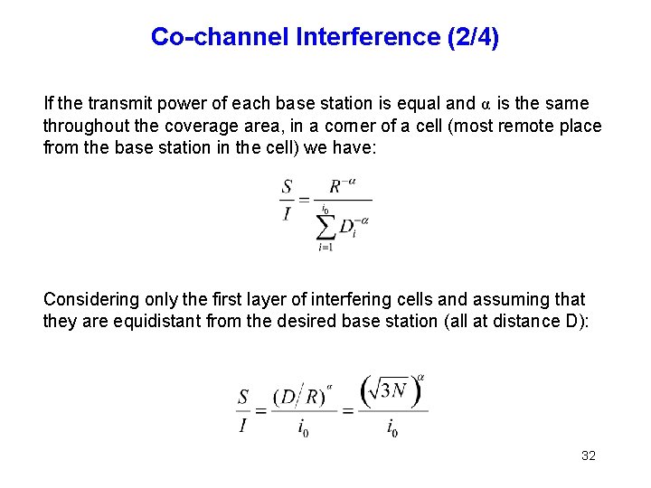
Co-channel Interference (2/4) If the transmit power of each base station is equal and α is the same throughout the coverage area, in a corner of a cell (most remote place from the base station in the cell) we have: Considering only the first layer of interfering cells and assuming that they are equidistant from the desired base station (all at distance D): 32
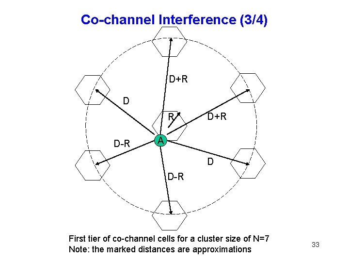
Co-channel Interference (3/4) D+R D R D-R D+R A D D-R First tier of co-channel cells for a cluster size of N=7 Note: the marked distances are approximations 33
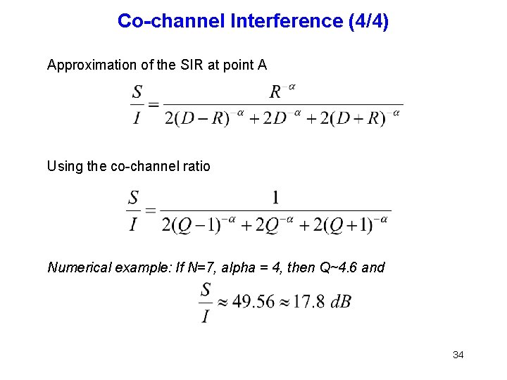
Co-channel Interference (4/4) Approximation of the SIR at point A Using the co-channel ratio Numerical example: If N=7, alpha = 4, then Q~4. 6 and 34
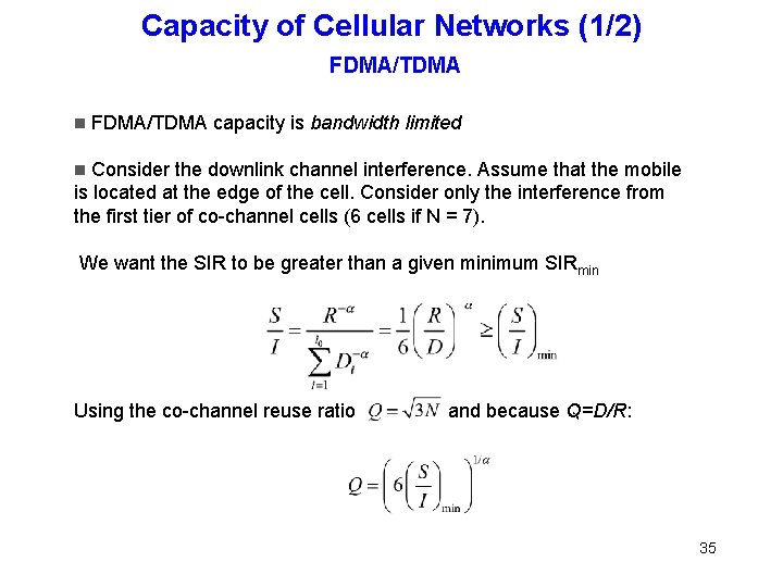
Capacity of Cellular Networks (1/2) FDMA/TDMA capacity is bandwidth limited Consider the downlink channel interference. Assume that the mobile is located at the edge of the cell. Consider only the interference from the first tier of co-channel cells (6 cells if N = 7). We want the SIR to be greater than a given minimum SIRmin Using the co-channel reuse ratio and because Q=D/R: 35
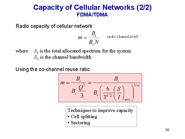
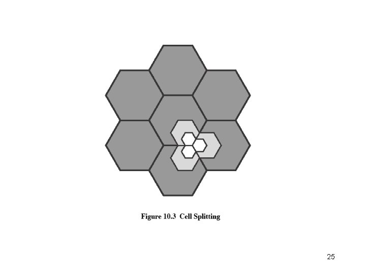
Capacity of Cellular Networks (2/2) FDMA/TDMA Radio capacity of cellular network radio channels/cell where Bt is the total allocated spectrum for the system Bc is the channel bandwidth Using the co-channel reuse ratio Techniques to improve capacity • Cell splitting • Sectoring 36
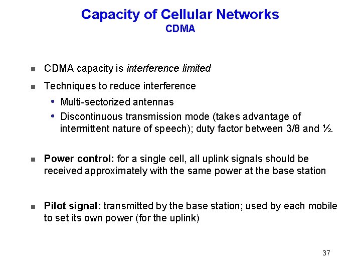
Capacity of Cellular Networks CDMA capacity is interference limited Techniques to reduce interference Multi-sectorized antennas i Discontinuous transmission mode (takes advantage of intermittent nature of speech); duty factor between 3/8 and ½. i Power control: for a single cell, all uplink signals should be received approximately with the same power at the base station Pilot signal: transmitted by the base station; used by each mobile to set its own power (for the uplink) 37
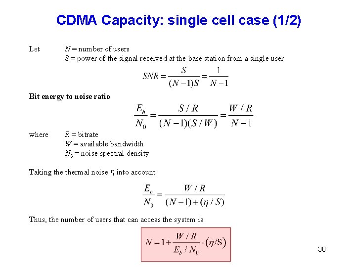
CDMA Capacity: single cell case (1/2) Let N = number of users S = power of the signal received at the base station from a single user Bit energy to noise ratio where R = bitrate W = available bandwidth N 0 = noise spectral density Taking thermal noise η into account Thus, the number of users that can access the system is 38
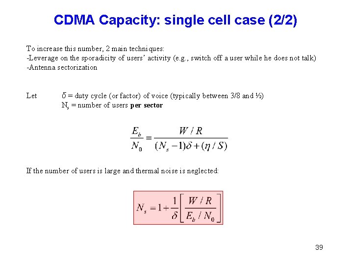
CDMA Capacity: single cell case (2/2) To increase this number, 2 main techniques: -Leverage on the sporadicity of users’ activity (e. g. , switch off a user while he does not talk) -Antenna sectorization Let δ = duty cycle (or factor) of voice (typically between 3/8 and ½) Ns = number of users per sector If the number of users is large and thermal noise is neglected: 39
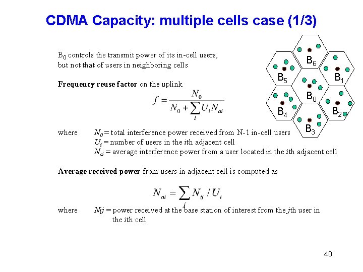
CDMA Capacity: multiple cells case (1/3) B 0 controls the transmit power of its in-cell users, but not that of users in neighboring cells Frequency reuse factor on the uplink B 6 B 5 B 1 B 0 B 4 where B 2 B 3 N 0 = total interference power received from N-1 in-cell users Ui = number of users in the ith adjacent cell Nai = average interference power from a user located in the ith adjacent cell Average received power from users in adjacent cell is computed as where Nij = power received at the base station of interest from the jth user in the ith cell 40
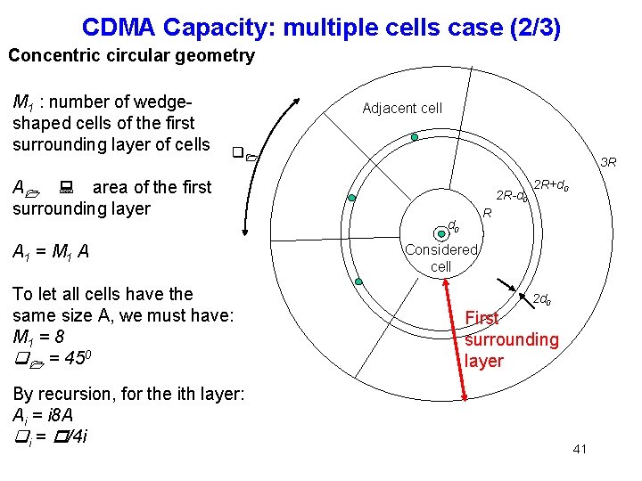
CDMA Capacity: multiple cells case (2/3) Concentric circular geometry M 1 : number of wedgeshaped cells of the first surrounding layer of cells Adjacent cell q 1 A 1 : area of the first surrounding layer A 1 = M 1 A To let all cells have the same size A, we must have: M 1 = 8 q 1 = 450 By recursion, for the ith layer: Ai = i 8 A qi = p/4 i 3 R 2 R-d 0 2 R+d 0 R d 0 Considered cell 2 d 0 First surrounding layer 41
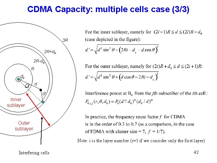
CDMA Capacity: multiple cells case (3/3) 3 R 2 R+d 0 2 R-d 0 R d 0 q d d’ Inner sublayer Outer sublayer Note: i is the layer number (i=1 if we consider only the first layer) Interfering cells 42
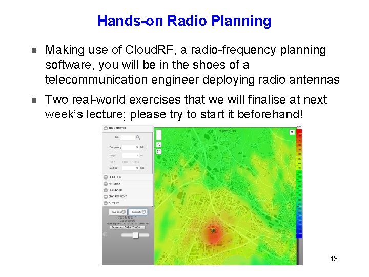
Hands-on Radio Planning Making use of Cloud. RF, a radio-frequency planning software, you will be in the shoes of a telecommunication engineer deploying radio antennas Two real-world exercises that we will finalise at next week’s lecture; please try to start it beforehand! 43
Hands-on Radio Planning 1. 2. 3. 4. 5. Tasks to be completed before April 1 st: Create a personal account: http: //cloudrf. com/account/register Sign in with your personal account: http: //cloudrf. com/account/login Order a free Region 1 Amateur plan: http: //cloudrf. com/collections/plans/products/itu-1 -amateur-planfor-europe-africa-middle-east-and-russia Start playing with the software using the Web interface: https: //web. cloudrf. com/web/ Do the exercises mentioned in the homework called HW-D 2 -Cloud. RF For any problem, please contact Mathias Humbert: mathias. humbert@epfl. ch 44
Conclusion In this Module D 2, we have addressed essentially network capacity and planning Cellular networks: many base stations Capacity can be increased notably by cell splitting and cell sectoring Reminder: Division multiple access used in cellular network generations (all with SDMA, of course): 2 G: GSM: FDMA/TDMA i 3 G: UMTS: CDMA i 4 G: LTE: OFDMA (Orthogonal Frequency-Division Multiple Access) for the downlink and SC-FDMA (Single-carrier Frequency Division Multiple Access) for the uplink i 45
References Agrawal & Zeng: Chapter 5 T. Rappaport: Wireless Communications, 2 nd edition, Prentice Hall, 2001 M. Schwartz: Mobile Wireless Communications, Cambridge University Press, 2005 W. Stallings: Wireless Communications and Networks, 2 nd edition, Prentice Hall, 2005, Chapter 10 Schiller, Chapter 4 3 GPP and LTE specifications – www. 3 gpp. org (even more difficult to navigate than IETF specifications!) 46

47
- Slides: 47