
Sci Fi BGV Guido Haefeli EPFL 12 6
Sci. Fi BGV Guido Haefeli, EPFL, 12. 6. 2013
Outline �LPHE (EPFL group) at LHCb �Fiber tracker for LHCb Upgrade �Fiber tracker how it works �BGV Sci. Fi modules 2
3
4
5
6
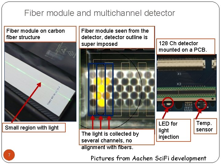
Fiber module and multichannel detector Fiber module on carbon fiber structure Fiber module seen from the detector, detector outline is super imposed Small region with light The light is collected by several channels, no alignment with fibers. 7 128 Ch detector mounted on a PCB. LED for light injection Temp. sensor Pictures from Aachen Sci. Fi development
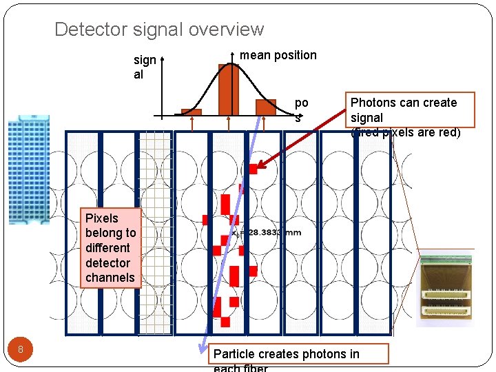
Detector signal overview sign al mean position po s Photons can create signal (fired pixels are red) Pixels belong to different detector channels 8 Particle creates photons in
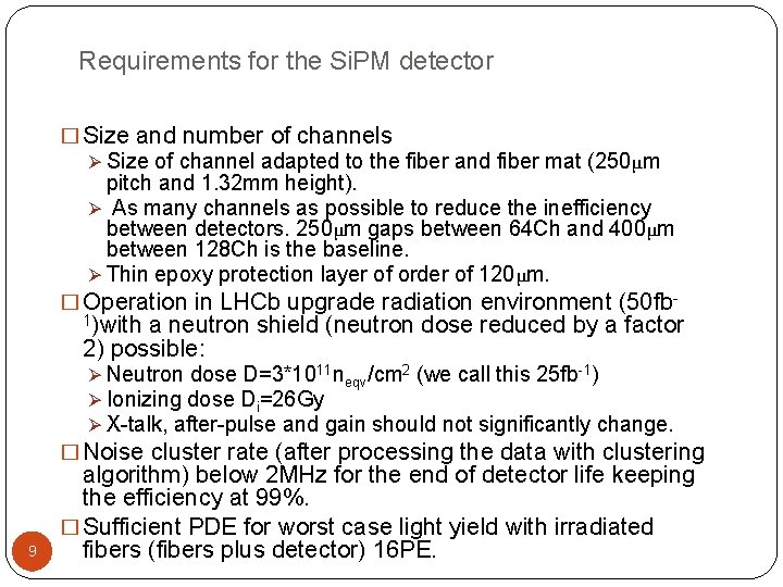
Requirements for the Si. PM detector � Size and number of channels Ø Size of channel adapted to the fiber and fiber mat (250μm pitch and 1. 32 mm height). Ø As many channels as possible to reduce the inefficiency between detectors. 250μm gaps between 64 Ch and 400μm between 128 Ch is the baseline. Ø Thin epoxy protection layer of order of 120μm. � Operation in LHCb upgrade radiation environment (50 fb 1)with a neutron shield (neutron dose reduced by a factor 2) possible: Ø Neutron dose D=3*1011 neqv/cm 2 (we call this 25 fb-1) Ø Ionizing dose Di=26 Gy Ø X-talk, after-pulse and gain should not significantly change. � Noise cluster rate (after processing the data with clustering 9 algorithm) below 2 MHz for the end of detector life keeping the efficiency at 99%. � Sufficient PDE for worst case light yield with irradiated fibers (fibers plus detector) 16 PE.
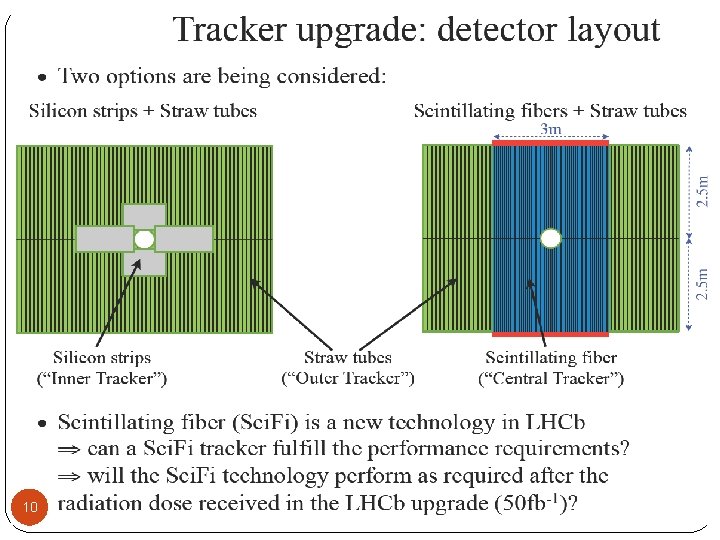
10
Why using a fiber tracker in BGV � Many short fiber tracker modules have been produced by Aachen during the last 3 years. Good quality and fast production possible. � Short fiber modules have enough light, good resolution and are robust. � Radiation environment in BGV is quite low (smaller than 1 k. Gy) at 20 cm distance (right)? Major difficulties compared to LHCb Sci. Fi are not present (radiation and low signal due to fiber irradiation). � Large synergy between BGV and LHCb Upgrade R&D. �Same readout electronics �Same detectors 11 �Gaining experience for operation in radiation environment.
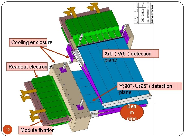
Cooling enclosure X(0°) V(5°) detection plane Readout electronics Y(90°) U(95°) detection plane Bea m pipe 12 Module fixation
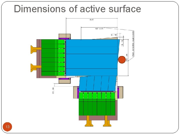
Dimensions of active surface 13
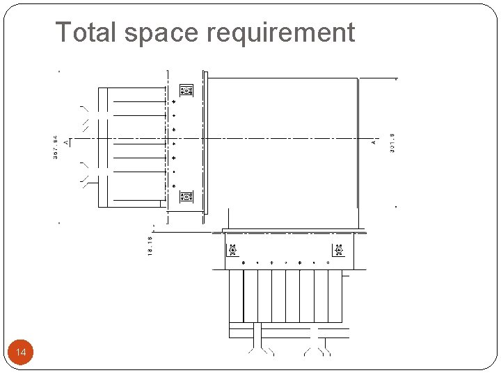
Total space requirement 14
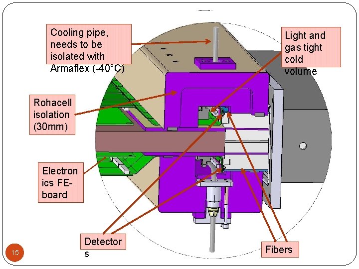
Cooling pipe, needs to be isolated with Armaflex (-40°C) Light and gas tight cold volume Rohacell isolation (30 mm) Electron ics FEboard 15 Detector s Fibers
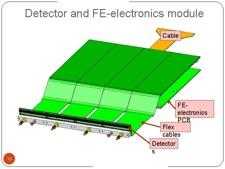
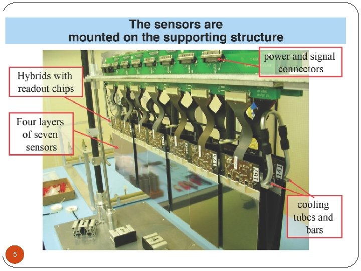
Detector and FE-electronics module Cable FEelectronics PCB Flex cables Detector s 16
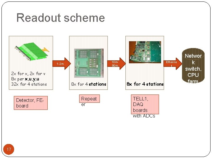
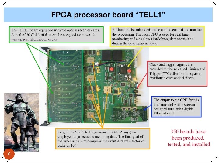
Readout scheme 10 m 60 m 1 -2 m 17 Etherne t 2 x for x, 2 x for v 8 x per x, u, y, u 32 x for 4 stations 8 x for 4 stations Detector, FEboard Repeat er TELL 1, DAQ boards with ADCs Networ k switch, CPU farm
18
- Slides: 18