EET 206 ELECTRIC CIRCUIT II DR SAMILA MAT

 • Chapter 2")
 CO 1: • Ability to explain and analyse special types of")


")

")

")

 • Applying KVL • Coil 1 • Coil 2")
 • Applying KVL • Coil 1 • Coil 2")


 network. • If T")

 network. • Equating terms in")


, (k=1) lossless (R 1=R 2=0) transformer in")


- Slides: 61
EET 206 ELECTRIC CIRCUIT II DR SAMILA MAT ZALI DR FIJAY FAUZI 1
COURSE OUTLINE • Chapter 1 : Mutual inductance (Week 1 -2) • Chapter 2 : Laplace transform (Week 3 -5) • Chapter 3 : Frequency response in AC circuit (Week 6 -8) • Chapter 4 : Fourier series (Week 9 -10) • Chapter 5 : Fourier transform (Week 11 -12) • Chapter 6 : Two port network (Week 13 -14) 2
COURSE OUTCOME (CO) CO 1: • Ability to explain and analyse special types of circuit such as mutual inductance and two port networks. CO 2: • Ability to analyse electric circuits using Laplace Transform, Fourier Series and Fourier Transform for the circuit comprising passive elements. CO 3: • Ability to analyse the concepts of frequency response for AC circuits and construct Bode plot for various types of transfer function. 3
COURSE ASSESSMENT 1. COURSEWORK • -Assignment 1 & 2 • -Quiz 10% 30% 2. MIDTERM EXAM 20% 3. FINAL EXAM 50% 4
CHAPTER 1 OUTLINE • INTRODUCTION OF TRANSFORMER • MUTUAL INDUCTANCE • ENERGY IN A COUPLED CIRCUIT • LINEAR TRANSFORMERS • IDEAL TRANSFORMERS 5
INTRODUCTION OF TRANSFORMER An electrical device designed on the basis of the concept of magnetic coupling. Transfer energy from one circuit to another circuit using magnetically coupled coils. Known as key circuit elements in power systems for stepping up or stepping down AC voltages or current; in electronic circuits as impedance matching , and isolating one part of the circuit from another. 6
MUTUAL INDUCTANCE Ability of one inductor to induce a voltage across another inductor when two inductors are in close to each other. The magnetic flux caused by current in one coil links with the other coil. Faraday’s law – the voltage v induced in the coil is proportional to the number of turns N and the time rate of change of the magnetic flux 7
• Flux, is produce by current, i; changes in is caused by a change in i. • Know as self inductance because relates the voltage induced in a coil by a timevarying current in the same coil. 8
Self Inductance • Definition: Inductance that relates the induced voltage in a coil with a time-varying current in the same coil. • The reason why L is called “Self” Inductance is because the Inductance is the result of its own current (current flowing through its own coil).
• Entire flux 1 links coil 1, the voltage induced in coil 1 is: Self inductance of coil 1 • Only 12 links coil 2, so the voltage induced in coil 2 is: Mutual inductance of coil 2 with respect to coil 1 EET 102 ELECTRIC CIRCUIT II • The open circuit mutual voltage across coil 2. • Magnetic flux 1 emanating from coil 1 has two components: 10
• Entire flux 2 links coil 1, the voltage induced in coil 1 is: Self inductance of coil 2 • Only 21 links coil 2, so the voltage induced in coil 2 is: Mutual inductance of coil 1 with respect to coil 2 EET 102 ELECTRIC CIRCUIT II • The open circuit mutual voltage across coil 1. • Magnetic flux 2 emanating from coil 1 has two components: 11
M is refer as mutual inductance between the two coils. • Mutual coupling exists when inductors or coils are in close proximity and circuit are driven by time-varying sources. • Mutual inductance is the ability of one inductor to induce voltage across a neighboring inductor, measured in henrys (H). 12
What do we use magnetically coupling coils for? At least three uses of magnetically coupling coils: 1. For storing energy from circuit 1 (connected to coil 1) to then deliver the energy to circuit 2 using coil 2 such as that in the Flyback circuit. 2. To transfer energy from circuit 1 to circuit 2 using coil 2 such as that in the Forward circuit 3. Isolation between the two circuits (circuit 1 and 2 may have different grounds) Isolation Transformer
Dot convention Mutual inductance M is always positive quantity but mutual voltage M di/dt may be negative or positive. A dot is placed in the circuit at one end of each of the two magnetically coupled coils to indicate the direction of magnetic flux if current enters that dotted terminal of the coil. The dots are used along with the dot convention to determine the polarity of the mutual voltage. 14
Dot convention state as: • If a current enters the dotted terminal of one coil, the reference polarity of mutual voltage in second coil is positive at dotted terminal of second coil. • If a current leaves the dotted terminal of one coil, the reference polarity of mutual voltage in second coil is negative at dotted terminal of second coil. 15 Illustration of the dot convention
Examples of illustrating applying dot convention 16
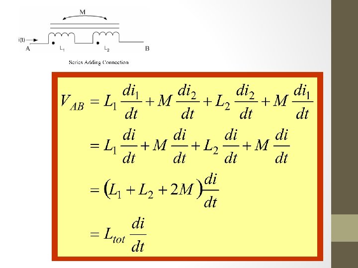
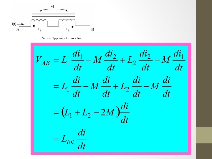
Dot convention for coils in series; the sign indicates the polarity of the mutual voltage; (a) series-aiding connection, (b) series-opposing connection. 17
Series Adding Connection (with two coils)
• Thus, for Series Adding Connection:
Series Opposing Connection (with two coils)
• Thus, for Series Opposing Connection:
EXAMPLE (Calculate the total inductance)
• For coil 1: • For coil 2: • For coil 3:
TIME DOMAIN ANALYSIS (Example 1) • Applying KVL • Coil 1 • Coil 2 26 Time-domain analysis of a circuit containing coupled coils
FREQ DOMAIN ANALYSIS (Example 2) • Applying KVL • Coil 1 • Coil 2 27 Frequency-domain analysis of a circuit containing coupled coils
Example 3 • Applying KVL for coil 1: 28
• Applying KVL for coil 2: 29
• Substituting I 2 in equation coil 1 30
CHAPTER OUTLINE • INTRODUCTION OF TRANSFORMER • MUTUAL INDUCTANCE • ENERGY IN A COUPLED CIRCUIT • LINEAR TRANSFORMERS • IDEAL TRANSFORMERS 31
ENERGY IN A COUPLED CIRCUIT • Energy stored in inductor is: Power in coil 1: Energy stored in coil 1: 32
• Maintain i 1=I 1 ; increase i 2 from zero to I 2. Power in coil 2: Energy stored in coil 2: 33
• Total energy stored in the coil when i 1 & i 2 reached constant value: • Since M 12 = M 21 = M • Coil current both entered the dotted terminals. 34
• If one current enters one dotted terminal while the other current leaves the other dotted terminal, the mutual voltage is negative. • Generally, energy stored in magnetically coupled circuit is: 35
• Energy stored in the circuit cannot be negative because the circuit is passive. • Coupling coefficient k is a measure of the magnetic coupling between two coils; 0 k 1 36
Example 4 Consider the circuit below. Determine the coupling coefficient. Calculate the energy stored in the coupled inductors at time t = 1 s if v=60 cos(4 t +30°) V. 37
• Coupling coefficient • Indicate that the inductors are tightly coupled. • Obtain the frequency-domain equivalent 38
• Mesh 1: • Mesh 2: 39
• Substituting I 2 in mesh 1 • In time-domain: 40
• Total energy stored: 41
LINEAR TRANSFORMER It is generally a four-terminal device comprising two or more magnetically coupled coils. • Primary coil is connected to voltage source. • Secondary coils is connected to the load. • R 1 and R 2 are included to calculate losses in coil. 42
• To obtain input impedance, Zin; KVL is applying in the two loop as below: • Substituting I 2 in I 1; the input impedance is: • where, 43
Equivalent circuit of Linear Transformer Can be divided into 2 equivalent; • T circuit • circuit. 44
Voltage-current relationship for primary and secondary coils Matrix equation: Matrix inversion: 45
Equivalent T circuit 46
• Mesh analysis is apply in T (or Y) network. • If T circuit and linear circuit are equivalent, then: 47
Equivalent circuit 48
• Nodal analysis is apply in (or ) network. • Equating terms in admittance matrices of above; obtain: 49
Example 5 In the circuit above, calculate the input impedance and current I 1. Take Z 1=60 -j 100Ω, Z 2=30+j 40Ω, and ZL=80+j 60Ω. 50
51
CHAPTER OUTLINE • INTRODUCTION OF TRANSFORMER • MUTUAL INDUCTANCE • ENERGY IN A COUPLED CIRCUIT • LINEAR TRANSFORMERS • IDEAL TRANSFORMERS 52
IDEAL TRANSFORMER • Is a unity-coupled (k=1), (k=1) lossless (R 1=R 2=0) transformer in which the primary and secondary coils have infinite selfinductances (L 1 &L 2 infinity) 53
• From Faraday’s law: • Voltage across primary winding is • Voltage across secondary winding is • Transformer ratio: 54
• Energy supplied to the primary must equal to energy absorbed by secondary since no losses in ideal transformer. • Primary and secondary currents are related to the turns ratio. Thus, 55
• Step-up transformer • If n 1, the voltage is increased from primary to secondary (V 2 V 1). • Step-down transformer • If n 1, the voltage decreased from primary to secondary (V 2 V 1). 56
Typical circuits in ideal transformer 57
• From the transformer turn ratio, the V 1, V 2, I 1 or I 2 can express as: • The complex power in primary winding for ideal is: 58
• Know that: • Since V 2/I 2 = ZL , thus: Also known as reflected impedance 59
Example 6 An ideal transformer is rated at 2400/120 V, 9. 6 k. VA, and has 50 turns on the secondary side. Calculate: (a) the turns ratio, (b) the number of turns on the primary side (c) the current ratings for the primary and secondary windings. 60
61