Elements of electrical engineering EEC 22215 Examination scheme
 • Examination scheme – 1. Theory(100 M) –")
 COURSE OUTCOME- Use principles of magnetic circuits")


 • The force which causes electrons to move is called as")


: Ø The current flowing in an electric")


 • Magnetic field strength (H) is defined as the")


: The ratio of the permeability of a given material or")


 oppose the flow Reluctance (S) is oppossition by")


 Self Induced EMF: Ø Self-induced e. m. f is the e. m. f")


– Inductance of the coil is defined as the property")
 Mutually Induced EMF: Ø The emf induced in a coil due to the")


- Slides: 66
Elements of electrical engineering (EEC- 22215) • Examination scheme – 1. Theory(100 M) – 1. End semester examination = 70 M (min- 28 M) 2. Progressive assessment = 30 M (10 M – Micro project, 20 M- Average of two class test ) 2. Practical(50 M) – Internal assessment = 25 M External assessment = 25 M Manual Submission = 25 M
1. Electric and Magnetic Circuits (08 M) COURSE OUTCOME- Use principles of magnetic circuits to solve engineering problems
Technical terms related to electric circuits 1. Current – Rate of flow of electrons is called as current. Denoted by I. Unit is Ampere (A) • Alternating current (AC): An AC is one which periodically passes through a definite cycle of changes in respect of magnitude as well as direction. • Direct current (DC): The DC is that current which flows continuously in one direction and has constant magnitude with respect to time.
A. C. and D. C. quantities
2. Potential difference • Potential difference is the work done in moving a unit of positive electric charge from one point to another. OR • The difference in electric potential between two points in an electric field; • The symbol for potential difference is V.
3. Electromotive force(EMF) • The force which causes electrons to move is called as electromotive force. • It is the electrical intensity or "pressure" developed by a source of electrical energy such as a battery or generator. • Voltage, also called electromotive force, is a quantitative expression of the potential difference in charge between two points in an electrical field.
4. Power - Electric power is the rate, per unit time, at which electrical energy is transferred by an electric circuit. The SI unit of power is the watt or one joule per second. Represented by the letter P. P = V*I …FOR DC circuits 5. Energy - E = P * t where t = time
Electric circuit concept
Electrical circuit An electric circuit is a path in which electrons from a electric energy source flow.
Every electric circuit has four basic parts: 1. Electrical Energy Source - a source of electrical energy, AC (alternating current, used in most homes) or DC (direct current) 2. Electrical conductors - electrical wires to carry electrical energy from its source to the point of use 3. Electrical Load - an electrical device that uses energy such as a light bulb, computer, or electric heater 4. Electrical Switches - controls to turn on or off electrical energy being supplied to an electrical load or device. In a home or other building electrical safety devices which protect the building from unsafe conditions such as a fire or electrical shock include circuit breakers or fuses which are really acting as an electrical "switch" to turn off electrical power should an unsafe condition occur.
Magnetic circuit
Magnetic circuit • A magnetic circuit is made up of one or more closed loop paths containing a magnetic flux. The flux is usually generated by permanent magnets or electromagnets and confined to the path by magnetic cores consisting of ferromagnetic materials like iron, although there may be air gaps or other materials in the path. • Magnetic circuits are employed to efficiently channel magnetic fields in many devices such as electric motors, generators, transformers, relays, lifting electromagnets, galvanometers, and magnetic recording heads.
Technical terms related to magnetic circuits 1. Magnetic Flux Ø The number of magnetic lines of forces set up in a magnetic circuit is called Magnetic Flux. It is analogous to electric current I in an electric circuit. Ø Its SI unit is Weber (Wb) and its CGS unit is Maxwell. Ø It is denoted by φ.
2. Flux Density: Ø Magnetic flux as flowing from the north pole of a magnet round to its south pole as shown by the arrows on the lines in the diagram. Looking at the diagram you should see that there is as much flux flowing ‘from the north pole’ as there is ‘flowing into the south pole’. Ø The amount of magnetic flux flowing through a given area will change from one point to another around the magnet. Ø In position B there a smaller number of magnetic field lines passing through the loop than there is when it is in position A. Ø Definition - The amount of flux passing through a unit area at right angles to the magnetic field lines is called as flux density (B).
Flux density = Flux / area through which flux passes B = Φ / A 2 Flux density is measured in Tesla (T) or Wb/m
3. Magnetomotive Force (M. M. F. ): Ø The current flowing in an electric circuit is due to the existence of electromotive force similarly magnetomotive force (MMF) is required to drive the magnetic flux in the magnetic circuit. Ø Definition - The magnetic pressure, which sets up the magnetic flux in a magnetic circuit is called Magnetomotive Force. MMF = N*I Where N= no of turns I = Current flowing in the coil The unit of MMF is Ampere-turn (AT).
ØThe strength of the MMF is equivalent to the product of the current around the turns and the number of turns of the coil. F = NI Where, N – numbers of turns of inductive coil I – current
5. Magnetic Force • The force exerted on one magnet by another one , either of attraction or repulsion is called the magnetic force. • According to Coulombs second low force between two magnetic pole is directly proportional to product of their pole strengths and inversely proportional to distance between them.
• Magnetic force is given by , F m 1*m 2 / d² Where , m 1 and m 2 = pole strength in wb d = distance between two magnetic poles in meter F = m 1 * m 2 / (4¶ µo µr d² ) F is in newtons
4. Magnetic Field Strength: ØThe force experienced by a unit north pole placed at any point in a magnetic field is known as magnetic field strength at that point. ØIt is represented by H ØIt units is newton per weber (N/Wb) or amperes per meter (A/m). H = B/ µ
4. Magnetic field strength (H) • Magnetic field strength (H) is defined as the m. m. f. per meter length of magnetic circuit i. e. , • Where, N = number of turns of a coil, • I = current (amperes), and • l = length of the magnetic circuit tm
Ex. 1. The following data relate to an electromagnet Total flux = 8 × 10 -4 Wb Cross sectional area of the core = 200 mm 2 Number of turns = 100 Magnitude of current = 2 A Length of the magnetic circuit = 400 mm Calculate the following: i. Flux density in the coil, ii. Magnetomotive force, and iii. Magnetic field strength.
Solution Total flux, ɸ = 8 × 10 -4 Wb Area of the coil, A = 200 mm 2 = 2 × 10 -4 m 2 Number of turns, N = 100 Current, I = 2 A Length of the magnetic circuit, l = 400 mm = 0. 4 m. i. Flux density in the coil, B : ii. Magnetomotive force, m. m. f. : m. m. f. = NI = 100 × 2 = 200 AT. (Ans. ) iii. Magnetic field strength, H: = 500 AT/M
5. Permeability • A property of magnetic material which indicates the ability of magnetic circuit to carry electromagnetic flux • It is the ratio of flux density to the magnetic field strength • In SI units, permeability is measured in henries per metre i. e. H·m− 1 • Permeability of free space or air or non magnetic material
6. Relative Permeability (μr): The ratio of the permeability of a given material or medium, to the permeability of free space. μr = μ/μ 0. where μ 0 = 4π × 10− 7
7. Reluctance: Ø Reluctance is the resistance to the flow of magnetic flux in a magnetic circuit. Ø It is denoted by S S = MMF / Flux S = F / φ S= N*I / φ • Where, l = the length of the conductor μo= permeability of vacuum. μr = relative permeability of the material. A = cross-section area of the conductor. Ø Its unit is AT / Wb
8. Permeance • The reciprocal of the magnetic reluctance is known as the magnetic permeance. It is given by the expression
9. Magnetic leakage factor- • Magnetic circuit :
9. Magnetic leakage factor • All the flux lines created by a current carrying coil may not be confined to the magnetic core associated with that coil. • The amount of flux which is perfectly confined in the magnetic core is known as useful flux. • The flux may be in very little amount which is not confined to the magnetic core is known as leakage flux. This flux is practically useless.
Magnetic leakage factor • Definition - The ratio of total flux created by a current carrying coil to the useful flux, confined in magnetic core is known as leakage factor.
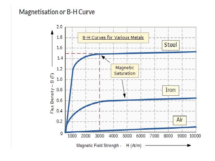
B-H Curve or Magnetizing curve • There is a relationship between magnetic flux density (B) and magnetising force (H). • The relationship is B = μ 0 μr H. – Where, μ 0 is the absolute permeability of air or free space and μr magnetic material. – The relation between magnetic induction density and magnetic force is partially linear since the relative permeability of a ferromagnetic material is not constant it changes with change in magnetic induction density or flux density. – The curve represents this relation between induction density (B) and magnetising force (H) is known as magnetising curve or B-H curve.
Magnetic Hysteresis • The phenomenon of flux density B lagging behind the magnetizing force H in a magnetic material is known as Magnetic Hysteresis. • when the magnetic material is magnetized first in one direction and then in the other direction, completing one cycle of magnetization, it is found that the flux density B lags behind the applied magnetization force H. • There are various types of magnetic materials such as paramagnetic, diamagnetic, ferromagnetic and antiferromagnetic materials. Ferromagnetic materials are mainly responsible for the generation of the hysteresis loop.
• When the magnetic field in not applied the ferromagnetic material behaves like a paramagnetic material. This means that at the initial stage the dipole of the ferromagnetic material is not aligned, they are randomly placed. As soon as the magnetic field is applied to the ferromagnetic material, its dipole moments align themselves in one particular direction as shown in the above figure, resulting in a much stronger magnetic field.
Experimental set up to draw the hysteresis loop
Hysteresis loop
• For understanding the phenomenon of the magnetic hysteresis, consider a ring of magnetic material wound uniformly with solenoid. The solenoid is connected to a DC source through a Double pole double throw (D. P. D. T) reversible switch as shown in the figure below. • Initially, the switch is in position 1. By decreasing the value of R the value of the current in the solenoid increases gradually resulting in a gradual increase in field intensity H, the flux density also increases till it reaches the saturation point a and the curve obtained is oa. Saturation occurs when on increasing the current the dipole moment or the molecules of the magnet material align itself in one direction. • Now by decreasing the current in the solenoid to zero the magnetizing force is gradually reduced to zero, but the value of flux density will not be zero as it still has the value ob when H=0, so the curve obtained is ab as shown in the figure below. This value ob of flux density is because of the residual magnetism.
• Now to demagnetize the magnetic ring, the position of the D. P. D. T reversible switch is changed to position 2 and thus, the direction of flow of the current in the solenoid is reversed resulting in reverse magnetizing force H. • When H is increased in reverse direction, the flux density starts decreasing and becomes zero (B=0) and the curve shown above follows the path bc. • The residual magnetism of the material is removed by applying the magnetizing force known as Coercive force in the opposite direction. • Now to complete the hysteresis loop the magnetizing force H is further increased in the reverse direction till it reaches the saturation point d but in the negative direction, the curve traces the path cd. • The value of H is reduced to zero H=0 and the curve obtains the path de, where oe is residual magnetism when the curve is in the negative direction.
• The position of the switch is changed to 1 again from the position 2 and the current in the solenoid is again increased as done in the magnetization process and due to this H is increased in the positive direction tracing the path as efa, and finally the hysteresis loop is complete. • In the curve again of is the magnetizing force, also known as the Coercive force required to remove the residual magnetism oe. • Here the total Coercive force required to wipe off the residual magnetism in one complete cycle is denoted by cf. • From the above discussion, it is clear that the flux density B always lags behind the magnetizing force H. Hence the loop ‘abcdefa’ is called the Magnetic Hysteresis loop or Hysteresis Curve.
• Residual Magnetism: The value of flux density when exciting current and therefore magnetic field strength is reduced to zero is called remanent or residual flux density. • Coercive Force: The value of the magnetizing force oc required to wipe out the residual magnetism ob is called Coercive force.
Analogy between electric and magnetic circuits Electric Circuit Path traced by the current is known as electric current. Magnetic Circuit Path traced by the magnetic flux is called as magnetic circuit. MMF is the driving force in the EMF is the driving force in the magnetic circuit. The unit is electric circuit. The unit is Volts. ampere turns. There is a current I in the electric circuit which is measured in amperes. There is flux φ in the magnetic circuit which is measured in the weber. The flow of electrons decides the current in conductor. The number of magnetic lines of force decides the flux.
Electric Circuit Magnetic Circuit Resistance (R) oppose the flow Reluctance (S) is oppossition by magnetic path to the flux. of the current. The Unit is ampere turn/weber. The unit is Ohm R = ρ. l/a. Directly proportional to l. Inversely proportional to a. Depends on nature of material. S = l/ (μ 0μra). Directly proportional to l. Inversely proportional to μ = μ 0μr. Inversely proportional to a The current I = EMF/ Resistance The Flux = MMF/ Reluctance The current density The flux density
Faraday's Law of Electromagnetic Induction • In 1831, Michael Faraday, an English physicist gave one of the most basic laws of electromagnetism called Faraday's law of electromagnetic induction. • This law explains the working principle of most of the electrical motors, generators, electrical transformers and inductors. • This law shows the relationship between electric circuit and magnetic field.
• Faraday performs an experiment with a magnet and a coil. During his experiment, he found how emf is induced in the coil when flux linked with it changes. • From this experiment, Faraday concluded that whenever there is relative motion between conductor and a magnetic field, the flux linkage with a coil changes and this change in flux induces a voltage across a coil.
• Faraday’s First Law: This law states that whenever the number of lines of force linking with a circuit changes, an emf is always induced in it; or whenever a conductor cuts or is cut by the magnetic flux, an emf is always generated in it. • Faraday’s Second Law: It states that the magnitude of the induced emf in any circuit is proportional to the rate of change of its flux linkages (flux x turns); or the magnitude of the generated emf in any conductor is proportional to the rate at which it cuts or is cut by the magnetic flux.
• Magnitude of the Induced EMF: Ø If the flux linking with a particular coil having N turns changes from φ1 to φ2 Webers in small time of ‘t’ seconds, then Rate of change of flux linkages = (Final flux linkage) – (Initial flux linkage) Time = Nφ2 – Nφ1 t Ø According to Faraday’s law of electromagnetic induction, the induced emf (e) is given by e ∝ Rate of change of flux linkages ∝ = Nφ2 – Nφ1 t e = N (φ2 – φ1) Volts t where K is the constant of proportionality. Expressing the above equation in differential form, we get e = N dφ dt
Direction of Induced EMF: • Direction of induced emf is given by following laws 1. Flemings right hand rule 2. Lenz’s law
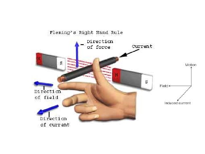
1. Fleming Right Hand Rule Ø If a conductor is forcefully brought under a magnetic field, there will be an induced current or EMF in that conductor. then direction of the induced current or EMF is given by Fleming’s Right Hand Rule. Ø Statement: Hold out the right hand with the first finger, second finger and thumb at right angle to each other. If first finger represents the direction of magnetic field (N to S), the thumb points in the direction of motion or applied force, then second finger points in the direction of the induced current.
2. Lenz’s Law • Lenz's law states that the direction of induced emf during the process of electromagnetic induction is always such that it will set up a current to oppose the basic cause responsible for inducing the emf. • The negative sign used in Faraday's law of electromagnetic induction, indicates that the induced emf and the change in magnetic flux have opposite signs.
Explanation of Lenz's Law CASE-I When a magnet is moving towards the coil. CASE-II When a magnet is moving away from the coil
Types of induced EMF • Nature of Induced EMF: Ø An Electromotive Force or EMF is said to be induced when the flux linking with a conductor or coil changes. Ø This change in flux can be obtained in two different ways; that is by statically or by dynamically induced emf.
Types of induced EMF
1. DYNAMICALLY INDUCED EMF: Ø In dynamically induced emf the magnetic field system is kept stationary, and the conductor is moving, or the magnetic field system is moving, and the conductor is stationary thus by following either of the two process the conductor cuts across the magnetic field and the emf is induced in the coil. Ø This phenomenon takes place in electric generators and back emf of motors and also in transformers.
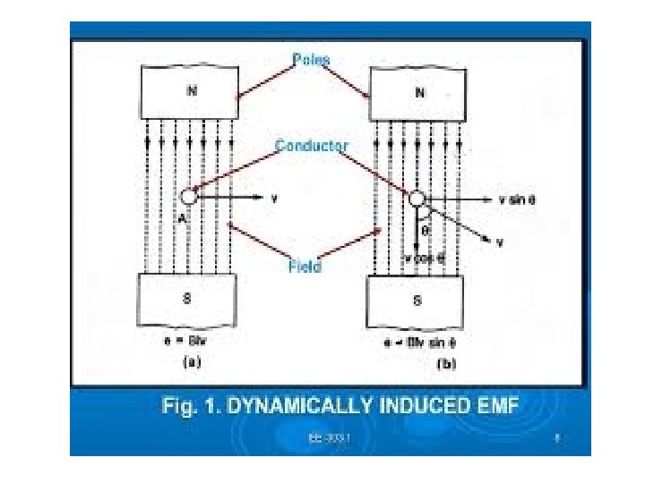
• Magnitude of Dynamically Induced EMF: Ø We can see from the figure that a conductor A is lied within a uniform magnetic field whose flux density is B Wb. Ø In this fig. the movement of the conductor is shown by arrow line. When the conductor A cuts across at right angles to the flux. Ø Let, ‘l’= Length of the conductor lying within the field. And it moves a distance dx in time dt, Ø So, the area swept by the conductor is =ldx. Hence, flux cut by the conductor = l. dx X B, Change in Flux = B. l. dx weber, Time= dt second
Ø According to Faraday’s laws. The e. m. f induced in the conductor. And this induced e. m. f is known as dynamically induced e. m. f. Ø If the conductor (A) moves at an angle θ with the direction of flux which is shown in (b).
2. STATICALLY INDUCED EMF: Ø This type of EMF is generated by keeping the coil and the magnetic field system, both of them stationary at the same time; that means the change in flux linking with the coil takes place without either moving the conductor (coil) or the field system. Ø This change of flux produced by the field system linking with the coil is obtained by changing the electric current in the field system. Ø It is further divided in two ways 1. Self-induced emf - emf which is induced in the coil due to the change of flux produced by it linking with its own turns. 2. Mutually induced emf - emf which is induced in the coil due to the change of flux produced by another coil, linking with it.
A) Self Induced EMF: Ø Self-induced e. m. f is the e. m. f which is produced in the coil due to the change of its own flux linked with it. If the current of the coil is changed, then the flux linked with its own turns will also change which will produce an e. m. f that is called selfinduced e. m. f. Ø Consider a coil having N number of turns as shown in the above figure. When the switch S is closed and current I flows through the coil, it produces flux (φ) linking with its own turns. If the current flowing through the coil is changed by changing the value of variable resistance (R), the flux linking with it, changes and hence emf is induced in the coil. This induced emf is called Self Induced emf. Ø The direction of this induced emf is such that it opposes its vary own cause which produces it, that means it opposes the change of current in the coil. This effect is because of the Lenz’s Law.
Self induced EMF
Magnitude of Self Induced EMF The magnitude of self induced emf is directly proportional to the rate of change of current in the coil. L is constant of proportionality and called as Self Inductance or the Coefficient of Self Inductance or Inductance of the coil.
SELF INDUCTANCE • Inductance (L)– Inductance of the coil is defined as the property of the coil due to which it opposes the change of current flowing through it. • where, N – number of turns in the coil Φ – magnetic flux I – current flowing through the coil The unit of inductance is Henry (H).
B) Mutually Induced EMF: Ø The emf induced in a coil due to the change of flux produced by another neighbouring coil linking to it, is called Mutually Induced emf. Ø Consider a coil A and B. Coil B is having N 2 number of turns and is placed near another coil A having N 1 number of turns as shown in the figure below. Ø When the switch (S) is closed in the circuit shown above current I 1 flows through the coil A, and it produces the fluxφ1. Most of the flux says φ2 links with the other coil B. Ø If the current flowing through the coil A is changed by changing the value of variable resistor R, it changes flux linking with the other coil B and hence emf is induced in the coil. This induced emf is called Mutually Induced emf.
Ø The direction of the induced emf is such that it opposes the cause which produces it, that means it opposes the change of current in the first coil. This effect of opposition caused by its own reason of production is called Lenz’s Law. Ø A galvanometer (G) is connected to the coil B for measuring the induced emf.
• Magnitude of mutually Induced EMF: Ø Let, N 1 = Number of turns of coil A N 2 = Number of turns of coil B I 1 = Current flowing through coil A Φ 1 = Flux producing due to current I 1 in webers. Φ 2 = Flux linking with coil B Ø According to Faraday’s law, the induced e. m. f in coil B is, E 2 = -N 2 (dΦ 2/dt) Ø Negative sign indicates that this e. m. f. will set up a current which will oppose the change of flux likning with it. Now Φ 2 = Φ 2/I 1 x I 1 Ø If permeability of the surrounds is assumed constant then Φ 2 ∝ I 1 and hence Φ 2/I 1 is constant. ∴ Rate of change of Φ 2 = (Φ 2/I 1) x Rate of change of current I 1 ∴ dΦ 2/dt = (Φ 2/I 1) x (d. I 1/dt) E 2 = -N 2 x ( Φ 2/I 1) x (d. I 1/dt) E 2 = - (N 2 Φ 2/I 1) (d. I 1/dt) Ø Here (N 2 Φ 2/I 1) is called coefficient of mutual inductance denoted by M. E 2 = -M(d. I 1/dt) Volts
Mutual Inductance • Mutual Inductance between the two coils is defined as the property of the coil due to which it opposes the change of current in the other coil.