CSC 600 Internetworking with TCPIP Unit 9 TCPIP
 Dr. Cheer-Sun")


 Analogous to virtual circuit in")

.")


 – Support for specific applications – AAL user")


 environment")


- Slides: 56
CSC 600 Internetworking with TCP/IP Unit 9: TCP/IP over ATM (ch. 18) Dr. Cheer-Sun Yang Spring 2001
Most of the slides were taken from William Stalling’s Book. William Stallings Data and Computer Communications Chapter 11 Asynchronous Transfer Mode and Frame Relay
Protocol Architecture • Similarities between ATM and packet switching – Transfer of data in discrete chunks – Multiple logical connections over single physical interface • In ATM flow on each logical connection is in fixed sized packets called cells • Minimal error and flow control – Reduced overhead • Data rates (physical layer) 25. 6 Mbps to 622. 08 Mbps
Protocol Architecture
Protocol Architecture
Reference Model Planes • User plane – Provides for user information transfer • Control plane – Call and connection control • Management plane – Plane management • whole system functions – Layer management • Resources and parameters in protocol entities
Control Plane • Between subscriber and network • Separate logical channel used – Similar to common channel signaling for circuit switching services • Data link layer – – – LAPD (Q. 921) Reliable data link control Error and flow control Between user (TE) and network (NT) Used for exchange of Q. 933 control signal messages
User Plane • End to end functionality • Transfer of info between ends • LAPF (Link Access Procedure for Frame Mode Bearer Services) Q. 922 – Frame delimiting, alignment and transparency – Frame mux and demux using addressing field – Ensure frame is integral number of octets (zero bit insertion/extraction) – Ensure frame is neither too long nor short – Detection of transmission errors – Congestion control functions
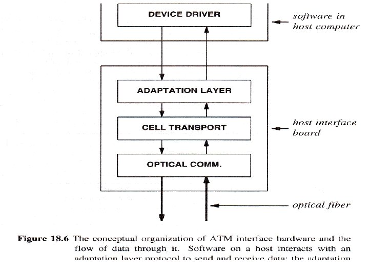
ATM Hardware
Large ATM Networks
The Logical View of an ATM Network
The Logical View of an ATM Network • The goal of ATM is an end-to-end communication system. • ATM hides the details of physical hardware. • ATM hardware provides attached computers with the appearance of a single, physical network.
ATM Logical Connections • • Virtual channel connections (VCC) Analogous to virtual circuit in X. 25 Basic unit of switching Between two end users Full duplex Fixed size cells Data, user-network exchange (control) and network-network exchange (network management and routing) • Virtual path connection (VPC) – Bundle of VCC with same end points
ATM Connections • ATM provides connection-oriented interface to attached hosts using two paradigms: – Permanent Virtual Circuits – Switched Virtual Circuits
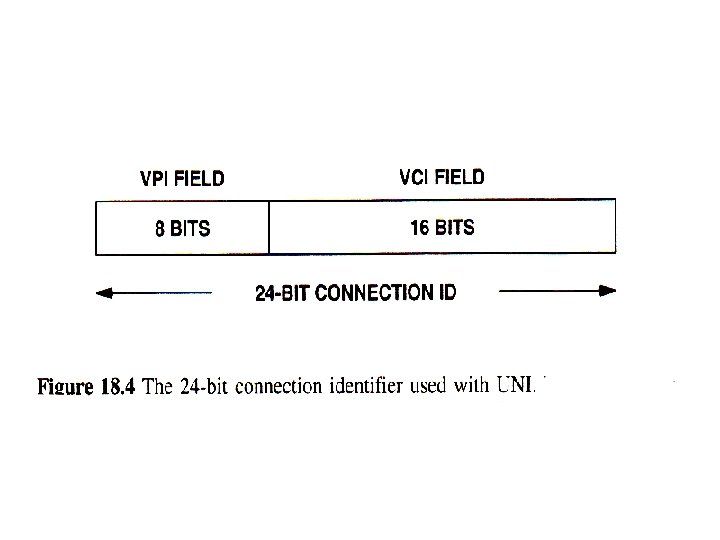
ATM Connections • ATM assigns each circuit a virtual circuit identifier (VCI).
ATM Connection Relationships
Advantages of Virtual Paths • Simplified network architecture • Increased network performance and reliability • Reduced processing • Short connection setup time • Enhanced network services
Call Establishment Using VPs
Virtual Channel Connection Uses • Between end users – End to end user data – Control signals – VPC provides overall capacity • VCC organization done by users • Between end user and network – Control signaling • Between network entities – Network traffic management – Routing
VP/VC Characteristics • Quality of service • Switched and semi-permanent channel connections • Call sequence integrity • Traffic parameter negotiation and usage monitoring • VPC only – Virtual channel identifier restriction within VPC
Control Signaling - VCC • Done on separate connection • Semi-permanent VCC • Meta-signaling channel – Used as permanent control signal channel • User to network signaling virtual channel – For control signaling – Used to set up VCCs to carry user data • User to user signaling virtual channel – Within pre-established VPC – Used by two end users without network intervention to establish and release user to user VCC
Control Signaling - VPC • Semi-permanent • Customer controlled • Network controlled
ATM Cells • • Fixed size 5 octet header 48 octet information field Small cells reduce queuing delay for high priority cells • Small cells can be switched more efficiently • Easier to implement switching of small cells in hardware
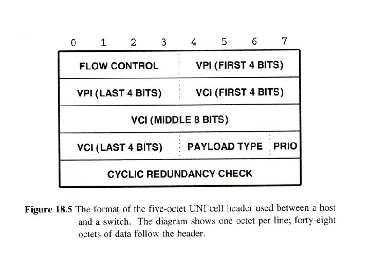
ATM Cell Format
Header Format • Generic flow control – Only at user to network interface – Controls flow only at this point • Virtual path identifier • Virtual channel identifier • Payload type – e. g. user info or network management • Cell loss priority • Header error control
Transmission of ATM Cells • • • 622. 08 Mbps 155. 52 Mbps 51. 84 Mbps 25. 6 Mbps Cell Based physical layer SDH based physical layer
Cell Based Physical Layer • No framing imposed • Continuous stream of 53 octet cells • Cell delineation based on header error control field
ATM Adaptation Layer • Support for information transfer protocol not based on ATM • PCM (voice) – Assemble bits into cells – Re-assemble into constant flow • IP – Map IP packets onto ATM cells – Fragment IP packets – Use LAPF over ATM to retain all IP infrastructure
Adaptation Layer Services • • Handle transmission errors Segmentation and re-assembly Handle lost and incorrectly inserted cells Flow control and timing
Supported Application types • • • Circuit emulation VBR voice and video General data service IP over ATM Multiprotocol encapsulation over ATM (MPOA) – IPX, Apple. Talk, DECNET) • LAN emulation
AAL Protocols • Convergence sublayer (CS) – Support for specific applications – AAL user attaches at SAP • Segmentation and re-assembly sublayer (SAR) – Packages and unpacks info received from CS into cells • Four types – – Type 1 Type 2 Type 3/4 Type 5
AAL Protocols
AAL Type 1 • CBR source • SAR packs and unpacks bits • Block accompanied by sequence number
AAL Type 2 • VBR • Analog applications
AAL Type 3/4 • Connectionless or connected • Message mode or stream mode
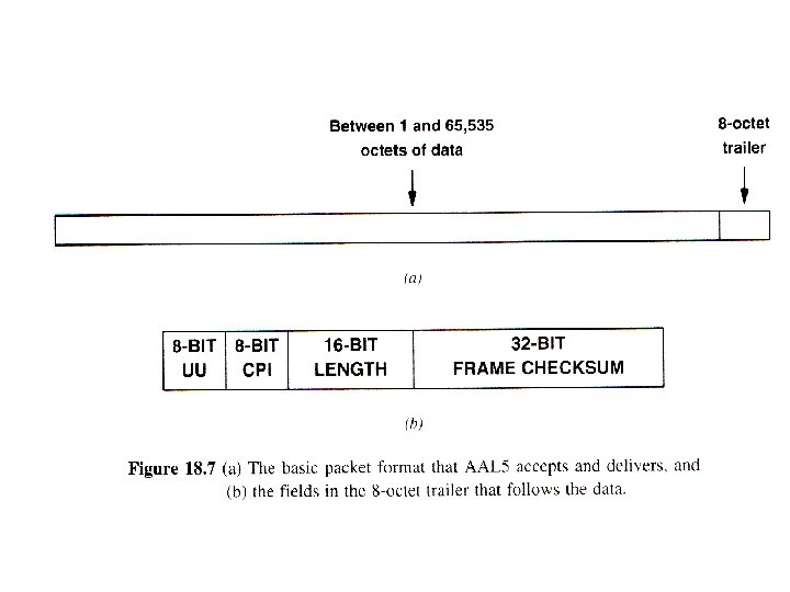
AAL Type 5 • Streamlined transport for connection oriented higher layer protocols
CPCS PDUs
Example AAL 5 Transmission
Segmentation and Reassembly PDU
Datagram Encapsulation and IP MTU Size • IP uses AAL 5 to transfer datagrams across an ATM network. • Before data can be sent, a virtual circuit (PVS or SVC) must be in place and both ends must agree to use AAL 5 on the circuit.
Datagram Encapsulation and IP MTU Size • To transfer a datagram, the sender passes it to AAL 5 along with the VPI/VCI identifying the circuit. • AAL 5 generates a trailer, divides the datagram into cells, and transfers the cells across the network. • At the receiving end, AAL 5 reassembles the cells, checks the CRC to verify that no bits were lost or corrupted, extracts the datagram, and passes it to IP.
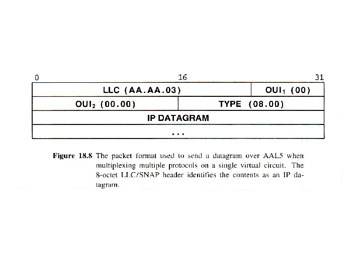
Datagram Encapsulation and IP MTU Size • When TCP/IP sends data across an ATM network, it transfers an entire datagram using ATM Adaptation Layer 5. Although AAL 5 can accept and transfer packets that contain up to 64 K octets, IP must fragment any datagram larger than 9180 octets before passing it to AAL 5 according to TCP/IP standard.
Packet Type and Multiplexing • The two computers at the end of a virtual circuit agree a priori that the circuit will be used for a specific protocol (e. g. , the circuit will only be used to send IP datagram). • The two computers at the ends of a VC agree a priori that some octets of the data area will be reserved for use as a type field.
IP Address Binding • IP address binding in a non-broadcast multiple access (NBMA) environment can be difficult.
Difficulties RE IP Address Binding – ATM physical address is larger than an IP address – ATM hardware does not support broadcast; ARP cannot be used to resolve address mapping.
Difficulties RE IP Address Binding – An ATM network manager manually configures each PVC, a host only knows the circuit’s VPI/VCI pair. Software on this host may not know the IP address of the remote host. – Switched connection-oriented technologies further complicate address binding because they require two levels of binding. First, when creating a virtual circuit, the dest. IP address must be mapped to an ATM endpoint address. Second, when sending a datagram, the dest IP address must be mapped to the VPI/VCI pair for the circuit.
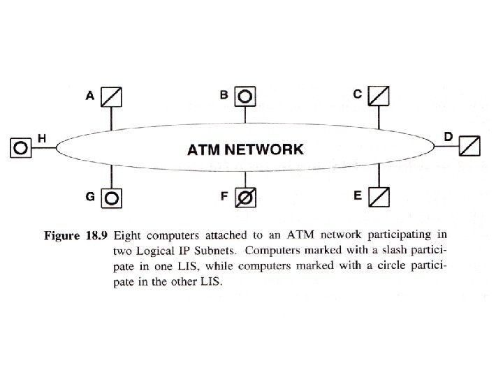
Logical IP Subnet Concept • Although no protocol has been proposed to solve the general case of address binding, a protocol has been devised for a restricted form. • The case aries when a group of computers uses an ATM network in place of a LAN. The group formss a Logical IP Subnet (LIS). • Multiple LISs can be defines among a set of computers that all attached to the same ATM hardware network.
Logical IP Subnet Concept • ATM allows a subset of computers attached to an ATM network to operate like an independent LAN. • Computers in the same LIS share a single IP network prefix. • A computer must use a router to communicate with a computer in another LIS.
Unanswered Questions • How can switching hardware be exploited to forward IP traffic at higher speeds? • How does Label Switching work? • How can IP forwarding be optimized?
Suggested Reading • • Stallings Chapter 11 ATM Forum Web site Newman et. al. [April 1998]: IP Switching Laubach and Helpern [RFC 2225]: logical IP subnet, ATMARP, default MTU