Chapter 4 1 HYDRAULICS Fluid Dynamics FLUID DYNAMICS

 which are acting on an object for a")

 Pressure force (Fp) Viscous force (Fv) Surface")


 Pitot Tube Dynamic pressure = Converting this to head")


 VENTURI METER")


 ORIFICE AND MOUTH PIECES SMALL ORIFICE")


 Time required to empty a tank of uniform")


 Flow from one tank to another through an")
 Flow from one tank to another through an")
 Flow from one tank to another through an")

 Notches and Weirs : hydraulic structures for measuring discharge.")


- Slides: 60
Chapter 4 -1 HYDRAULICS Fluid Dynamics
FLUID DYNAMICS Hydrostatics forces (pressure forces) which are acting on an object for a liquid at rest Hydro kinematics fluid flow phenomena related with space time variation (velocity and acceleration) without considering the effect of force But in dealing with dynamics of fluid flow, all forces that affect the phenomenon, the resulting acceleration and energy changes are considered.
EQUATIONS OF MOTION Just as in mechanics of solids, the mechanics of fluids is also governed by Newton's Second Law of motion. i. e. Force = Mass x acceleration Thus, in the x-direction, for example, Newton's Equation of motion will be: Since liquids do not possess rigidity, their mass center changes unlike that of solids. Therefore, for fluids mass per unit volume is more important than the total mass.
FORCES INFLUENCING FLUID MOTION Gravity force (Fg) Pressure force (Fp) Viscous force (Fv) Surface tension (Fs) Force due to compressibility (Fe) Force due to turbulence (Ft) For example, in x-direction, the summation of the forces,
FORCES INFLUENCING FLUID MOTION In most of the problems of the fluids in motion the surface tension forces and the compressibility forces are not significant Reynold’s equations of motion For laminar or viscous flows the turbulent forces also become less significant and hence these may be neglected. Navier - Stokes’ equations of motion If the viscous forces are also of little significance in the problems of fluid flows, then these forces may also be neglected. Euler’s equations of motion
FORCES INFLUENCING FLUID MOTION Gravity force: The gravity force per unit volume is expressed as: Fg = g Pressure force: To determine the magnitude of the pressure force per unit volume,
EULER’S EQUATION OF MOTION A simplifying approach to a fluid problem is usually made by assuming the fluid to be ideal or perfect. i. e. Euler’s Equation is mostly used. Thus, introducing to replace Fp, we will have: Euler’s Equation for one dimensional flow Thus, the general three dimensional form of Euler‘s Equation: X, Y, and Z = unit weight per unit mass in the respective directions.
BERNOULLI’S EQUATION The integration of Euler's Equation along a streamline results in an important equation in fluid mechanics known as Bernoulli's Equation. Consider the forces acting on a fluid element of cross-sectional area d. A and length ds along a stream line
BERNOULLI’S EQUATION Thus: Gravity force in the direction of motion = Pressure force in the direction of motion = If v = velocity in the direction of motion, then Euler's equation: Dividing by d. A. ds , one gets: But,
BERNOULLI’S EQUATION Considering for steady flow, and substituting Integrating along a stream line: Thus, Bernoulli’s Equation for compressible and incompressible flow
BERNOULLI’S EQUATION For incompressible fluid, = constant, Energy per unit mass It can also be written as: Energy per unit weight Or Energy per unit volume ---- Velocity head or kinetic energy per unit weight ---- pressure head or pressure energy per unit weight --- elevation or potential head
BERNOULLI’S EQUATION Bernoulli's Equation states that in a steady flow of an ideal fluid, the sum of velocity head, pressure head and potential head along a stream line is constant. Or Bernoulli's Equation can also be stated as: The total energy per unit weight for a steady flow of an ideal fluid remains constant along a stream line. Applying it between two sections, H= constant = H = the total head or total Energy head
REMEMBER - ENERGY AND HEAD Potential energy /elevation /positional energy/ = Potential energy per unit weight = Z (meters) = Potential head Pressure energy: Force due to pressure P on stream of fluid with cross- section area A is PA. If a weight W of liquid passes through the cross section, Volume passing in cross section = Distance moved by liquid = Work done = F* S = Pressure energy per unit weight = = = pressure head Kinetic energy If a mass of fluid (m) moves at some velocity (v), Kinetic energy = ½ m. V 2 = ½ W/g v 2 = Kinetic energy per unit weight = Total head = potential head + pressure head + velocity head = = kinetic
PRESSURE HEAD, VELOCITY HEAD, POTENTIAL HEAD AND TOTAL HEAD When the pipe is closed
PRESSURE HEAD, VELOCITY HEAD, POTENTIAL HEAD AND TOTAL HEAD When the pipe is opened
PRESSURE HEAD, VELOCITY HEAD, POTENTIAL HEAD AND TOTAL HEAD When the pipe does not have constant diameter
EXCHANGE BETWEEN PRESSURE HEAD AND VELOCITY HEAD
EXCHANGE BETWEEN PRESSURE HEAD AND VELOCITY HEAD
THE ENERGY EQUATION For real fluids, some energy is converted into heat due to viscous shear and consequently there is a certain amount of energy loss. In other words, H decreases due to friction losses hf and other losses caused by sudden changes in section or alignment. Thus, for real fluids, Bernoulli's equation becomes: Where, subscripts (1) and (2) = the two sections under consideration h. L 1 -2 = the energy loss per unit weight of fluid between the two sections.
THE ENERGY EQUATION
HYDRAULIC GRADE LINE AND ENERGY LINE Pipe discharging water from a reservoir freely to the atmosphere Reservoirs connected by varying diameter pipes
HYDRAULIC GRADE LINE AND ENERGY LINE
HYDRAULIC GRADE LINE AND ENERGY LINE HGL and EGL in open channel flow Note: The free surface is the hydraulic grade line
THE ENERGY EQUATION Example 1: A closed tank of a fire engine is partly filled with water, the air space above the water being under pressure. A 5 cm diameter hose connected to the tank discharges on the roof of a building 4. 0 m above the level of water in the tank. The frictional head loss in the hose is equivalent to 40 cm head of water. What air pressure must be maintained in the air in the tank to deliver 12 t/s on the roof?
THE ENERGY EQUATION
THE ENERGY EQUATION
THE ENERGY EQUATION Example 2: A pipeline carrying a discharge of 0. 12 m 3/s changes from 150 mm diameter to 300 mm diameter and rises through 7 m. Calculate the pressure in the 300 mm pipe when the pressure in the 150 mm pipe is 350 k. N/m 2.
APPLICATIONS OF BERNOULLI’S EQUATION A) Pitot Tube Dynamic pressure = Converting this to head Dynamic head = The total pressure is known as the stagnation pressure. Stagnation pressure = Stagnation head =
PITOT TUBE
PITOT TUBE If h 2 -h 1 =h, The real velocity is Where, C = pitot tube coefficient, usually 0. 95 -1. 00
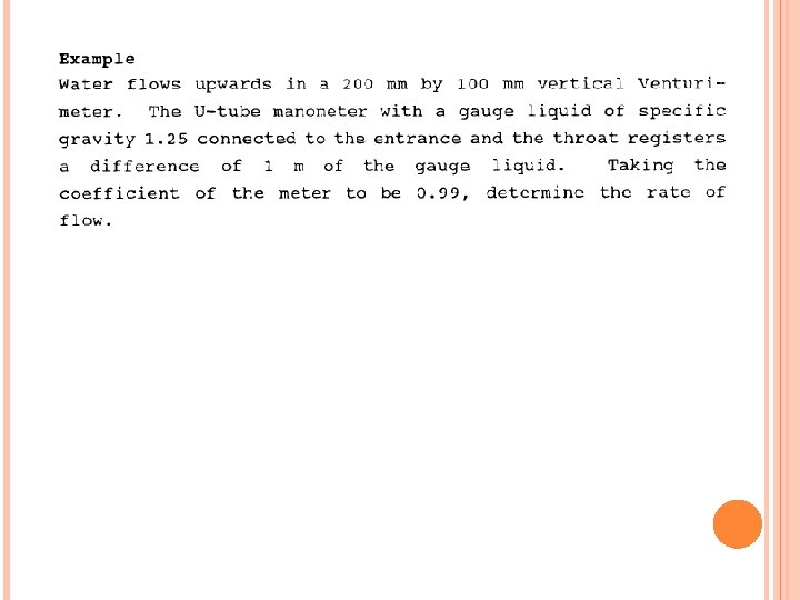
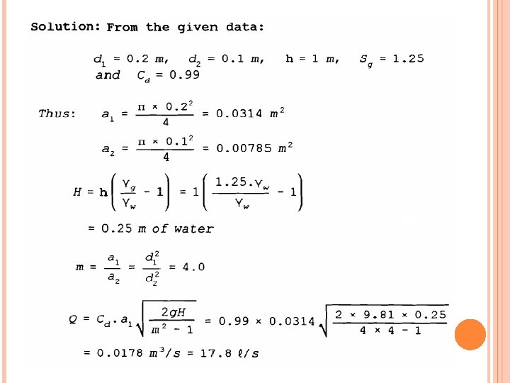
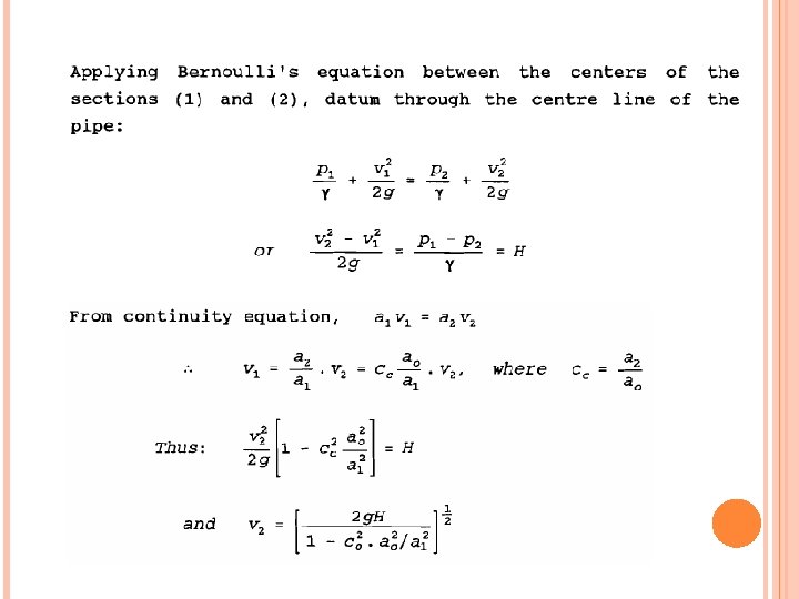
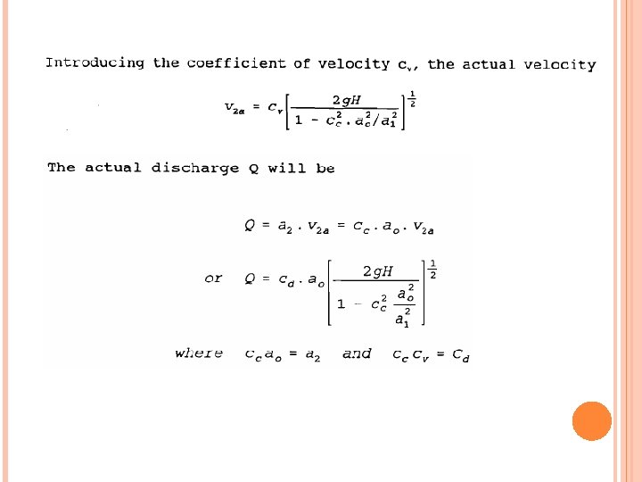
B) VENTURI METER
VENTURI METER Note: For horizontal venturi, z 1=z 2
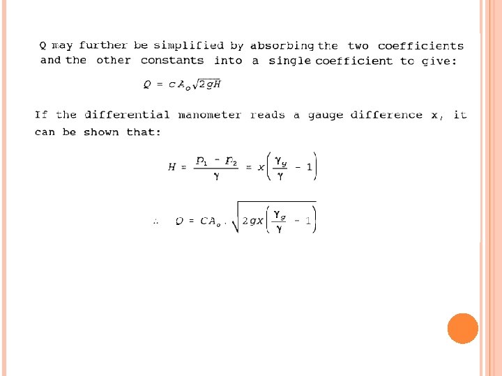
VENTURI METER
C) ORIFICE AND MOUTH PIECES SMALL ORIFICE
Neglecting air resistance and horizontal velocity, v assumed constant, the distance the fluid traveled in time t is: The vertical distance y, From the two,
SMALL ORIFICE
SMALL ORIFICE Hydraulic coefficients for typical orifices and mouthpieces
ORIFICE METER
Large Orifice: when the vertical height of the orifice is large so that the head producing the flow is substantially less at the top of the opening than at the bottom. The discharge calculated using the formula of small orifice, where the head H is measured to the centre of the orifice, will not be the true value since the velocity will vary substantially from top to bottom of the opening. In this case theoretical discharge is calculated by integrating from top to bottom the flow. Consider a large rectangular orifice of width B and depth D
As shown in the figure, the top and bottom of the orifice opening are at depth H 1 and H 2 respectively below the free surf ace. Consider a horizontal strip across the opening of height dh at a depth h below the free surface. Area of the strip = Bdh Velocity of flow through the strip = Discharge through the strip, To obtain the discharge through the whole opening, integrate d. Q from h = H 1 to h = H 2 Threfore, discharge The actual discharge
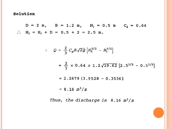
Example 1. Water flows from a reservoir through a rectangular opening 2 m high and 1. 2 m wide in the vertical face of a dam. Calculate the discharge in m 3/s when the free surface in the reservoir is 0. 5 m above the top of the opening assuming coefficient of discharge of 0. 64.
UNSTEADY FLOW THROUGH SMALL ORIFICE Problem of discharge through an orifice under varying head strictly fall under unsteady flow. But if the rate of fall of the head is very small compared to the velocity of efflux, Bernoulli's equation may be conveniently applied without appreciable error. Two practical cases of unsteady flow through small orifice are: i) Time required for a desired fall of liquid level in a tank due to efflux from an orifice. ii) Flow from one tank to another.
UNSTEADY FLOW THROUGH SMALL ORIFICE 1) Time required to empty a tank of uniform cross-section: Consider a tank of uniform cross-sectional area A discharging liquid through an orifice of cross-sectional area a installed at its bottom.
UNSTEADY FLOW THROUGH SMALL ORIFICE Time required to empty a tank of uniform cross-section: Let the height of the liquid be at h above the vena contracta at some instant. The theoretical outflow velocity at that instant will be: Let the liquid level fall by an amount dh during a time interval dt. The volume of liquid that has flown out in time dt will be: Volume of liquid that has passed through the orifice in the same time interval dt will be: Thus:
UNSTEADY FLOW THROUGH SMALL ORIFICE Time required to empty a tank of uniform cross-section: The time T required for the liquid level to drop from H 1 to H 2 may be found by integrating the above equation between the limits H 1 and H 2. Since H 1 > H 2 , the term in brackets is negative, thus T will be positive. Taking the minus sign out of the bracket: Note: The tank will be fully emptied when H 2 = 0.
UNSTEADY FLOW THROUGH SMALL ORIFICE 2) Flow from one tank to another through an orifice: Consider two adjacent tanks of uniform cross-sectional area A 1 and A 2 connected by an orifice of cross-sectional area a. Let, H 1 = initial difference between the liquid levels in the two tanks H 2 = final difference in level between the liquid levels in the two tanks
UNSTEADY FLOW THROUGH SMALL ORIFICE 2) Flow from one tank to another through an orifice: At any instant, let the difference in levels be H. The theoretical velocity of the liquid through the orifice at this instant is: After a small time interval dt, let the fall in head in tank A 1 be dh. The volume that has gone out of tank A 1 will be dh A 1. If y is the change in level of tank A 2, then the volume entering tank A 2 in time dt will be y. A 2. From continuity,
UNSTEADY FLOW THROUGH SMALL ORIFICE 2) Flow from one tank to another through an orifice: Then the total change in head difference between A 1 and A 2 will be: Equating the flow through the orifice for the time dt to the volume of displacement: Integrating the above between H 1 and H 2, the time T required for the level difference in the two tanks to drop from H 1 to H 2 is: Note: The time required for the level between the two tanks to equalize is obtained when H 2 = 0.
UNSTEADY FLOW THROUGH SMALL ORIFICE Example. A rectangular tank 10 m x 6 m has an orifice with 10 cm diameter fitted at its bottom. It water stands initially at a height of 5 m above the orifice, what time is required for the level to drop to 1 m above the orifice. Take the orifice coefficient to be 0. 64. Solution:
APPLICATION OF BERNOULLI’S EQUATION d) Notches and Weirs : hydraulic structures for measuring discharge.
Rectangular Weir Trapezoidal Weir Triangular Weir
APPLICATION OF BERNOULLI’S EQUATION Example 1. Determine the discharge over a sharp-crested rectangular weir with 8 m crest length and a head of 2. 4 m. The width of the approach channel is 10 m. Take Cd= 0. 622.
UNSTEADY FLOW THROUGH SMALL ORIFICE Example 2. A 90 o V-notch has a discharge coefficient of 0. 60. Calculate the discharge when the observed head is 0. 65 m.
THANK YOU