3 5 Destressing Criteria for destressing method of





- Slides: 40
3. 5 De-stressing: Criteria for destressing, method of destressing without tensor/ with Rail tensors. Periods- 6
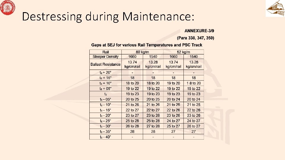
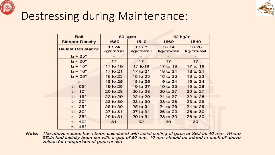
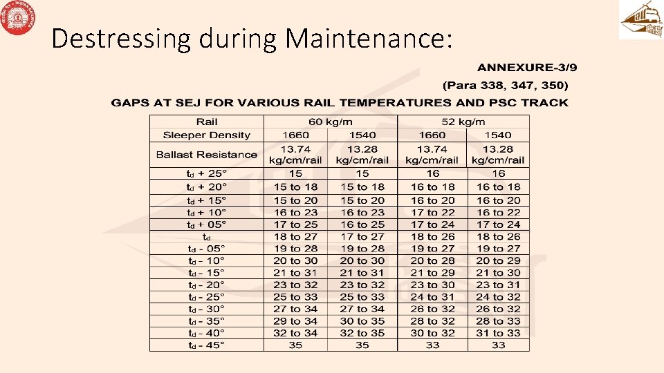
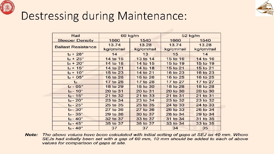
Destressing during Maintenance: • (1) Abnormal behaviour of LWR/CWR can be inferred by observing one or more of the following: (a) When the gap observed at SEJ • (i) Differs beyond limits specified in Annexure - 3/9. • (ii) Exceeds the maximum designed gap of SEJ • (iii) When tip of tongue rail/corner of Stock Rail crosses the reference line (b) In case of excessive creep of more than 20 mm in the central portion of LWR is noticed.
Destressing during Maintenance:
Destressing during Maintenance:
Destressing during Maintenance:
Destressing during Maintenance:
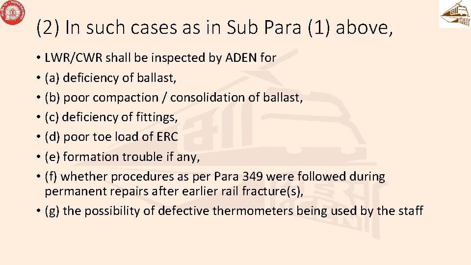
(2) In such cases as in Sub Para (1) above, • LWR/CWR shall be inspected by ADEN for • (a) deficiency of ballast, • (b) poor compaction / consolidation of ballast, • (c) deficiency of fittings, • (d) poor toe load of ERC • (e) formation trouble if any, • (f) whether procedures as per Para 349 were followed during permanent repairs after earlier rail fracture(s), • (g) the possibility of defective thermometers being used by the staff
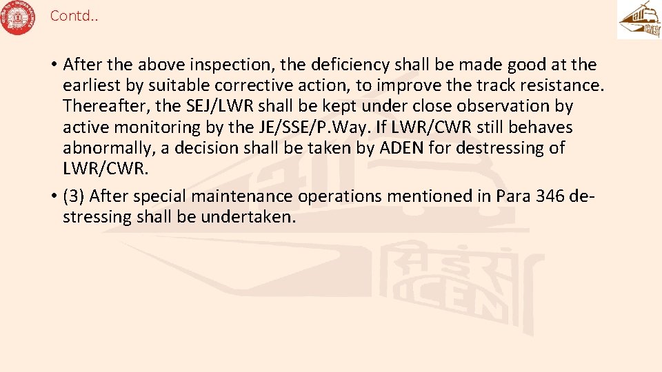
Contd. . • After the above inspection, the deficiency shall be made good at the earliest by suitable corrective action, to improve the track resistance. Thereafter, the SEJ/LWR shall be kept under close observation by active monitoring by the JE/SSE/P. Way. If LWR/CWR still behaves abnormally, a decision shall be taken by ADEN for destressing of LWR/CWR. • (3) After special maintenance operations mentioned in Para 346 destressing shall be undertaken.
Contd. . • (4) After restoration of track following an unusual occurrence mentioned in Para 348 of IRPWM, destressing shall be undertaken. • (5) If number of locations where repairs by way of replacement of rail / weld have been done, exceed three per km, de-stressing of affected portion of LWR / CWR shall be done
De-stressing operation of LWR • The work of de-stressing shall be done during a traffic block under the personal supervision of JE/SSE/P. Way. • De-stressing shall be done when rail temperature falls between the range provided for td. If required temperature cannot be obtained in field, de-stressing can be done at a little lower temperature than the targeted stress-free temperature to with the use of rail tensors.
De-stressing without Rail Tensors • In case rail temperature at the time of de-stressing is within the range specified for td, detailed procedure as given below may be adopted. • (1) The LWR, if longer than manageable lengths that cannot be destressed at a time, then, the LWR shall be de-stressed in parts by tackling manageable lengths depending on the availability of Block, labour etc. • (2) Remove impediments to free movement of rail such as rail anchors, guard rails, check rails etc.
De-stressing without Rail Tensors • (3) A traffic block of adequate duration should be arranged at such a time that the rail temperature will be within the temperature range specified for td during the fastening down operations of fittings. • (4) Before the traffic block is actually taken, a speed restriction of 30 km/h should be imposed and fastenings on alternate sleepers loosened. • (5) When the traffic block is taken, a closure rail near the SEJ shall be cut and removed, the SEJs adjusted as per Para 338(1) (b) and fastened.
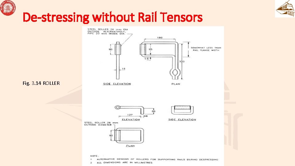
De-stressing without Rail Tensors • (6) The remaining fastenings on both running rails shall be loosened/removed starting from the ends near the SEJs and proceeding towards the centre of LWR. The rail shall be lifted and placed on rollers Fig. 3. 14 at every 15 th sleeper to permit the rails to move freely. While de-stressing on curved track, provision of side rollers as per Para 341(6) (a) & (b) may be adopted. The rails shall be struck horizontally with wooden mallets to assist in their longitudinal movement.
De-stressing without Rail Tensors Fig. 3. 14 ROLLER
De-stressing without Rail Tensors • (7) The rollers shall then be removed, the rails lowered to correct alignment and fastenings tightened, starting from the middle of LWR and proceeding towards both ends simultaneously. The tightening of fastenings shall be completed within the temperature range for td. The actual range of temperature during the period of tightening shall be recorded by JE/SSE/P. Way along with the time and date.
De-stressing without Rail Tensors • (8) Simultaneously with the tightening of fastening, arrangements for insertion of cut rails, 4 metre or longer, between the SEJ and LWR shall be started. The four gaps shall be measured individually and the rails of required length cut by saw keeping required gaps for AT welding. The cut rails shall then be placed in position, fastened to the sleepers and welded at each end. Fastenings for 20 m on each end of the LWR shall be removed before welding.
De-stressing with Rail Tensors • For de-stressing of LWR with the use of rail tensor, the following procedure shall be adopted: • (1) The LWR, if longer than manageable lengths that can be destressed at a time, then, the LWR shall be de-stressed in parts by tackling manageable lengths depending on the availability of Block, labour and the capacity of the tensor available etc. • (2) Remove impediments to free movement of rail such as rail anchors, guard rails, check rails etc.
De-stressing with Rail Tensors • (3) During the traffic block, create a gap of 1 m at location ‘B’ i. e. centre of the first segment of the LWR (Fig. 3. 22). • (4) Mark the anchor length A 1 A 2 and C 1 C 2 each equal to la at either end of the length A 2 C 2 to be de-stressed (Fig. 3. 22 (a)).
De-stressing with Rail Tensors • Note: The anchor length ‘la’ should be determined on the basis of the lowest value of tp at which the de-stressing is likely to be carried out. Anchor length shall be increased suitably based on the condition of the fastenings, rubber pads, liners or ballast.
De-stressing with Rail Tensors (5) Erect marker pillars W 0 W 1 etc. , on each of the length A 2 B and C 2 B. Transfer the marks W 0 onto the rail foot (Fig: 3. 22 (a)). Note: The distances W 0 W 1, W 1 W 2 etc. shall be marked at about 100 m intervals, the distance from the previous pillars and the last pillar WB may be less than 100 metre.
De-stressing with Rail Tensors (6) when t. P is less than the desired to (Fig. 3. 22 (b)), de-stressing operation shall be carried out for the lengths A 2 B and C 2 B as described below: - (Back to Para 340(6)) (a) Unfasten and mount on rollers the portion from A 2 C 2. Note: Side rollers on the inside of curve shall also be used while undertaking destressing on curved track these should be spaced at every nth sleeper, Where, n = Radius of curve (R) x No. of sleepers per rail length 50 x (to-tp) (b) Outside supports shall be used in addition at the rate of one for every three inside supports.
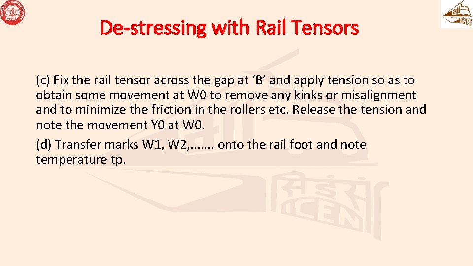
De-stressing with Rail Tensors (c) Fix the rail tensor across the gap at ‘B’ and apply tension so as to obtain some movement at W 0 to remove any kinks or misalignment and to minimize the friction in the rollers etc. Release the tension and note the movement Y 0 at W 0. (d) Transfer marks W 1, W 2, . . . . onto the rail foot and note temperature tp.
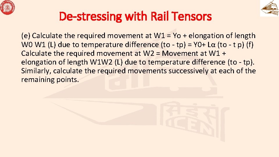
De-stressing with Rail Tensors (e) Calculate the required movement at W 1 = Yo + elongation of length W 0 W 1 (L) due to temperature difference (to - tp) = Y 0+ Lα (to - t p) (f) Calculate the required movement at W 2 = Movement at W 1 + elongation of length W 1 W 2 (L) due to temperature difference (to - tp). Similarly, calculate the required movements successively at each of the remaining points.
De-stressing with Rail Tensors (g) Mark the above calculated extensions with respect to the transferred marks referred at (d) above on the rail foot on the side away from the tensor. (h) Apply the tension by means of rail tensor till the mark of required extension comes opposite to the mark on the marker pillar W 1. Fasten down the segment W 0 W 1 (i) Then check at W 2, bring the mark of required extension at this location opposite to the mark on the marker pillar W 2, by adjusting the tensor either by reducing or increasing tension and fasten down the segment W 1 W 2. Similarly, check the remaining marks, adjust the tension as required and fasten down each segment before proceeding to the next segment.
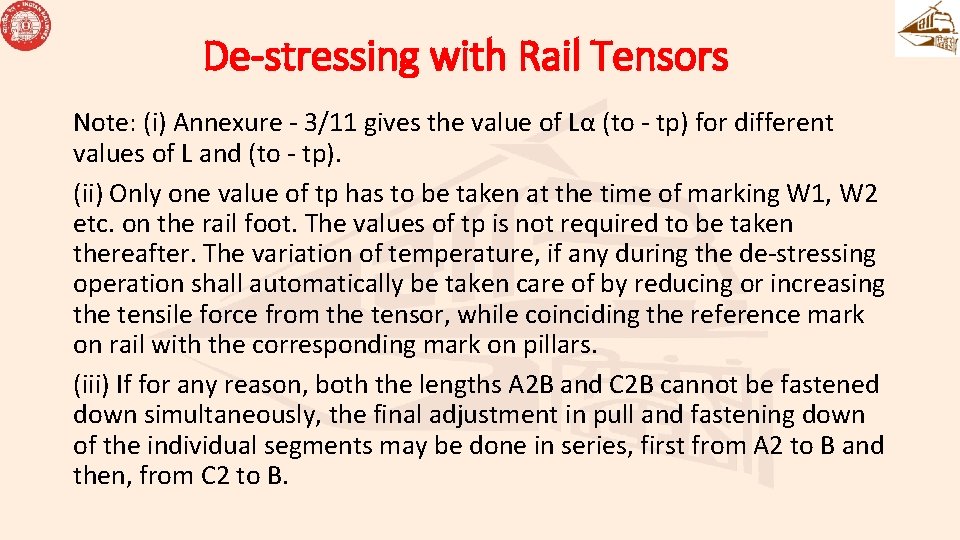
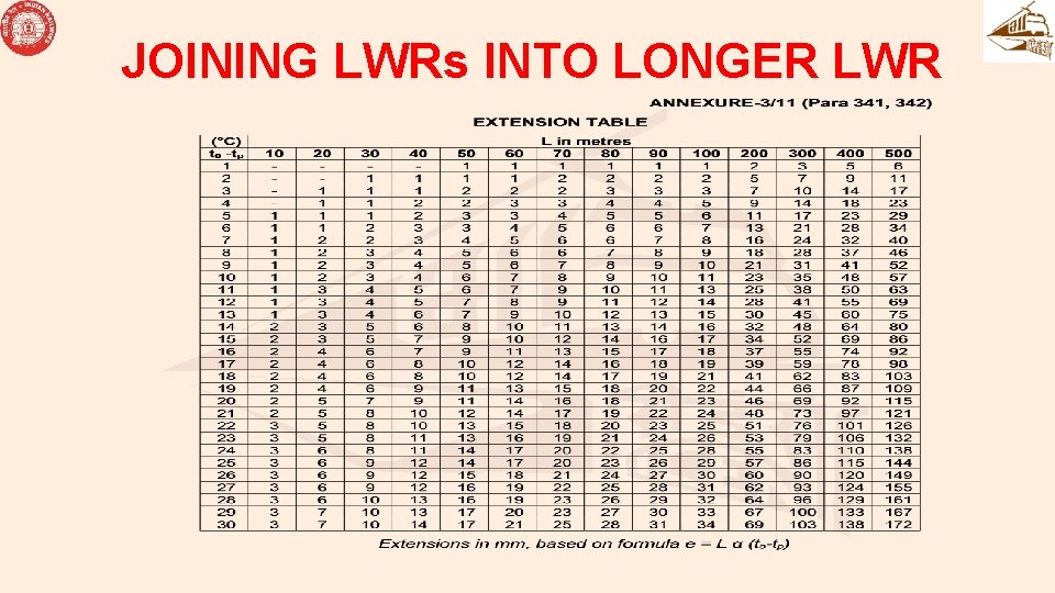
De-stressing with Rail Tensors Note: (i) Annexure - 3/11 gives the value of Lα (to - tp) for different values of L and (to - tp). (ii) Only one value of tp has to be taken at the time of marking W 1, W 2 etc. on the rail foot. The values of tp is not required to be taken thereafter. The variation of temperature, if any during the de-stressing operation shall automatically be taken care of by reducing or increasing the tensile force from the tensor, while coinciding the reference mark on rail with the corresponding mark on pillars. (iii) If for any reason, both the lengths A 2 B and C 2 B cannot be fastened down simultaneously, the final adjustment in pull and fastening down of the individual segments may be done in series, first from A 2 to B and then, from C 2 to B.
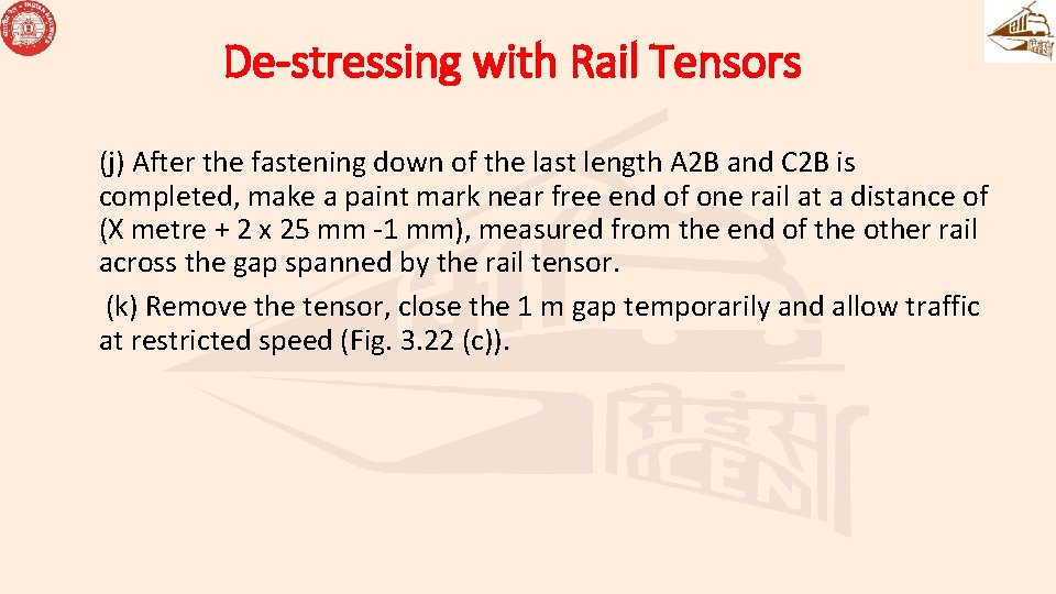
De-stressing with Rail Tensors (j) After the fastening down of the last length A 2 B and C 2 B is completed, make a paint mark near free end of one rail at a distance of (X metre + 2 x 25 mm -1 mm), measured from the end of the other rail across the gap spanned by the rail tensor. (k) Remove the tensor, close the 1 m gap temporarily and allow traffic at restricted speed (Fig. 3. 22 (c)).
De-stressing with Rail Tensors (7) During traffic block, cut the rail at the paint mark, insert a rail closure of length exactly equal to X metre and weld one end thereof (Fig. 3. 22 (d)). If the gap at the other end is also 25 mm, it can be welded in the same block. Otherwise, fasten with special fishplates and clamps and allow traffic at restricted speed. In the latter case, during a subsequent block, when tp is not greater than to, release rail fastenings on either side to the required extent of about 50 to 75 m and pull the rails with rail tensor to get the desired gap of 25 mm (Fig. 3. 22 (e)); refasten the rail and weld the joint. Release the tensor after a lapse of a minimum of 30 minutes after pouring of the weld metal
De-stressing with Rail Tensors Note: - (i) X=4 metre or longer (ii) In case gap at the time of the second weld as above is less than the desired welding gap, additional cutting of rail shall NOT be done to create correct gap for welding. In such cases, the welding should be done below td and the requisite gap for welding shall be created by using rail tensor and equalization of forces as described below shall be done. (8) During a traffic block, when tp is less than td, equalize the forces in the rail by releasing the fastenings over a length of minimum 125 m on either side of location ‘B’ and tapping with wooden mallets etc. (Fig. 3. 22 (f)).
De-stressing with Rail Tensors
De-stressing with Rail Tensors (9) The above procedure should be repeated for the remaining segments, if the entire LWR is to be de-stressed. (10) During another traffic block, when tp is within the range of temperature specified for td, destress the end 125 metre from SEJ. Thereafter, weld the closure rail next to SEJ duly ensuring setting of the gaps at SEJ as per Para 338.
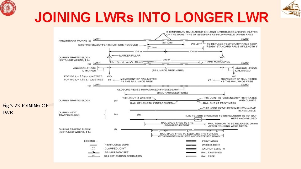
JOINING LWRs INTO LONGER LWR Joining of LWRs: Detailed procedure for joining of LWRs is as given below (Fig. 3. 23 (a) to (f)): (1) During traffic block, replace the existing SEJs between the LWRs with ordinary rails, of which there should be two temporary rails about 4 metre or longer for each of left and right sides. Leaving the temporary rails fish-plated, weld the other rails and traffic passed. Note: Where fluctuations of temperatures during the period of joining are likely to be small, only one temporary rail instead of two may suffice.
JOINING LWRs INTO LONGER LWR Joining of LWRs: (2) Provide W 0 marker pillars for each of the LWRs at a distance of 100 m from the centre of temporary rails, to mark the ends of the breathing lengths. (3) Keep ready two rails of standard length. Measure their lengths ‘l’ correct to the nearest mm. (4) Transfer the marks W 0 to the rail flange for both the LWRs.
JOINING LWRs INTO LONGER LWR • (5) During the traffic block when tp is less than desired t 0, remove the fishplates and fishbolts connecting the temporary rails to the breathing lengths, release the fastenings of LWRs between the W 0 marks, mount the rails on rollers and note the movements Y 0 and Y'0 at the marker pillars W 0, for LWRs 1 and 2 respectively. Note: The movements of Y 0 and Y'0 should be away from the ends of LWR, if the LWRs are in a state of correct de-stressing.
JOINING LWRs INTO LONGER LWR • (6) Note tp and mark the anchor length on either side as shown Fig. 3. 23 (b). (7) Make a paint mark near the end of either of the LWRs at a distance of l + Lα(t 0 -tp) + Y 0 + Y'0 + 2 x 25 -1 mm measured from the end of other LWR. Here L = 200 m, 25 mm is the allowance for each Thermit weld and 1 mm is the allowance for a saw cut. The value of L α (t 0 -tp) may be read from Annexure - 3/11.
JOINING LWRs INTO LONGER LWR
JOINING LWRs INTO LONGER LWR • (8) Remove the rollers, fasten down the length ‘L’, cut the rail at the paint mark, remove the temporary rails, insert the rail of length ‘l’ and weld one end of it. If the gap at the other end is 25 mm, it can also be welded during the same block. If the required 25 mm gap is not available, fasten the rails with fishplates and clamps and allow traffic at restricted speed.
JOINING LWRs INTO LONGER LWR • (9) During the next traffic block (Fig. 3. 23 (e)), weld the other joint if the gap is 25 mm. If the gap is more than 25 mm, release the rail fastenings on either side to the required extent and pull the rails with rail tensor to get the desired gap of 25 mm. Re-fasten and weld the rail. Release the tensor after the lapse of a minimum of 30 minutes after pouring of the weld metal.
JOINING LWRs INTO LONGER LWR • (10) During the block (Fig. 3. 23 (f)), equalize the forces in the rail by releasing the fastenings over the portion marked ‘L’ and over the anchor lengths on either side and tapping with wooden mallets, etc. Fasten down the rail and restore traffic.
JOINING LWRs INTO LONGER LWR Fig 3. 23 JOINING OF LWR
THANKS