Vertical deflection system The function of the deflection


 • Uncompen sated attenuator")
 is connected to an amplifier with")
 Compensated attenuator :")


 Triggering Circuit (T. C)")


 or the capacitance (C)")


 • *360=ɵ V(t)= Asin(wt) =Asin(wt+ ɵ)")


/(A+B)) • *100% Where; A: is the peak of the modulate envelope")

- Slides: 40
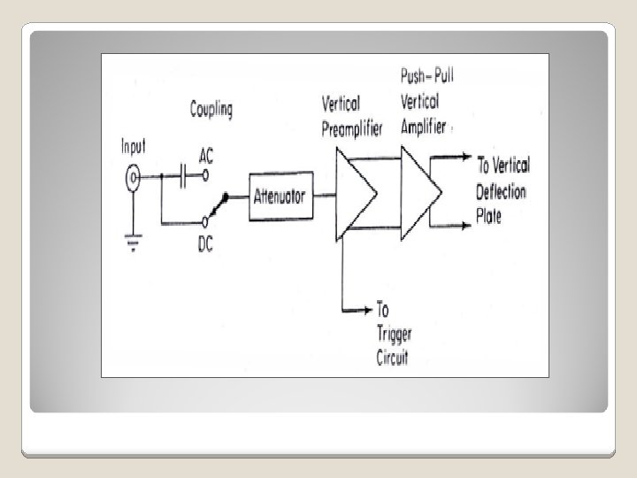
Vertical deflection system: * The function of the deflection system provides an amplified signal of the proper level to derive the vertical deflection plates without distorting the signal
* A general type oscilloscope can accept as low as a few millivolts/cm of deflection up to hundreds of volts using the built in attenuator and external probes.
Here , the attenuator sets the sensitivity of oscilloscope in the common sequence (1 -2 -5)
* the input attenuator provides the correct sequence attenuation while maintaining a constant input impedance , as well as maintaining the input impedance and attenuation over the frequency range for which the oscilloscope is designed
* Types of attenuators : :
A) • Uncompen sated attenuator
This type of attenuators (resistive divider att. ) is connected to an amplifier with 10 PF input capacitors the impedance changes based on the setting of attenuator , , therefore, the RC time constant and thus the frequency response of the amplifier are depending on the setting of the attenuator,
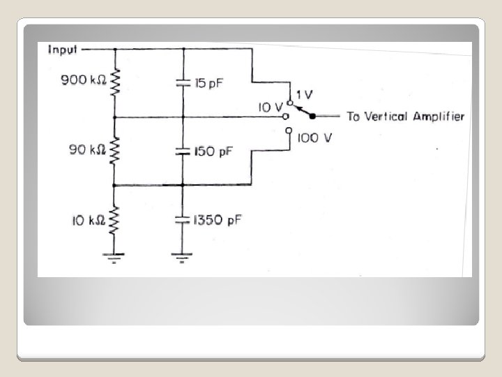
B) Compensated attenuator :
This kind has both resistance and capacitance voltage divider, noting that the capacitor voltage divider improves the high frequency response of the attenuator Practically, all oscilloscopes provide suitable input coupling capacitors
Note: this type of attenuator is needed to provide measurements of DC signal that are maybe viewed in the presence of the high DC voltage
* The input impedance of the oscilloscope is in general 1 M ohm shunted with(10 PF to 30 PF) * It is usually desirable (for high frequency oscilloscope)to have an input capacitance much less than(20 -30)PF and this achieved by the use of att. probes
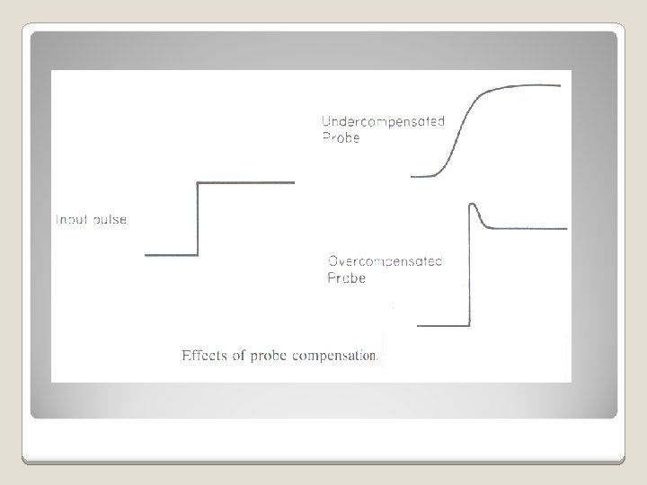
In the base of the probe at the oscilloscope connector, there is an adjustable capacitor. This capacitor is adjusted so that the ratio of the shunt capacitance to the series capacitance is exactly 10 to 1. The attenuator probe (usually called 10 -1 probe) provides approximately a 10 -1 reduction in the input capacitance. If the setting of the compensation is incorrect, then the result will be seen by observing the rise-time-pulse.
Horizontal system consist of : Time Base Generator (T. B) Triggering Circuit (T. C) Horizontal Amplifier (H. A)
H. D T. C T. B H. A
The time base controls the rate of which the beam is scanned The triggering circuit insures that the horizontal sweep starts at the same point of the vertical input signal
* This rate can be adjusted by the current (I) or the capacitance (C) ** The sweep generator is capable of low sweeps (20 µ s/Div – 50 ns/Div)
*** This sweep does not start until a triggering pulse is initiated
Most Oscilloscopes have a built in oscillator to trigger the beam when no input signal is present , so that one would know the base time, , Some oscilloscopes have two time base generator where one would trigger before the other
This advantage is applied in a situation where a signal with longer period is begun viewed but a small part of the signal is to be analyzed …
* The time base is used to sweep the electrons at a constant sweep from left to right across the screen ** And then quickly returns the beam to the left in time to begin in the next sweep *** The time base can be adjusted to the sweep time to the period of the signal
The sweep does not usually trigger for each cycle of the vertical input unless the sweep pulse roll off time is less than +ve period of the input …
Oscilloscope Probes *The goal of the oscilloscope is to display the signal as a function of time **To make the oscilloscope more useful device, , different types of probes maybe used ***(i. e. 11 ratio , 10 -1 ratio)
Current Probe : **This gives the oscilloscope the ability to measure the magnitude of the current with a frequency response from DC(0 Hz)- 50 MHz. *This device can be clamped around a wire carrying an electrical current without any physical connection with the probe.
The current sensor consists of a conventional transformer and a Hall-effect device.
Alternating current in the wire will induce voltage in the secondary winding by the transformer , any direct current will not appear at the current transformer secondary circuit, the direct current passing through the wire will cause the magnetic flux in the core to increase will effect the permeability of the material used for the core (this is undesirable)
To over come this problem: a Hall-effect sensor is used to provide a frequency response to the DC ,
A feedback system is arranged with an amplifier such that any magnetic field present in the Hall-effect device will cause the current to be induced in to the secondary winding to counteract the magnetic field induced in the wire being used in measurement.
Frequency determination:
Δ : Difference F=1/T • ( ΔT/T) • *360=ɵ V(t)= Asin(wt) =Asin(wt+ ɵ)
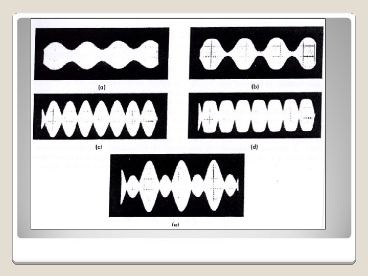
2 - determination of modulation characteristics : The oscilloscope can be used to measure the amount of amplitude modulation applied to a carrier for adjusting and trouble-shooting amplitude –modulated transmitters
To display the carrier the oscilloscope must be capable of covering the carrier frequency of the transmitter the horizontal sweep has only to cover the modulation frequency.
The modulation percentage can be determined from the wave form & is calculated as:
Modulation%= • ((A-B)/(A+B)) • *100% Where; A: is the peak of the modulate envelope & (B) is the minimum.
Note : In no case , , the amplitude modulation of the carrier wave exceed 100% the reason this should be avoided is based on (( carrier -cut-off)) The carrier in this case is actually completely gone, ,