Slope Deflection Method for the Analysis of Indeterminate


")


 may be written as:")
 relate the unknown moments applied to the")
")
: Equilibrium conditions Compatibility conditions")

 Solution 1. Draw the shear and moment diagrams for the beam shown")
")


, (b), (c), and (d):")

 Shearing Force & Bending Moment Digrams")
 Determine the internal moments at the supports of the beam shown in")
.")


 & (p) may then be")
 If end A in example (1) is simply supported, and by applying")

 for and substitute the values into equations")

- Slides: 33
Slope Deflection Method for the Analysis of Indeterminate beams By Assist Lect. Lubna Mohammed Abd
All structures must satisfy: Load-displacement relationship n Equilibrium of forces n Compatibility of displacements n
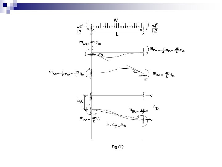
Using the principle of superposition by considering separately the moments developed at each support of a typical prismatic beam (AB) shown in Fig. 1(a) of a continuous beam, due to each of the displacements , , and the applied loads. Assume clockwise moments are +ive.
1. Assume ends A and B are fixed, i. , e. , the rotations. This means that we have to apply counterclockwise moment at end A and clockwise moment at end B due to the applied loads to cause zero rotation at each of ends A and B. Table (1) gives for different loading conditions.
Table (1)
2. Release end A against rotation at end A (rotates to its final position ) by applying clockwise moment while far end node B is held fixed as shown in Fig. 1. 3. Now, the clockwise moment - rotation relationship is:
4. The carry over moment at end B is: 5. In a similar manner, if end B of the beam rotates to its final position , while end A is held fixed. The clockwise moment – rotation relationship is:
6. The carry over moment at end A is: 7. If node B is displaced relative to as shown in Fig. (1), so that the cord of the member rotates clockwise i. , e. , positive displacement and yet both ends do not rotate, then equal but anticlockwise moments are developed in the member as shown in the figure.
Slope-Deflection Equation Load-displacement relationship If the end moments due to each displacement and the loading are added together, the resultant moments at the ends may then be written as:
For prismatic beam element, equation (1) may be written as:
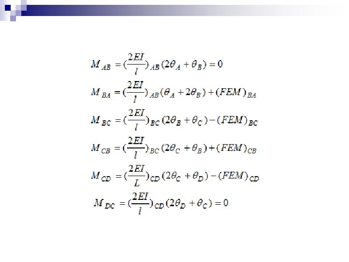
The slope deflection equations (1 or 2) relate the unknown moments applied to the nodes to the displacements of the nodes for any span of the structure. To summarize application of the slopedeflection equations, consider the continuous beam shown in Fig. (2) which has four degrees of freedom. Now equation (2) can be applied to each of the three spans.
Fig. (2)
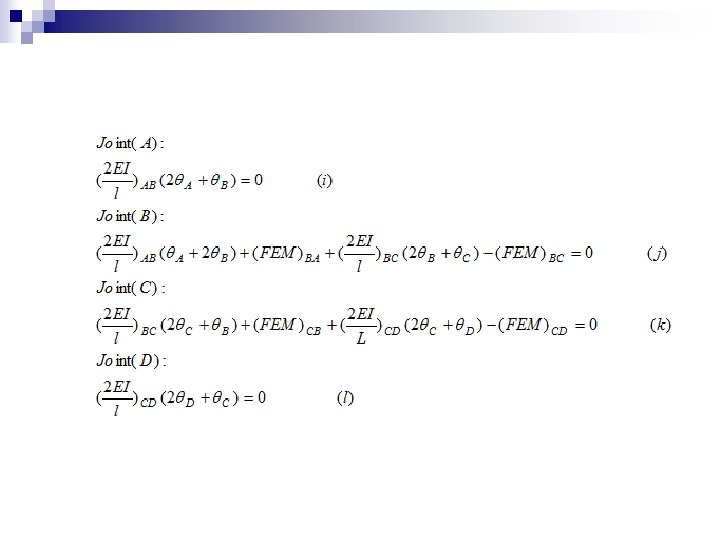
From Fig. (2): Equilibrium conditions Compatibility conditions
n n n These equations would involve the four unknown rotations. Solving for these four unknown rotations. It may be noted that there is no relative deflection between the supports, so that The values of the obtained rotations may then be substituted in to the slope deflection equations to determine the internal moments at the ends of each member. If any of the results are negative, they indicate counterclockwise rotation.
Example (1) Solution 1. Draw the shear and moment diagrams for the beam shown in Fig. (3). EI is constant. Using the formulas for the tabulated in Table (1) for the given loadings:
Fig. (3)
2. There are two slopes at B and C, i. , e. , are unknowns. Since end A is fixed, Also, since the supports do not settle, nor are they displaced up or down
Now, by applying the equilibrium conditions:
Substituting the computed values in to moment equations (a), (b), (c), and (d):
By considering the values of support moments and the applied loads, the support reactions may then be determined: RA = 8. 3625 k. N RB = 10. 2042 k. N RC = 1. 8333 k. N Shearing force and bending moment digrams are shown in Fig. (4).
Fig. (4) Shearing Force & Bending Moment Digrams
Example (2) Determine the internal moments at the supports of the beam shown in Fig. (5). The support at B is displaced (settles) 12 mm.
Solution 1. Two spans must be considered. FEMs are determined using Table (1).
2. Using equation 2:
3. Equilibrium condition:
n In order to obtained the rotations equations (n) & (p) may then be solved simultaneously, it may be noted that since A is fixed support. Thus, Substituting these values into equations (i to l) yields
Example (3) If end A in example (1) is simply supported, and by applying the compatibility condition, their will be three unknown rotations, Now,
Applying the equilibrium conditions:
By solving equations (1, 2 & 3) for and substitute the values into equations (a, b, c, d):
Shearing force and bending moment diagrams are shown in the following figure.