Sim Worx Engineering Research Development Filling the Gap

- Slides: 45
Sim. Worx Engineering, Research & Development
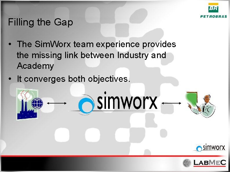
Filling the Gap • The Sim. Worx team experience provides the missing link between Industry and Academy • It converges both objectives.
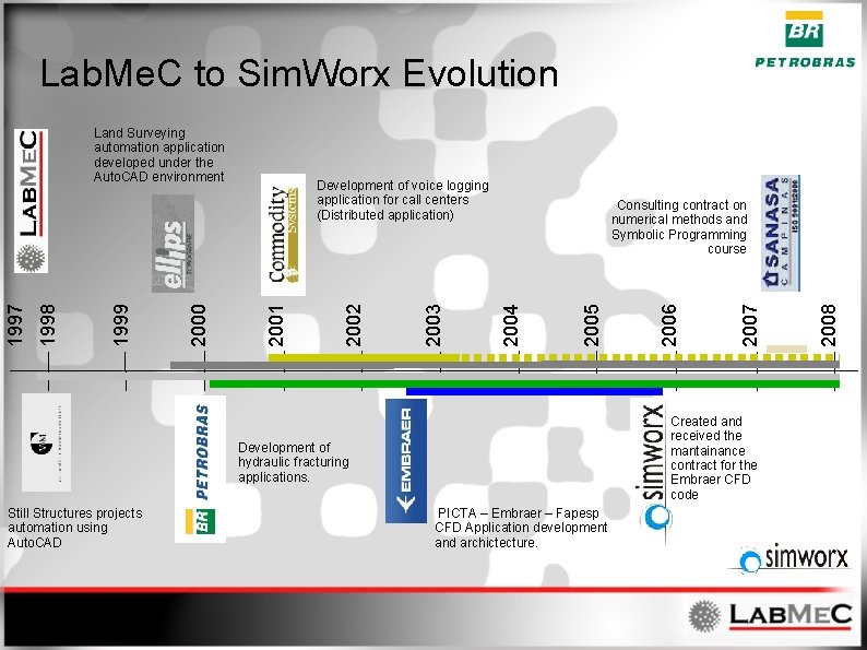
Lab. Me. C to Sim. Worx Evolution PICTA – Embraer – Fapesp CFD Application development and archictecture. 2008 2007 Created and received the mantainance contract for the Embraer CFD code Development of hydraulic fracturing applications. Still Structures projects automation using Auto. CAD 2006 2005 Consulting contract on numerical methods and Symbolic Programming course 2004 2003 2002 Development of voice logging application for call centers (Distributed application) 2001 2000 1999 1998 1997 Land Surveying automation application developed under the Auto. CAD environment
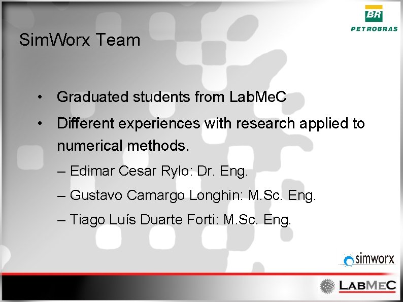
Sim. Worx Team • Graduated students from Lab. Me. C • Different experiences with research applied to numerical methods. – Edimar Cesar Rylo: Dr. Eng. – Gustavo Camargo Longhin: M. Sc. Eng. – Tiago Luís Duarte Forti: M. Sc. Eng.
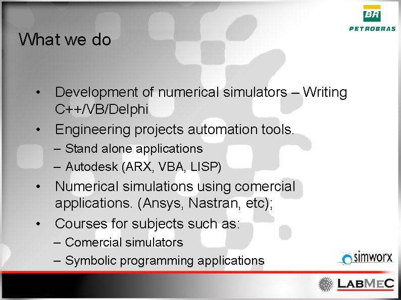
What we do • • Development of numerical simulators – Writing C++/VB/Delphi Engineering projects automation tools. – Stand alone applications – Autodesk (ARX, VBA, LISP) • • Numerical simulations using comercial applications. (Ansys, Nastran, etc); Courses for subjects such as: – Comercial simulators – Symbolic programming applications
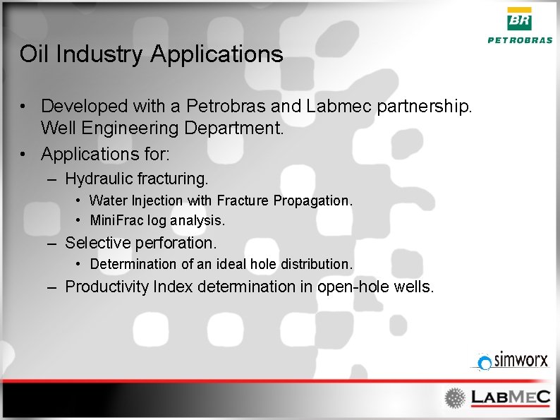
Oil Industry Applications • Developed with a Petrobras and Labmec partnership. Well Engineering Department. • Applications for: – Hydraulic fracturing. • Water Injection with Fracture Propagation. • Mini. Frac log analysis. – Selective perforation. • Determination of an ideal hole distribution. – Productivity Index determination in open-hole wells.
The Sim. Worx / Lab. Me. C Implementation Models • Developed according to Object Oriented Philosophy – Easy mantainance and extension. – It better addresses complexities. – Allows for code reusability. • Developed in C++ – Increases kernel performance. • Extensive use of Components. – Proprietary. – Developed in house.
Hydraulic Fracturing Applications • The SP 3 D application – Started development back in 2002. – A CENPES and Lab. Me. C combined effort. – Served as the base project for the Lab. Me. C CENPES long relationship. • The Propag application – Still evolving and incorporating new models / technologies. – A mantainance contract exists to support the necessary evolution.
The Propag Application • Numerical Simulator for: – Water injection with fracture propagation. • Its numerical model contemplates: – Formation’s Mechanical Behavior. – The flow of water through the porous medium. – The flow of water through the fracture opening. • Developed in C++. • Based on Object Oriented Techiniques.
The Propag Application • • Runs on regular PCs. Requires regular computational resources. Runs on Windows environment. Has an intuitive user interface with: – Reports. – Charts. • Developed as MDI (Multi-Document Interface). – Inproves data analysis. – Software Industry consolidated feature.
The Propag Formulation • The numerical kernel of Propag. – Incorporates lots of different models. – Evolves based on Petrobras requirements. – Evolves according to availability of new technologies.
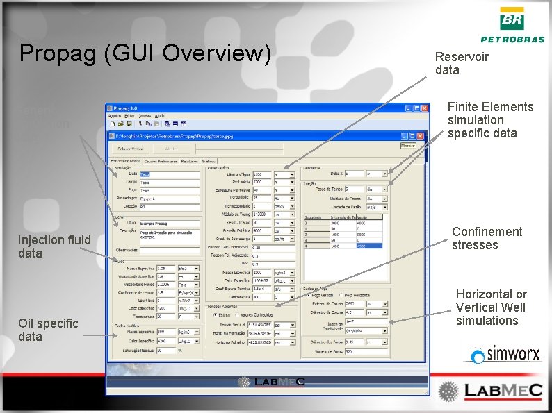
Propag (GUI Overview) Generic simulation data Injection fluid data Oil specific data Reservoir data Finite Elements simulation specific data Confinement stresses Horizontal or Vertical Well simulations
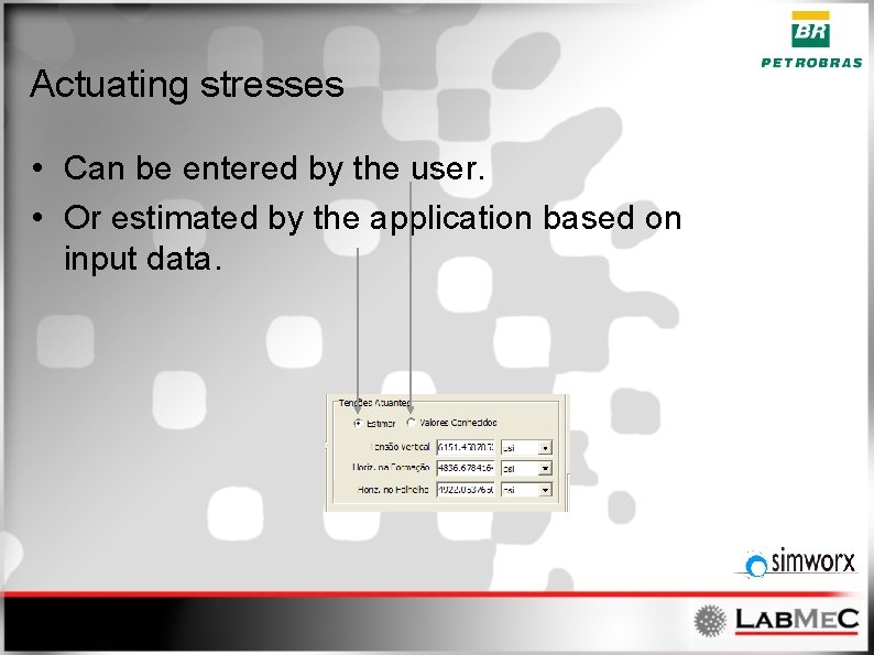
Actuating stresses • Can be entered by the user. • Or estimated by the application based on input data.
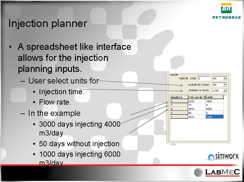
Injection planner • A spreadsheet like interface allows for the injection planning inputs. – User select units for • Injection time. • Flow rate. – In the example • 3000 days injecting 4000 m 3/day • 50 days without injection • 1000 days injecting 6000 m 3/day • . . .
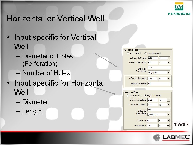
Horizontal or Vertical Well • Input specific for Vertical Well – Diameter of Holes (Perforation) – Number of Holes • Input specific for Horizontal Well – Diameter – Length
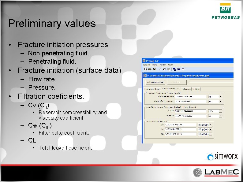
Preliminary values • Fracture initiation pressures – Non penetrating fluid. – Penetrating fluid. • Fracture initiation (surface data) – Flow rate. – Pressure. • Filtration coeficients. – Cv (CII) • Reservoir compressibility and viscosity coefficient. – Cw (CIII) • Filter cake coefficient. – CL • Total leakoff coefficient.
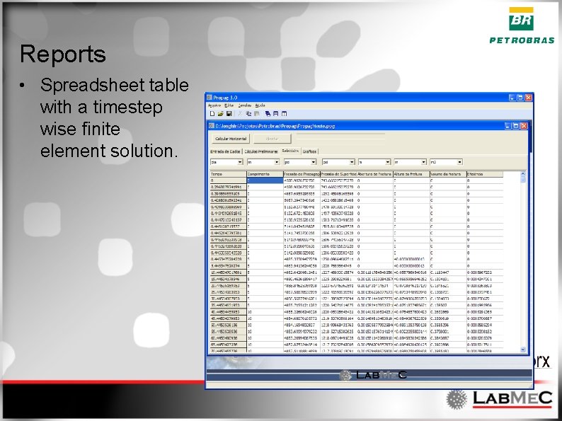
Reports • Spreadsheet table with a timestep wise finite element solution.
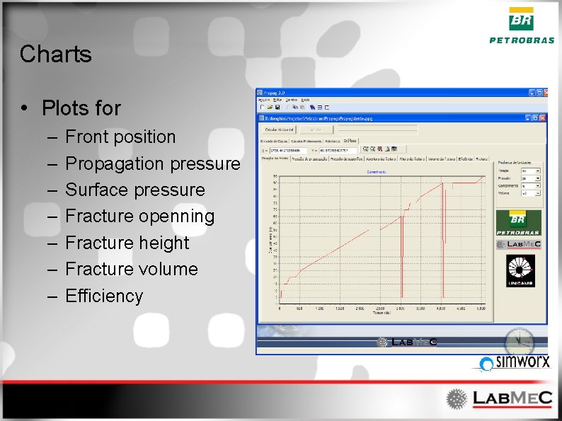
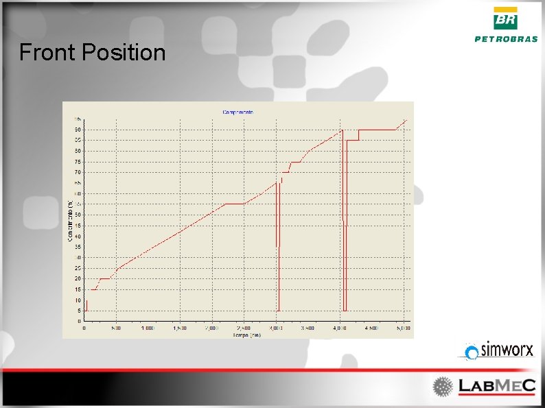
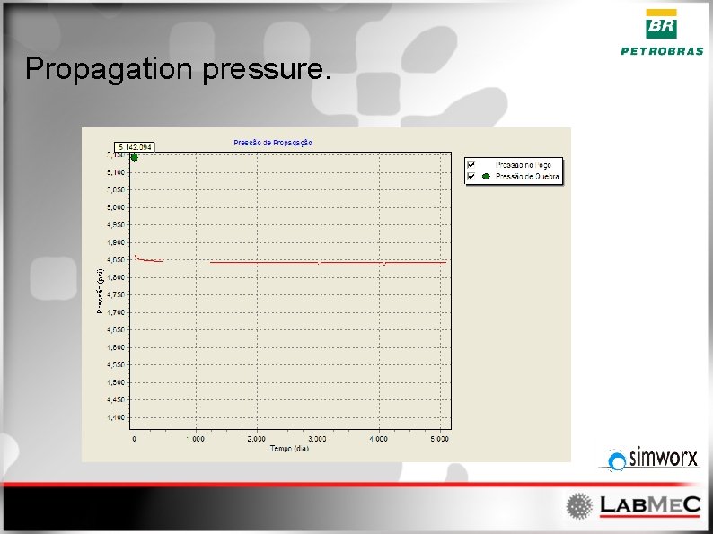
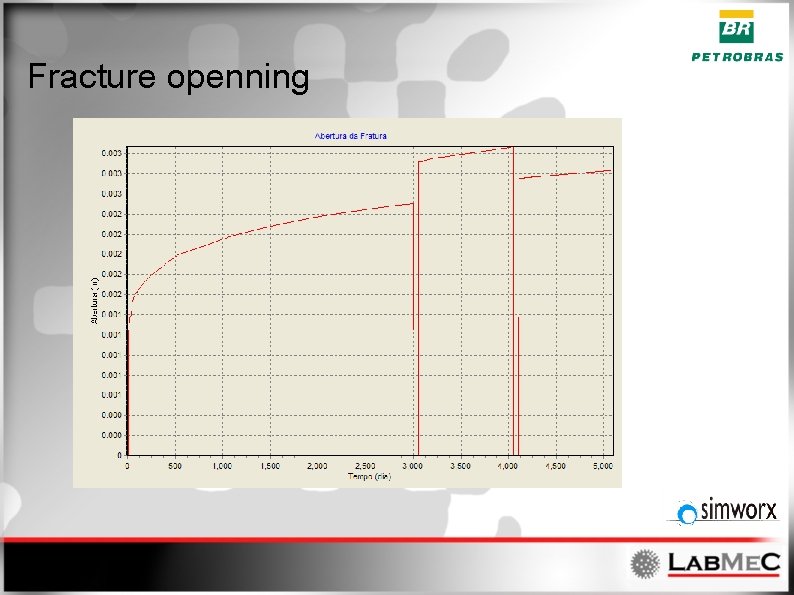
Charts • Plots for – – – – Front position Propagation pressure Surface pressure Fracture openning Fracture height Fracture volume Efficiency
Front Position
Propagation pressure.
Fracture openning
Data exchange features • Exports charts. – Bitmaps (figures) – MS Excel spreadsheets – ASCII text.
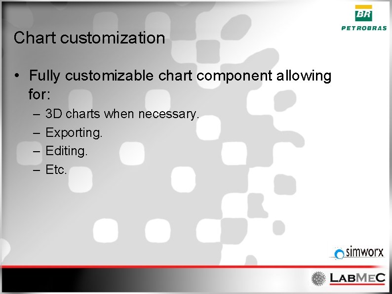
Chart customization • Fully customizable chart component allowing for: – – 3 D charts when necessary. Exporting. Editing. Etc.
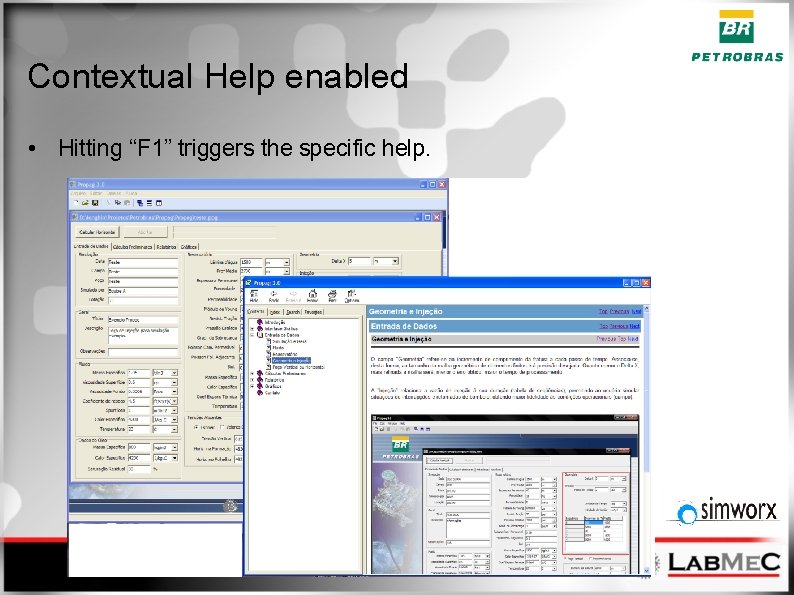
Contextual Help enabled • Hitting “F 1” triggers the specific help.
Future work • • • Translations Incorporate new formulations. Vapor Injection Horizontal Stresses anisotropy Etc. . .
Pro. Div Application • Application for Design and Analysis of Inflow Control by Unevenly Distributed Perforation. – Contemplates • Producion • Injection • Acidization
Pro. Div background • Complyes with the Lab. Me. C / Sim. Worx development model. • Based on the same computational frameworks of Pro. Pag. • Developed according to Object Oriented Philosophy. • Written in C++.
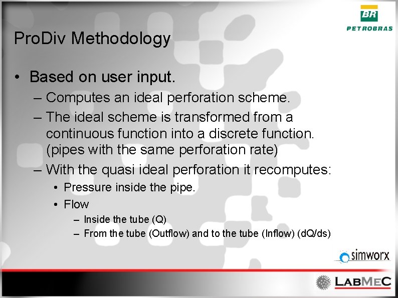
Pro. Div Methodology • Based on user input. – Computes an ideal perforation scheme. – The ideal scheme is transformed from a continuous function into a discrete function. (pipes with the same perforation rate) – With the quasi ideal perforation it recomputes: • Pressure inside the pipe. • Flow – Inside the tube (Q) – From the tube (Outflow) and to the tube (Inflow) (d. Q/ds)
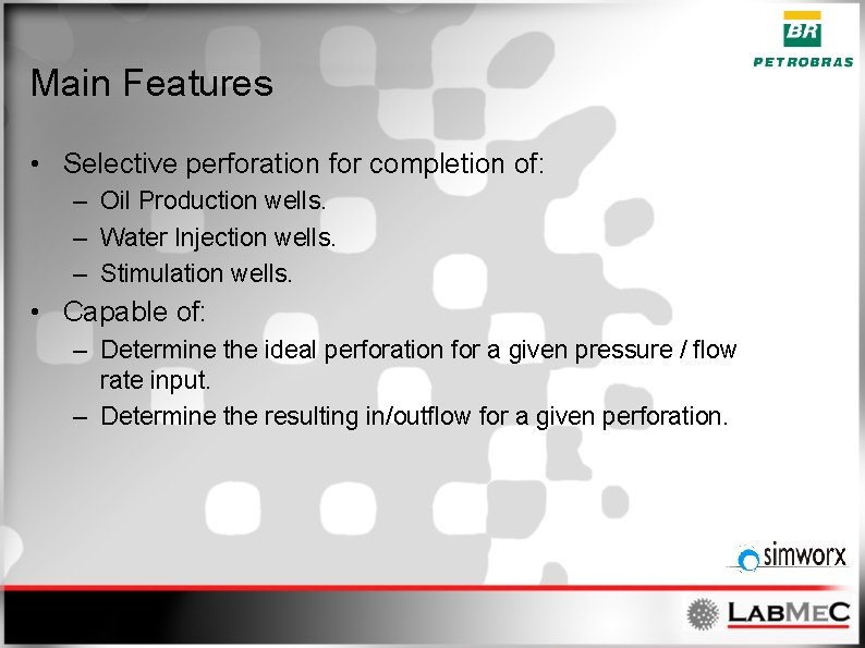
Main Features • Selective perforation for completion of: – Oil Production wells. – Water Injection wells. – Stimulation wells. • Capable of: – Determine the ideal perforation for a given pressure / flow rate input. – Determine the resulting in/outflow for a given perforation.
Main Features • The adopted perforation rate can be edited by the user – Check existing configurations. – Check possible behaviors for different scenarios. – Fine tunning according to user experience. • With the same perforation, the user can change the operation flow rate and check the behavior with that perforation scheme.
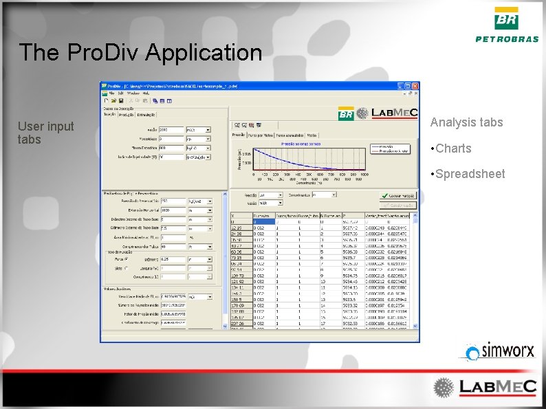
The Pro. Div Application User input tabs Analysis tabs • Charts • Spreadsheet
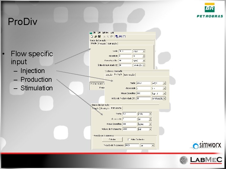
Pro. Div • Flow specific input – Injection – Production – Stimulation
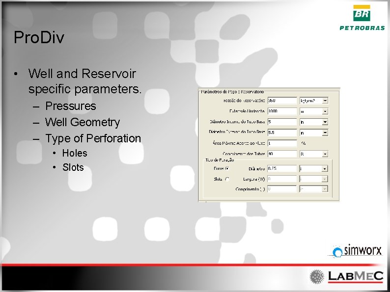
Pro. Div • Well and Reservoir specific parameters. – Pressures – Well Geometry – Type of Perforation • Holes • Slots
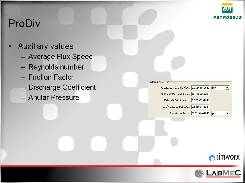
Pro. Div • Auxiliary values – – – Average Flux Speed Reynolds number Friction Factor Discharge Coefficient Anular Pressure
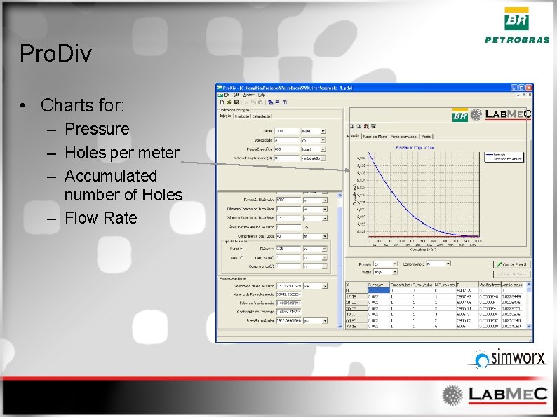
Pro. Div • Charts for: – Pressure – Holes per meter – Accumulated number of Holes – Flow Rate
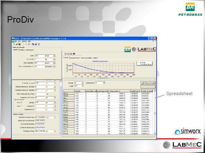
Pro. Div Spreadsheet
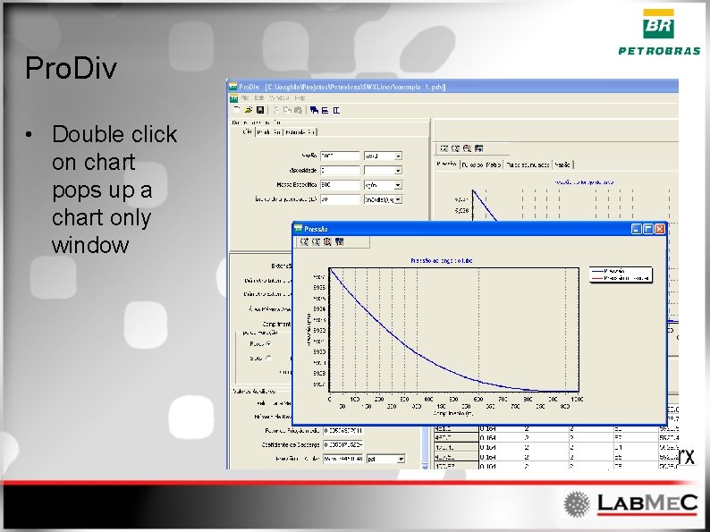
Pro. Div • Double click on chart pops up a chart only window
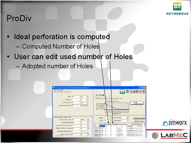
Pro. Div • Ideal perforation is computed – Computed Number of Holes • User can edit used number of Holes – Adopted number of Holes
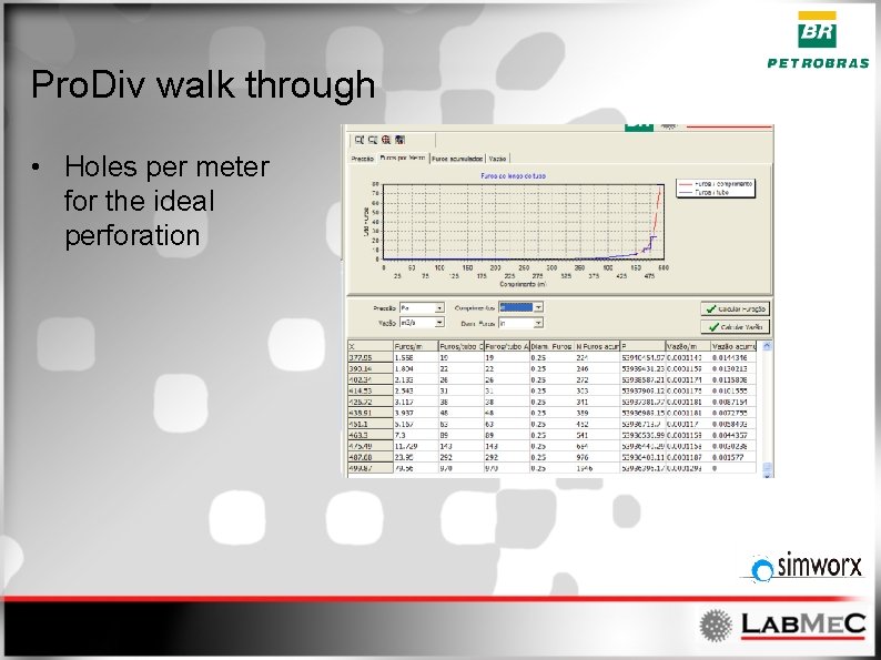
Pro. Div walk through • Holes per meter for the ideal perforation
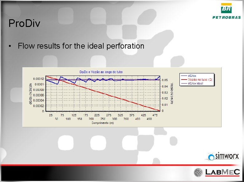
Pro. Div • Flow results for the ideal perforation
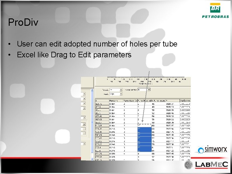
Pro. Div • User can edit adopted number of holes per tube • Excel like Drag to Edit parameters
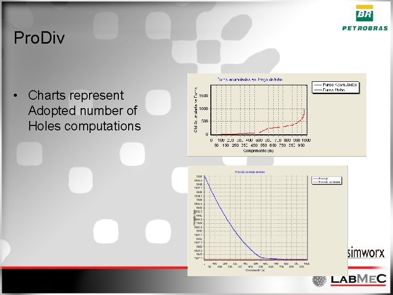
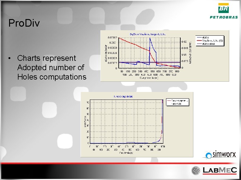
Pro. Div • Charts represent Adopted number of Holes computations
Pro. Div • Charts represent Adopted number of Holes computations
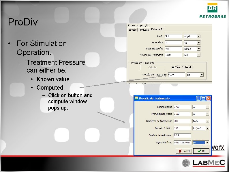
Pro. Div • For Stimulation Operation. – Treatment Pressure can either be: • Known value • Computed – Click on button and compute window pops up.
Future works • • Pressure and Permeability anisotropy Editing functionalities Translations Etc. . .