RF Techniques and Developments at SSRF Wenzhi Zhang
- Slides: 42
RF Techniques and Developments at SSRF Wenzhi Zhang On behalf of RF group Dec. 2013
Outline FIntroduction of RF System at SSRF FOperation status of RF FR&D of SRF at SSRF 2021/3/6
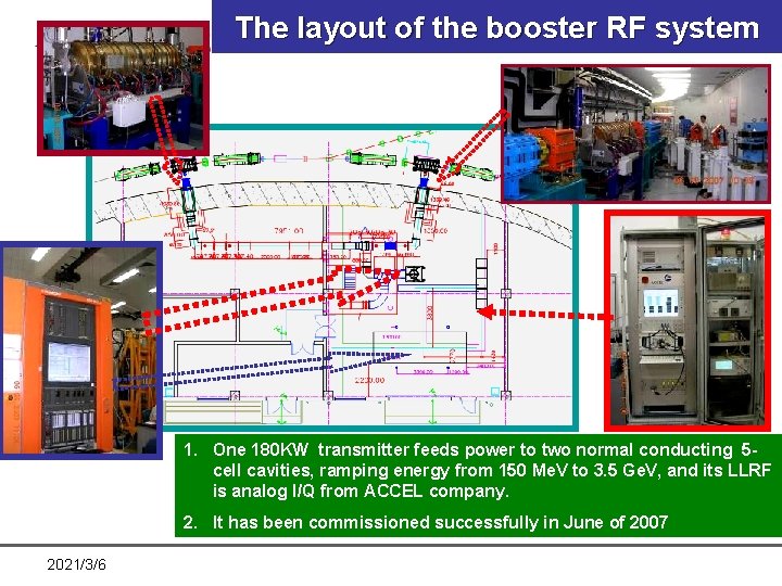
The layout of the booster RF system 1. One 180 KW transmitter feeds power to two normal conducting 5 cell cavities, ramping energy from 150 Me. V to 3. 5 Ge. V, and its LLRF is analog I/Q from ACCEL company. 2. It has been commissioned successfully in June of 2007 2021/3/6
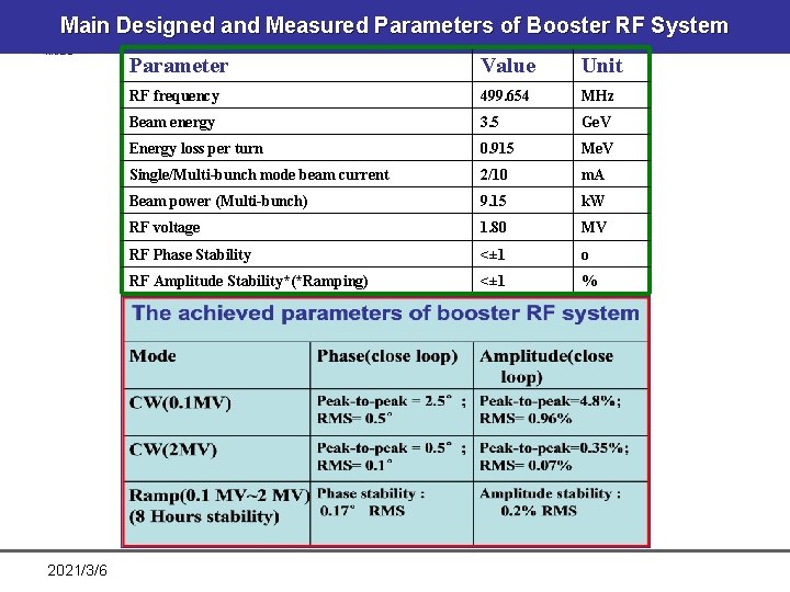
Main Designed and Measured Parameters of Booster RF System 2021/3/6 Parameter Value Unit RF frequency 499. 654 MHz Beam energy 3. 5 Ge. V Energy loss per turn 0. 915 Me. V Single/Multi-bunch mode beam current 2/10 m. A Beam power (Multi-bunch) 9. 15 k. W RF voltage 1. 80 MV RF Phase Stability <± 1 o RF Amplitude Stability*(*Ramping) <± 1 %
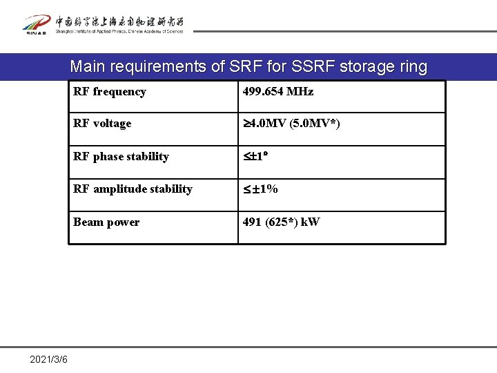
Main requirements of SRF for SSRF storage ring 2021/3/6 RF frequency 499. 654 MHz RF voltage 4. 0 MV (5. 0 MV*) RF phase stability 1 RF amplitude stability 1% Beam power 491 (625*) k. W
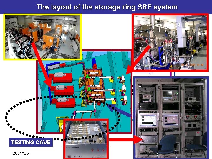
The layout of the storage ring SRF system 1 TESTING CAVE 2021/3/6 2 3
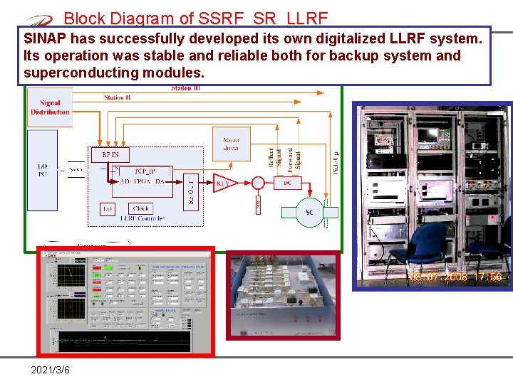
Block Diagram of SSRF_SR_LLRF SINAP has successfully developed its own digitalized LLRF system. Its operation was stable and reliable both for backup system and superconducting modules. 2021/3/6
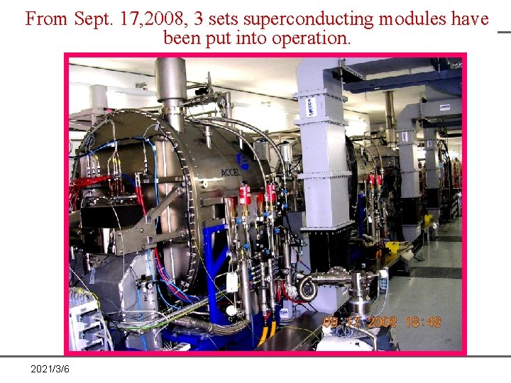
From Sept. 17, 2008, 3 sets superconducting modules have been put into operation. 2021/3/6
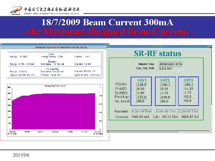
18/7/2009 Beam Current 300 m. A --the Maximum Designed Beam Current-- 2021/3/6
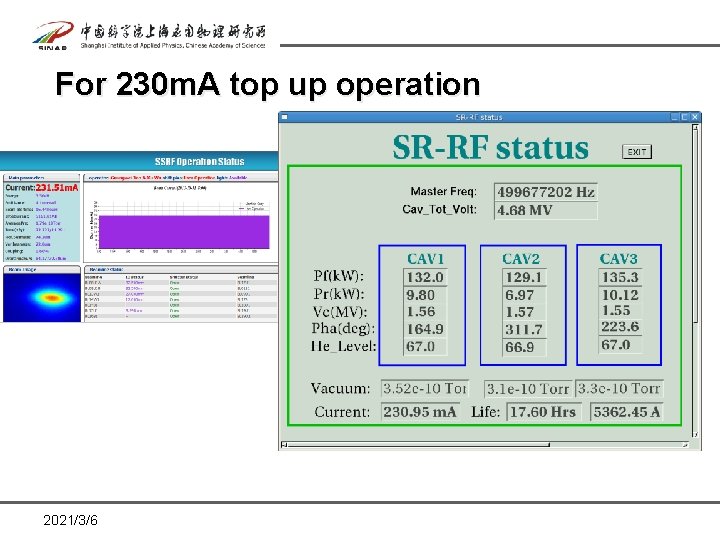
For 230 m. A top up operation 2021/3/6
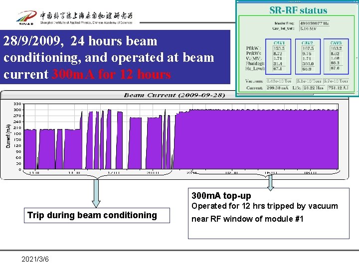
28/9/2009, 24 hours beam conditioning, and operated at beam current 300 m. A for 12 hours 300 m. A top-up Operated for 12 hrs tripped by vacuum Trip during beam conditioning 2021/3/6 near RF window of module #1
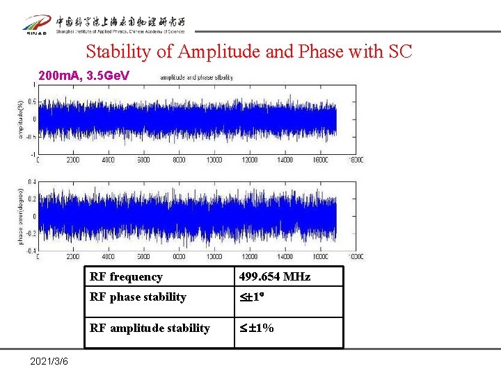
Stability of Amplitude and Phase with SC 200 m. A, 3. 5 Ge. V 2021/3/6 RF frequency 499. 654 MHz RF phase stability 1 RF amplitude stability 1%
Contents FBrief Introduction of SSRF FRF System of SSRF FOperation of RF FR&D of SRF at SINAP 2021/3/6
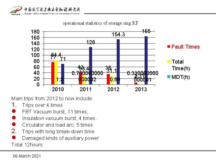
operational statistics of storage ring RF 180 160 140 120 100 80 60 40 20 0 154. 3 128 Fault Times 84. 4 77 71 1. 2 2010 43 36 33. 4 0. 760000000 31. 1 0. 89 000002 2011 Main trips from 2012 to now include: 1. Trips over 4 times l FBT Vacuum burst, 11 times; l Insulation vacuum burst, 4 times. l Circulator and load arc, 5 times 2. Trips with long break-down time l Damaged kinds of auxiliary power Total 12 hours 06 March 2021 165 2012 0. 330000000 2. 31 7 000001 2013 Total Time(h) MDT(h)
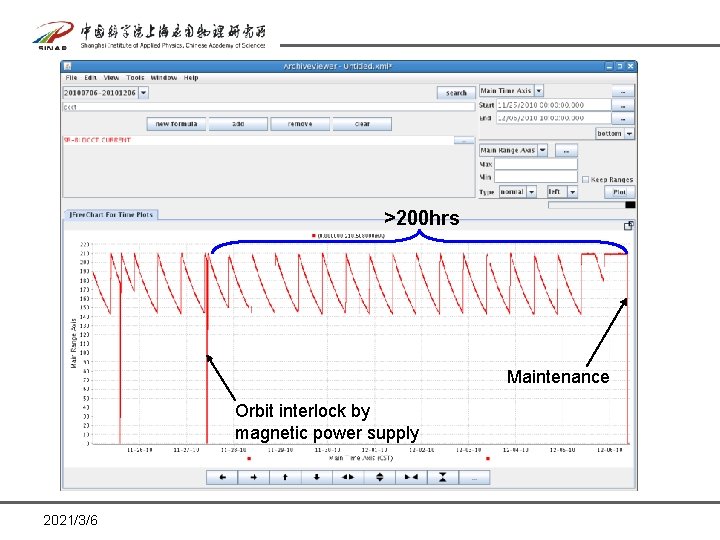
>200 hrs Maintenance Orbit interlock by magnetic power supply 2021/3/6
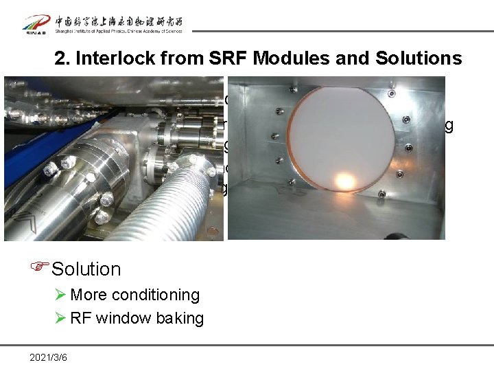
2. Interlock from SRF Modules and Solutions FBeam trip by RF window out-gassing Ø The module was ever exposed to atmosphere during SAT due to the leakage around pump-out box; Ø Water mark was found around the window after RF window baking during SAT FSolution Ø More conditioning Ø RF window baking 2021/3/6
Cavity Processing FConditioning of the RF window with up to 100 k. W RF power at about 100 k. Hz off resonance again under the LLRF control. FChange the phase of standing wave to increase the forward power while keeping the cavity voltage at 1. 5 MV with frequency loop and IQ loop of LLRF are closed. FConditioning of the RF window with beam current. One method is to increase the beam current by a slow increase, the other is to adjust the accelerating phase of the cavities slowly while keeping the same beam current. 2021/3/6
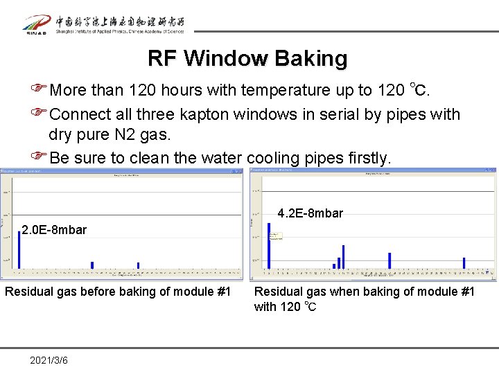
RF Window Baking FMore than 120 hours with temperature up to 120 ℃. FConnect all three kapton windows in serial by pipes with dry pure N 2 gas. FBe sure to clean the water cooling pipes firstly. 4. 2 E-8 mbar 2. 0 E-8 mbar Residual gas before baking of module #1 2021/3/6 Residual gas when baking of module #1 with 120 ℃
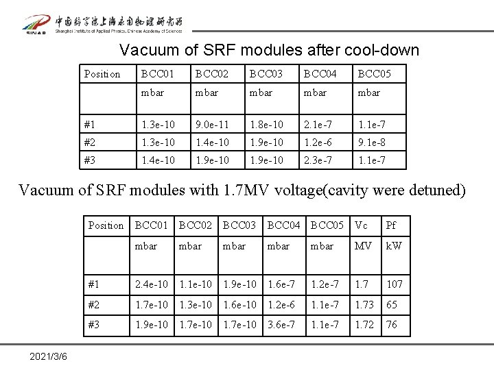
Vacuum of SRF modules after cool-down Position BCC 01 BCC 02 BCC 03 BCC 04 BCC 05 mbar mbar #1 1. 3 e-10 9. 0 e-11 1. 8 e-10 2. 1 e-7 1. 1 e-7 #2 1. 3 e-10 1. 4 e-10 1. 9 e-10 1. 2 e-6 9. 1 e-8 #3 1. 4 e-10 1. 9 e-10 2. 3 e-7 1. 1 e-7 Vacuum of SRF modules with 1. 7 MV voltage(cavity were detuned) Position BCC 01 mbar 2021/3/6 BCC 02 BCC 03 BCC 04 BCC 05 Vc Pf mbar MV k. W #1 2. 4 e-10 1. 1 e-10 1. 9 e-10 1. 6 e-7 1. 2 e-7 1. 7 107 #2 1. 7 e-10 1. 3 e-10 1. 6 e-10 1. 2 e-6 1. 1 e-7 1. 73 65 #3 1. 9 e-10 1. 7 e-10 3. 6 e-7 1. 1 e-7 1. 72 76
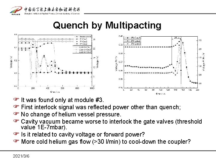
Quench by Multipacting F It was found only at module #3. F First interlock signal was reflected power other than quench; F No change of helium vessel pressure. F Cavity vacuum became worse to interlock the gate valves (threshold value 1 E-7 mbar). F Is it related to cavity voltage or forward power? F More cold helium gas flow (>30 l/min) to cool-down the coupler? 2021/3/6
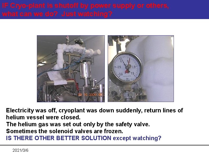
IF Cryo-plant is shutoff by power supply or others, what can we do? Just watching? Electricity was off, cryoplant was down suddenly, return lines of helium vessel were closed. The helium gas was set out only by the safety valve. Sometimes the solenoid valves are frozen. IS THERE OTHER BETTER SOLUTION except watching? 2021/3/6
Warm up of module FThe helium gas was set out through warm return line other than cold return line; FWarm-up of module many times, will it damage the insulation vacuum? FFor SSRF, the compressor has to be maintenance every year in the summer, thus SRF modules have to warm-up. Is there some solutions? FA spare compressor? 2021/3/6
Cool down of SRF modules FThree modules were cool-down in the same time with cooling speed 10 K~15 K/hour; FWhen temperature is around 120 K, increase the cooling speed; FCarefully switch the warm return valve and cold return valve after the module is cooled. 2021/3/6
Contents FBrief Introduction of SSRF FRF System of SSRF FOperation of RF FR&D of SRF at SINAP 2021/3/6
ØSRF Lab in SINAP Ø Cavity R&D Ø Surface Processing Ø Vertical test facility 2021/3/6
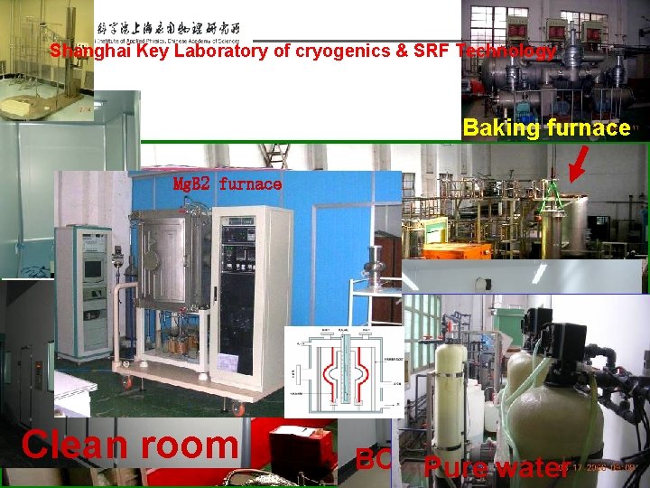
Shanghai Key Laboratory of cryogenics & SRF Technology Baking furnace Mg. B 2 furnace Clean room 2021/3/6 BCP Lab Pure water
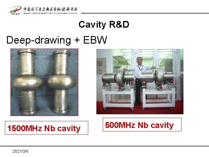
Cavity R&D Deep-drawing + EBW 1500 MHz Nb cavity 2021/3/6 500 MHz Nb cavity
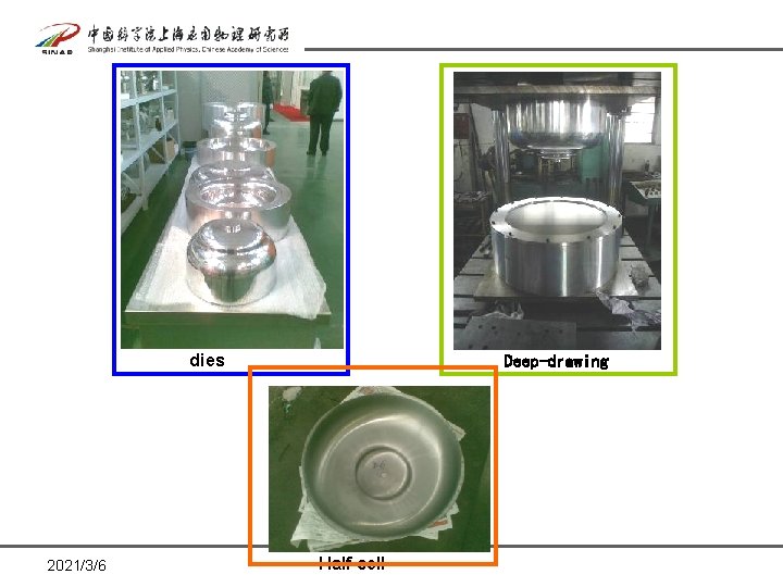
dies 2021/3/6 Deep-drawing Half cell
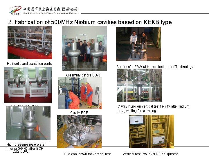
2. Fabrication of 500 MHz Niobium cavities based on KEKB type Half cells and transition parts Successful EBW at Harbin Institute of Technology Assembly before EBW Cavities in SCLab Cavity BCP Cavity hung on vertical test facility after Indium seal, waiting for pumping High pressure pure water rinsing (HPR) after BCP 2021/3/6 LHe cool-down for vertical test low level RF equipment
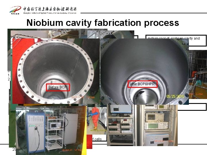
Niobium cavity fabrication process material Nb sheet - Ningxia Orient Tantalum industry CO. LTD surface preparation includes mechanical grinding, BCP, HPR, etc indium seal of niobium cavity and couplers in clean room t=3 mm. RRR=300 forming technique. Spinning or deep drawing. RF performance measurement of niobium cavity at room temperature Evacuation and Leak check at room temperature Deep drawing 1. Less reduction of the thickness 2. Smoother surface design and fabrication of Dies and Before BCP female dies preparation for vertical test includes electric beam welding. vacuum isafter BCP&HPR assembly to vertical test platform, better than 5 E-5 torr cool-down, RF power source, LLRF Niobium sheets check deep drawing on hydraulic machine Max. pressure 20 MPa fabrication of beam pipes and Nb-Ti flanges trimming of half cell pre-processing of half cell frequency measurement of 2 half cells 2021/3/6 vertical test at 4. 2 K
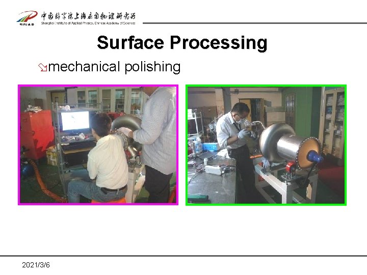
Surface Processing ømechanical polishing 2021/3/6
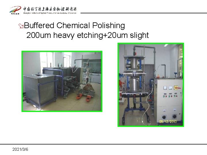
øBuffered Chemical Polishing 200 um heavy etching+20 um slight 2021/3/6
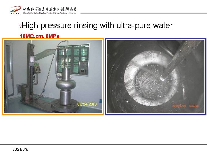
øHigh pressure rinsing with ultra-pure water 18 MΩ. cm, 8 MPa 2021/3/6
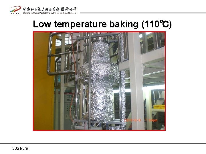
Low temperature baking (110℃) 2021/3/6
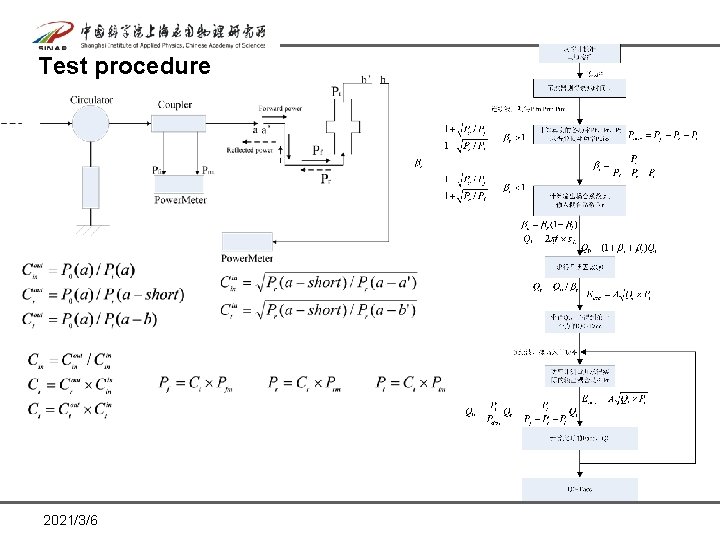
Test procedure 2021/3/6
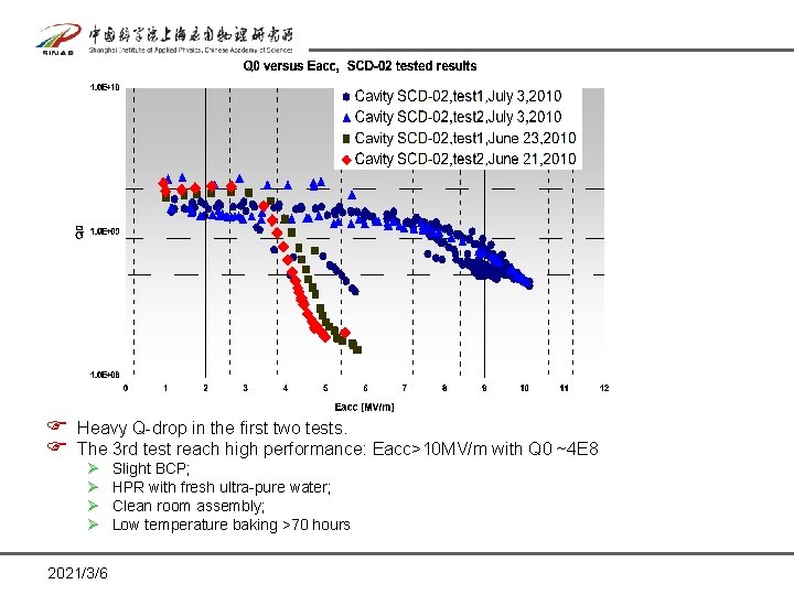
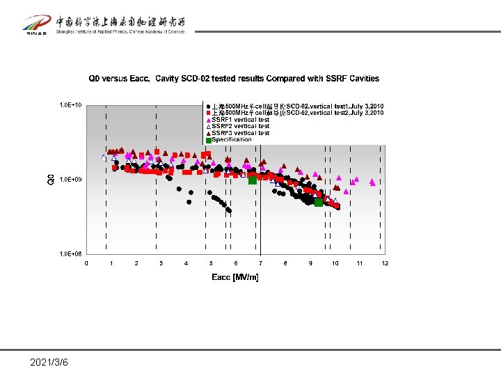
F Heavy Q-drop in the first two tests. F The 3 rd test reach high performance: Eacc>10 MV/m with Q 0 ~4 E 8 Ø Ø 2021/3/6 Slight BCP; HPR with fresh ultra-pure water; Clean room assembly; Low temperature baking >70 hours
2021/3/6
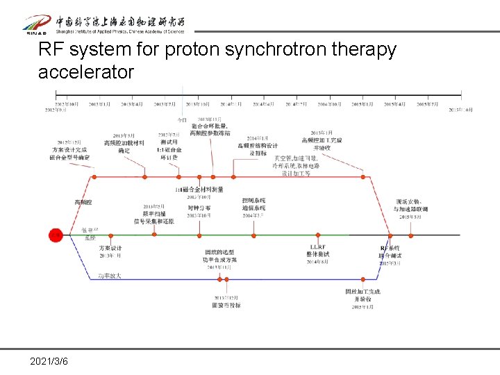
RF system for proton synchrotron therapy accelerator 2021/3/6
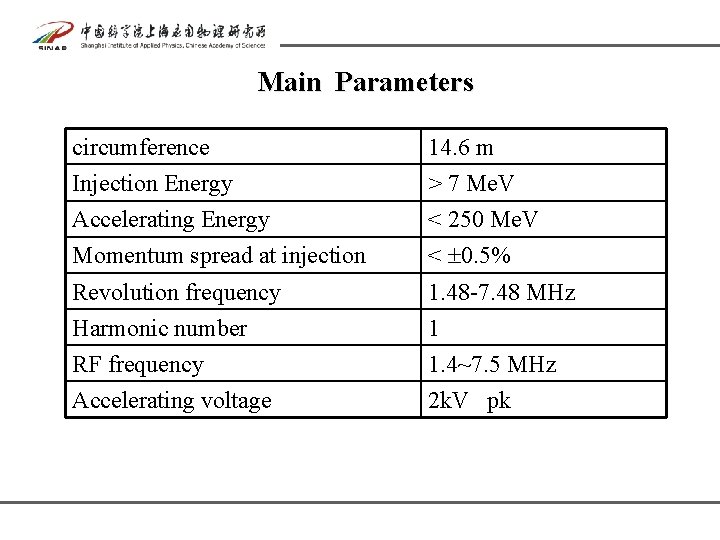
Main Parameters circumference 14. 6 m Injection Energy > 7 Me. V Accelerating Energy < 250 Me. V Momentum spread at injection < 0. 5% Revolution frequency 1. 48 -7. 48 MHz Harmonic number 1 RF frequency 1. 4~7. 5 MHz Accelerating voltage 2 k. V pk
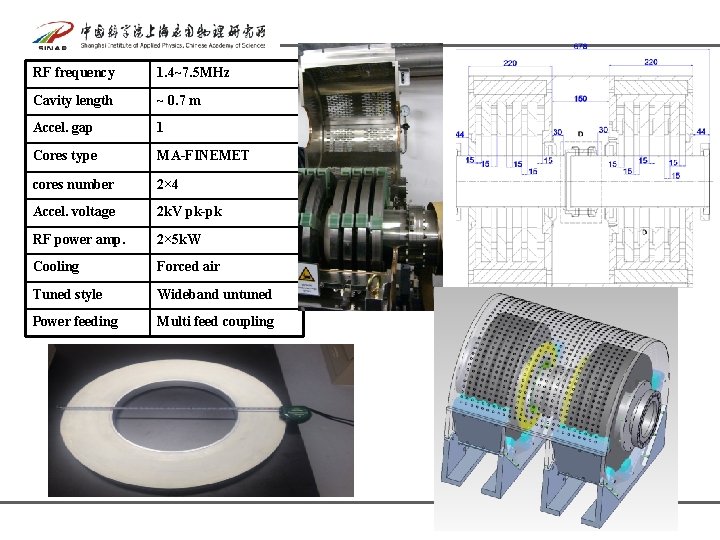
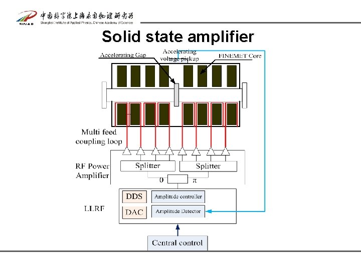
RF frequency 1. 4~7. 5 MHz Cavity length ~ 0. 7 m Accel. gap 1 Cores type MA-FINEMET cores number 2× 4 Accel. voltage 2 k. V pk-pk RF power amp. 2× 5 k. W Cooling Forced air Tuned style Wideband untuned Power feeding Multi feed coupling
Solid state amplifier
thanks 2021/3/6