Present Status of Shanghai Light Source SSRF Dekang
 Dekang LIU 2004/12/8")


: An intermediate energy 3 rd generation light source;")


 Bending Magnet (made in IHEP, Beijing)")
 Sextupole Magnet Made in CUSTC, Hefei")


 2.")


Analog to digital control mode ( 20 years ago)")
Distributed control system for PS (before 10 years) This method have been used")
SNS project PS control Fiber VME DC Power control 100 Khz Inject")


")


- Slides: 67
Present Status of Shanghai Light Source (SSRF) Dekang LIU 2004/12/8
A. Status of SSRF &Overview of the project progress & SSRF Design Optimization & Project Budget and Schedule B. Status of I & C for SSRF * Status of Control System * Status of Instrumentation
The SSRF project proposal was officially approved by the Chinese central government in January 2004!
Overview of the Project Progress
q. SSRF (Shanghai Synchrotron Radiation Facility): An intermediate energy 3 rd generation light source; q. The SSRF will be located in Shanghai Zhang-Jiang High Tech Park (Pudong new development district); n. The SSRF site occupies a area of 600 m 300 m n. About 25 km from Pudong international airport n. Close to Subway and magnetic leveled train line n. Convenient area to access the Shanghai down town
BEPCII/IHEP PLS Spring-8 PF Hefei LS TLS INDUSII SSRF/SINAP
Site of SSRF Pudong Airport Hongjiao Magnetic leveled train Airport 35 Km/7 minits 430 km/h Max
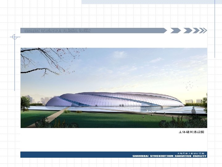
An Architect’s-eye of the SSRF Layout
Layout of SSRF 600 m 300 m
Brief History of the SSRF Project q. Dec. 1993: Three Chinese scientists proposed formally to central government to build a third generation light source; q. March 1995: The Chinese Academy of Sciences and the Shanghai municipal government made a joint proposal to construct the SSRF in Shanghai; q. June 1997 and March 1998: The state science and technology leading group and the state planning committee approved the SSRF R&D program; q. Jan. 1999~March, 2001: The SSRF R&D with budget of 80 M Yuan was being performed; q. Jan. 2004: The SSRF project was finally approved
q. About 10 year’s efforts to get this light source project approved; q. There are still one more project steps before performing the groundbreaking this year; n. Project feasibility study report review approval At July of 2004 n. Project approval detailed design study report review and
Hardware Prototype in Pre-R/D (1999 -2001) Bending Magnet (made in IHEP, Beijing)
Quadrupole Magnet (Made in Kelin, Shanghai) Sextupole Magnet Made in CUSTC, Hefei
Bending Magnet Power Supply 500 A/100 V, 1 10 5/24 hrs
6 m Antechamber Section
Kicker Magnet and Its Pulser 4 s half-sine-wave 0. 12 T peak field jitter time < 6. 5 ns
Low Level RF Control System
High Power RF System 500 MHz, 180 k. W CW RF local control station
BPM And Its Mapping System 2 m resolution Timing System
Evolution of the SSRF Designs q There have been 4 main SSRF design versions since 1996, and the SSRF has been evolved to a high performance and cost-effective light source for the past 8 years, which includes: n Upgraded the SSRF storage ring energy from 2. 2 Ge. V to 3. 5 Ge. V; n Optimized the storage ring with high flexibility, low emittance and high beam orbit stability; n Optimized the SSRF complex operating with top-up injection modes; n …
1996 2001 1998 2003
SSRF Accelerator complex q 100 Me. V Electron Linac q 3. 5 Ge. V Booster q 3. 5 Ge. V Storage Ring q Beam Line and Experimental stations
The SSRF Design Evolution Design Version 1996 1998 2001 2003 Energy (Ge. V) 2. 2 (2. 5) 3. 5 Circumference (m) 345. 36 384 396 432 Emittance (nm*rad) 3. 78 (4. 88) 11. 8 4. 8 (11. 8) 2. 95 No. of cells/superperiods 16/2 20/10 20/4 Straight sections (number×length) 12× 7 m 2× 8 m 2× 18 m 10× 6. 6 m 10× 4. 6 m 10× 7. 24 m 10× 5 m 4× 12. 0 m 8× 7. 0 m 8× 5. 0 m
Latest SSRF Design Optimization q Optimization to enhance the SSRF capability and cost-effectiveness §lower emittance and high brightness §Short, standard and long straight sections for IDs and accelerator demands §Top-up injection operation q Optimization to improve beam stability §Effective control of various perturbation sources §Active feedbacks to stabilize beam orbit
Latest SSRF Design Optimization q Adoption of advanced technologies §Superconducting RF system §Digital beam position monitor system ( at BEPC) §Orbit feedbacks and transverse beam feed back §High stable Digital power supplies §In-vacuum mini-gap undulators
The Project Budget q Project budget estimation § Total project budget : (1200 M RMB) ~150 M$ Building and conventional facility ~43 M$ Accelerators and Beamlines ~79 M$ Contingency ~10 M$ R&D and other project items ~18 M$ (not including land fee and staff salary) § Annual operation budget: ~12 M$ (not including staff salary)
Cost Estimate and Schedule q Proposed Schedule Break-grounding would be completed before the end of this year. Spring. 2005 ~ Nov. 2007 Procurement, Fabrication, Construction, Installation and injector commissioning Dec. 2007 ~ Oct. 2008 Storage ring commissioning Test operation for SR users May. 2009 light beam available
Status of I & C The main requirements *Whole machine can be run with safety and reliability. *An easy to use. Ideally, this should be a GUI that is already familiar to scientists and engineers. *Tight integration with standard software packages *Access to control system via the WEB. *Use standards. To reduce the time of design &build
*Use of a standard solution for protection system A clearly defined strategy used for handling machine protection and Human safety. *EMI, EMC needs to be including in design. *Use of modular I/O system for various subsystem *Ease to extend
Hardware Structure I II Work Station OPI …… E-Net In /Out VME/PXI /IPC IOC controller III OPI Field. Bus/ Ethernet AB/Omron/ Yagogawa IOC Equip. controller Controller Equip. controller Equip. Device controller …… Equip.
Software Structure Diagram Middle Ware serve the EPICS getway; DB access; status control, system configuration, safety certification
EPICS Developing Environment Standard System Software n n n n Sun Solaris Red. Hat Linux Version 9 MS-Windows XP, 2003 HP-UX 10. x Vx. Works EPICS Version R 3. 14. 6 Borland Visi. Broker 6. 0 Standard Development Tools n n n Borland C++ Builder 6. 0 gcc 3. x Jbuilder X Borland Together 6. 2 MS-Visio 2003
Network Structure 1. Based on 1000 M fast Ethernet *Safety access certification *Remote access *Wireless 2. Network Management *Reconfiguration by VLAN *QOS *Remote access 3. Reliability & Easy to use *Dual fiber redundancy technique will be adopted *Double protection for UPS *Industrial level E-Net will be used for special usage
Physical Application Consideration *SSRF will use Math. LAB as platform of physical application *Mathlab application can be accessed through MCA linked with EPICS CA *In SLAC, many software tools and application software have been developed for light source such as • AT for accelerator and MCA, • Linear Optic Correction Algorithm • Various commissioning software for light source
Main equipment to be controlled 1. Magnet Power supply LINAC LL Booster HL Ring Note B 1 1 1 +/-5 E-5 Q 2 11 2 12 200 +/-5 E-4 S 2 140 +/-5 E-3 Other 3 7 80 C 5 7 56 10 160 Fast/C 80 Total 45 19 61 23 661 809
There are several options 1. )Analog to digital control mode ( 20 years ago) SBD PSC Power Supply controller VAX 780 CAMAC系统 SCC(Series CAMAC controller) Power supply Load
2. )Distributed control system for PS (before 10 years) This method have been used in 100 Me. V LINAC E-Net 优点: 隔离好, 分布调试 VME IOC 缺点: 使用通用插件, 功能 利用率低, 造价偏高 Fieldbus (CAN, Device. Net …) 通信接口 Control system CPU I/O I/O A/D, D/A D/I, D/O Power Supply PS PS 磁铁 Mag PS Mag
3. )SNS project PS control Fiber VME DC Power control 100 Khz Inject Bump. PS control
performance: *One PSC link with 6 PSI * each PSI with 16 bit D/A, 4 X 16 bit A/D, 15 D/O , 16 D/I * Readback and setting on time * Max sampling 10 Khz data record, it can work on Burst mode. * 5000 historydata can be recorded * Fiber isolated * PS can be tested through series channel or VME 8 bit/300 Mhz
SLS Power supply control
Structure of SLS Power Supply Software structure
Performance: * High dynamic rang up to 1000 A • * High accuracy (7 ppm for corrector 1 Khz) * High reliability & stability (<15 ppm for bending
2. RF system control According to physical design, there are three set of RF station used for super conduct cavities in storage ring and one set RF station used for booster. This RF station control is based on EPICS system , whole Rf control system(180 Kw klystron+cavity+low level system ) have been tested in Pre-R/D term. Hardware and software have been tested. Question to be discussed: How to deal with superconductor cavity control and cryogenic system?
Layout of RF control station To main control system
Main-page of RF control ICS VME bin PVs of RF station are over 700
3. Tested result of timing system for SSRF
Logical Diagram of Timing Signals
Timing System Network Features: n. Event system complete all timing tasks n. A two level mutil star topology n. All fiber cables are equally long n. Single source fanout to multi receiver n. OM-3 multimode fiber has typical thermal delay drift of 65 ps/km/℃,300 m will induced 81 ps during temperature deviation of 4 ℃ n. A delay drift system will correct the this error
Schematic Only two reference source 3~12 VAC 499. 65 MHz RF Clock Diagram Of Timing System Question to be discussed: 1. Whether fiber cable compensated phase is needed between Rf master and LINAC? 2. How to deal with long compensated fiber cable for installation round ring? 3. How to lock the phase between 496. 654 Mhz and RF of LINAC?
EVG Event trigger out EVR Jitter<31. 4 ps 1 MHz Distributed clock synchronized with RF 500 Mhz
Beam instrumentation LINAC LEL Booster HEL Ring 合计 Pulse current monitor (WCM, BCM, FCT) 3+1 3 1 4 1 13 Profile monitor 5+1 3 4 4 1 18 Energy spread 1 1 Farady Cup 1 1 Split 2 1 (DCCT) BPM 2 3 4 56 5 2 6 1 2 152 220 stripling 2 2 4 SLM 1 1 2 1 1 161 268 Xray pinhole Total 15 12 65 15
Distributed beam monitor LINAC LEL booster HEL Ring Total 15 12 65 15 161 268
Beam instrumentation data acquisition Monitors Electronics BM station OPI
BPM Data processing diagram New DBPM Resolution <1 um
Test result of DBPM in BEPC machine RF Front End Quad Digital Receiver IOC MVME 2302 DSP Card WS 2126 VME 64 x Crate
DBPM Hardware Architecture: Win 2000 NI-VXI Lab. View, CVI PCI-MXI 2 Parallel Port Gain Control MXI-2 Cable RF Front End QDR VME-MXI-2 CLK BPM Detector VME-PCI 8000, PCI-MXI 2 -VME (Remote Controller ) (i) EPICS Based (Embedded Controller ) ( ii )
BEPC Test Photos: Electronics modes: DBPM modes Time Span of 8 K samples Turns per sample Bandwidth Turn-by-turn 6568. 8 μs 1 turn 620 KHz Ramp-26 ms 26 ms 4 turns 155 KHz COD 840 ms 128 turns 4. 8 KHz e+ BPM signal RF CLK NIM crate Oscillator DBPM electronics Measure PC Spectrum analyzer e-
Damping Time of BEPC: DCCT Damping Time 8 m. A ~ 6. 34 ms 6 m. A ~ 6. 89 ms 5 m. A ~ 7. 05 ms 4 m. A ~ 7. 04 ms 3 m. A ~ 12. 27 ms
MEDM Panel: Mode Set&Display Gain Setting, Calibration Data Sampling Panel
100 Me. V LINAC Control System Diagram *Since 2002 -up to now, it will be extended to 300 Me. V for DUV-FEL research OPI (LINUX/PC) OPI (SUN) Ethernet CPU CPU IOC(VME系统) Modulator Gun &RF Interlock PSfor Magnet Vacuum System Interlock Safety Beam Diagnostics
100 Me. V LINAC Tunnel Present status *All components have been installed *Now, RF power is being tested *Each subsystem have been tested. *System commissioning will start soon
MEDM modulator page VME/IOC Modulator station
LINAC control room LINAC Power Supply MEDM PS page
Summery 1. During past few years , we accumulated some experience on the IOC level control such as RF local station, LINAC local control based on EPICS. 2. To set up some prototype( such as DBPM , event system) and tested it with EPICS 3. We still have not experience for large scale accelerator such as Database management and physical application. 4. We still need to study some new technology such as digital PS, embedded IOC (Libera) etc. 5. Standard selection of HW & SW (such as VME/PXI; many kind of PLS, Field bus etc. )
Acknowledgement We should appreciated many labs and friends to give us so kind of support when we start our project. *During past few years KEK have held 3 times seminar of EPICS in China with success. *Many experts from SLAC give us lot information about beam instrumentation and physical application on SPEAR III. *Some new technique such as event system , digital PS , DBPM from SLS , Diamond, PAL and IT Inc …. Any comments and suggestion are welcome!!
Thank you for your attention and please enjoy with us !!