RF QUALITY CONTROL AND CORRECTION DURING THE MANUFACTURING





- Slides: 41
RF QUALITY CONTROL AND CORRECTION DURING THE MANUFACTURING PROCESS OF THE SPL CAVITIES “DUMB-BELL TRIMMING” POA Meeting 11. 03. 15 Ercan Pilicer, Kai Papke, Sotirios Papadopoulos, Szabina Horvath-Mikulas
INTRODUCTION
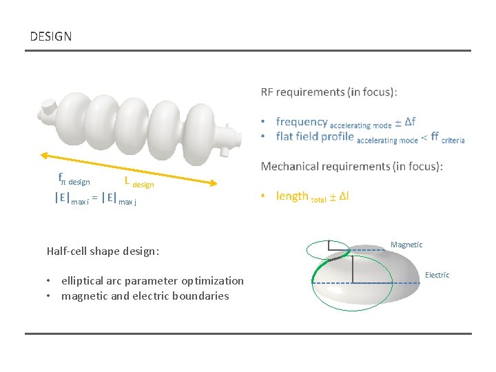
DESIGN fπ design L design |E|max i = |E|max j Half-cell shape design: • elliptical arc parameter optimization • magnetic and electric boundaries Magnetic Electric
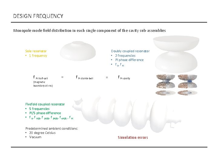
DESIGN FREQUENCY Monopole mode field distribution in each single component of the cavity sub-assemblies Sole resonator • 1 frequency f Pi half-cell Doubly coupled resonator • 2 frequencies • Pi phase difference • f 0, f Pi = f Pi dumb-bell = f Pi cavity (magnetic boundary at iris) Fivefold coupled resonator • 5 frequencies • Pi/5 phase difference • f 0, f Pi/5, f 2 Pi/5, f 3 Pi/5, f 4 Pi/5 , f Pi Predetermined ambient conditions: • 20 degree Celsius • Vacuum Simulation errors
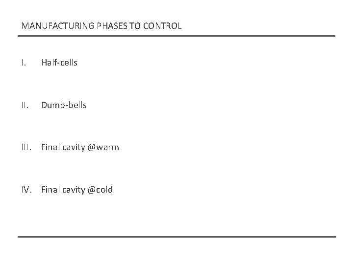
MANUFACTURING PHASES TO CONTROL I. Half-cells II. Dumb-bells III. Final cavity @warm IV. Final cavity @cold
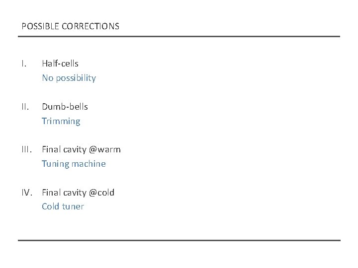
POSSIBLE CORRECTIONS I. Half-cells No possibility II. Dumb-bells Trimming III. Final cavity @warm Tuning machine IV. Final cavity @cold Cold tuner
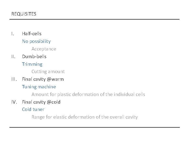
REQUISITES I. Half-cells No possibility Acceptance II. Dumb-bells Trimming Cutting amount III. Final cavity @warm Tuning machine Amount for plastic deformation of the individual cells IV. Final cavity @cold Cold tuner Range for elastic deformation of the overall cavity
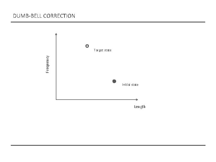
DUMB-BELL CORRECTION Frequency Target state Initial state Length
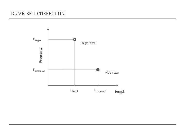
DUMB-BELL CORRECTION f target Frequency Target state f measured Initial state L target L measured Length
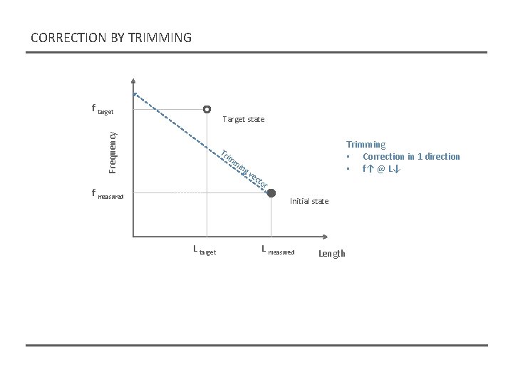
CORRECTION BY TRIMMING f target Frequency Target state Tr im mi f measured ng ve Trimming • Correction in 1 direction • f↑ @ L↓ cto r Initial state L target L measured Length
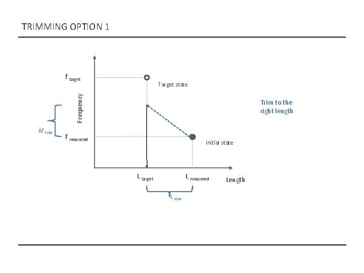
TRIMMING OPTION 1 f target Frequency Target state Δf trim Trim to the right length f measured Initial state L target L measured L trim Length
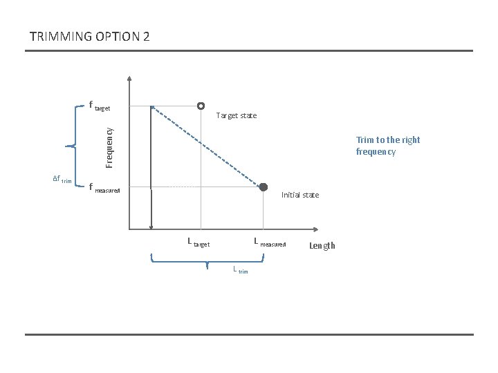
TRIMMING OPTION 2 f target Frequency Target state Δf trim Trim to the right frequency f measured Initial state L target L measured L trim Length
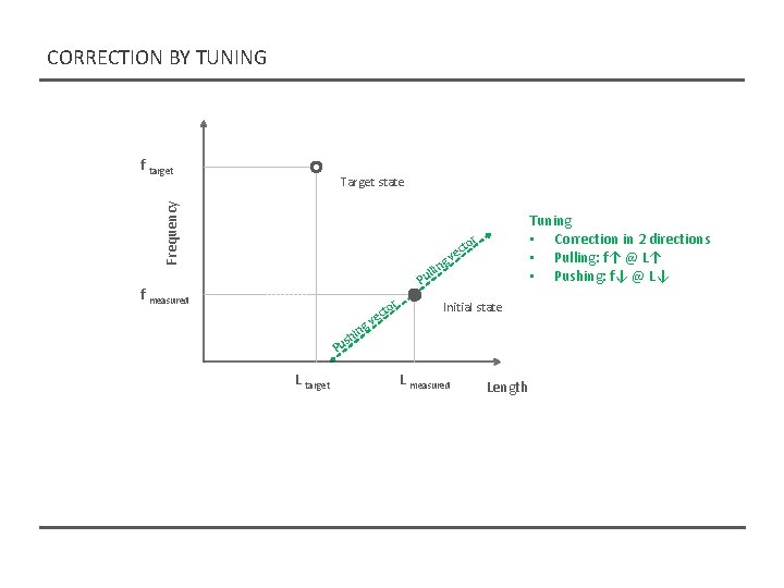
CORRECTION BY TUNING f target Frequency Target state Tuning • Correction in 2 directions • Pulling: f↑ @ L↑ • Pushing: f↓ @ L↓ r to ec v ing l l u P f measured r L target Initial state ing h us P cto e v L measured Length
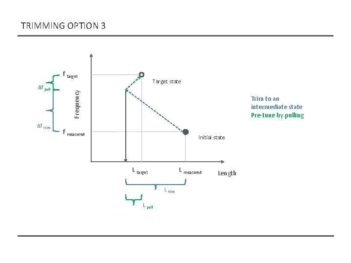
TRIMMING OPTION 3 f target Δf trim Target state Frequency Δf pull Trim to an intermediate state Pre-tune by pulling f measured Initial state L target L measured L trim L pull Length
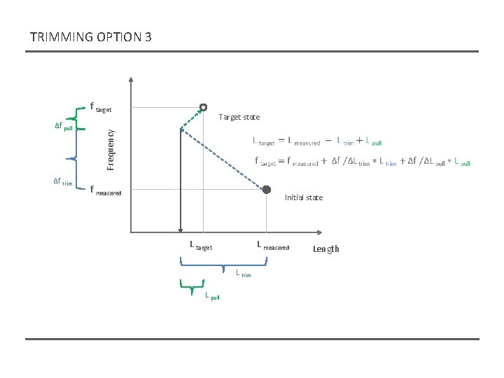
TRIMMING OPTION 3 f target Δf trim Target state Frequency Δf pull f measured Initial state L target L measured L trim L pull Length
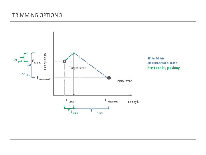
Δf push Δf trim f target Frequency TRIMMING OPTION 3 Trim to an intermediate state Pre-tune by pushing Target state f measured Initial state L target L push L measured L trim Length
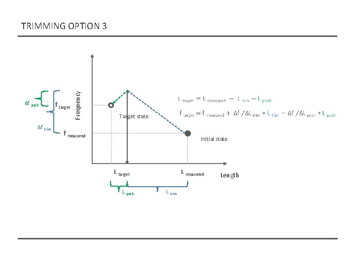
Δf push Δf trim f target Frequency TRIMMING OPTION 3 Target state f measured Initial state L target L push L measured L trim Length
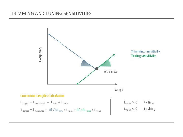
Frequency TRIMMING AND TUNING SENSITIVITIES Trimming sensitivity Tuning sensitivity Initial state Length Correction Lengths Calculation Pulling Pushing
TUNING MACHINE STATUS
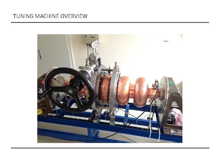
TUNING MACHINE OVERVIEW
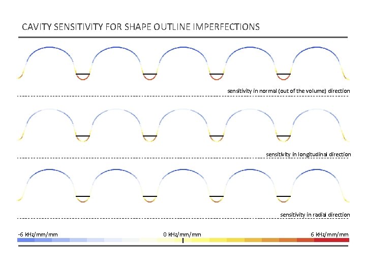
CAVITY SENSITIVITY FOR SHAPE OUTLINE IMPERFECTIONS sensitivity in normal (out of the volume) direction sensitivity in longitudinal direction sensitivity in radial direction -6 k. Hz/mm/mm 0 k. Hz/mm/mm 6 k. Hz/mm/mm
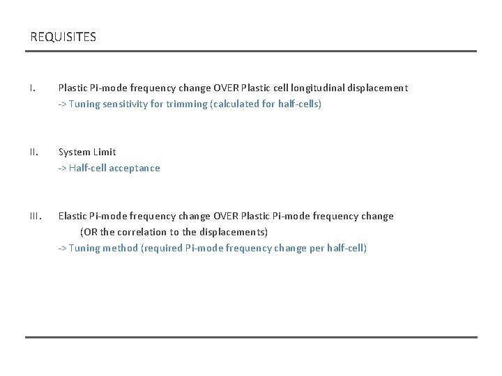
REQUISITES I. Plastic Pi-mode frequency change OVER Plastic cell longitudinal displacement -> Tuning sensitivity for trimming (calculated for half-cells) II. System Limit -> Half-cell acceptance III. Elastic Pi-mode frequency change OVER Plastic Pi-mode frequency change (OR the correlation to the displacements) -> Tuning method (required Pi-mode frequency change per half-cell)
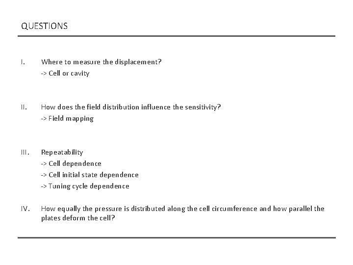
QUESTIONS I. Where to measure the displacement? -> Cell or cavity II. How does the field distribution influence the sensitivity? -> Field mapping III. Repeatability -> Cell dependence -> Cell initial state dependence -> Tuning cycle dependence IV. How equally the pressure is distributed along the cell circumference and how parallel the plates deform the cell?
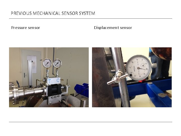
PREVIOUS MECHANICAL SENSOR SYSTEM Pressure sensor Displacement sensor
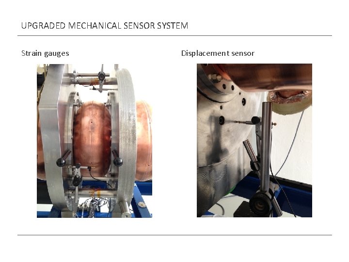
UPGRADED MECHANICAL SENSOR SYSTEM Strain gauges Displacement sensor
MECHANICAL TESTS
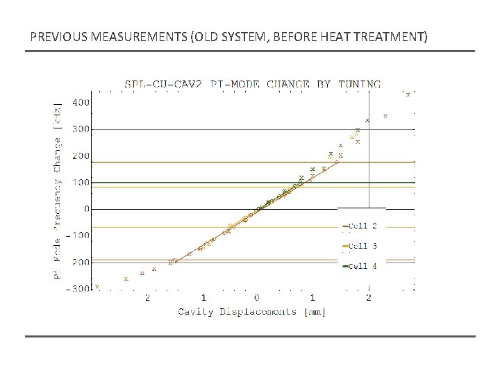
PREVIOUS MEASUREMENTS (OLD SYSTEM, BEFORE HEAT TREATMENT)
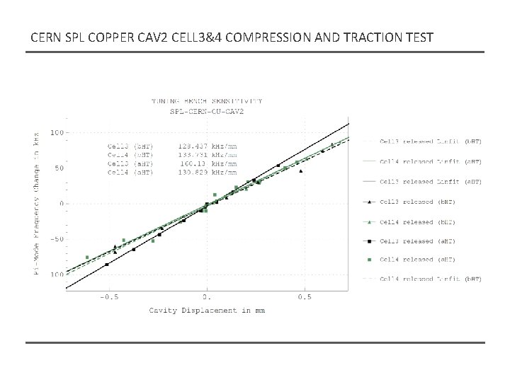
CERN SPL COPPER CAV 2 CELL 3&4 COMPRESSION AND TRACTION TEST
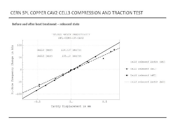
CERN SPL COPPER CAV 2 CELL 3 COMPRESSION AND TRACTION TEST Before and after heat treatment – released state
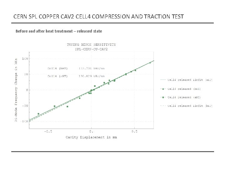
CERN SPL COPPER CAV 2 CELL 4 COMPRESSION AND TRACTION TEST Before and after heat treatment – released state
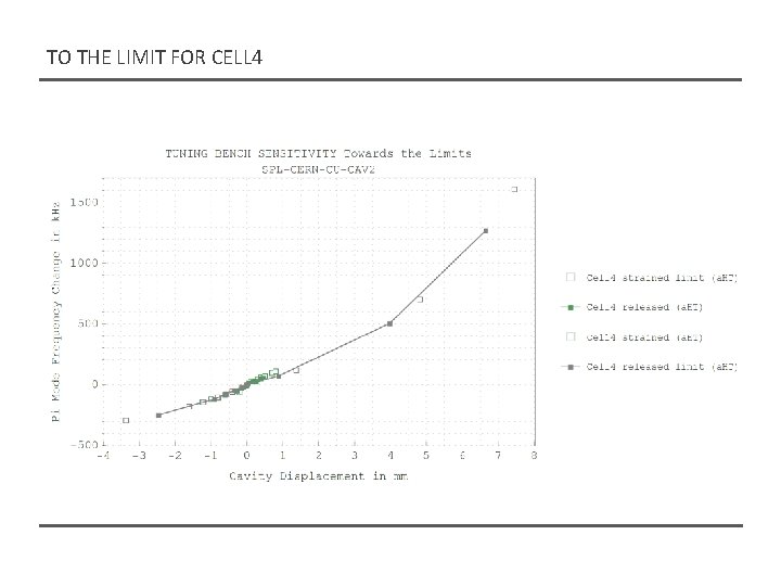
TO THE LIMIT FOR CELL 4
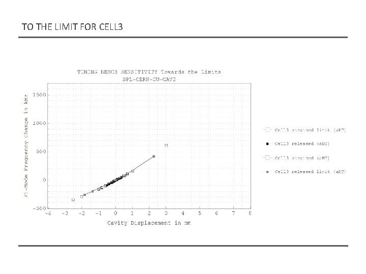
TO THE LIMIT FOR CELL 3
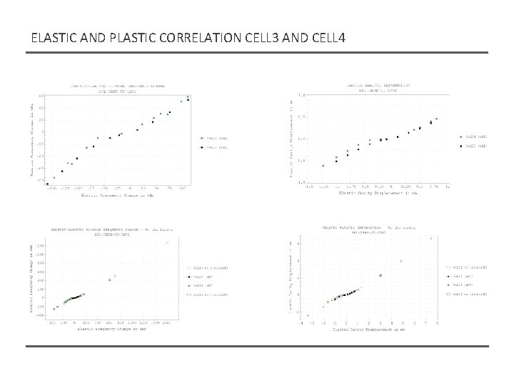
ELASTIC AND PLASTIC CORRELATION CELL 3 AND CELL 4
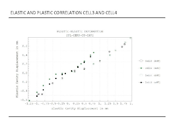
ELASTIC AND PLASTIC CORRELATION CELL 3 AND CELL 4
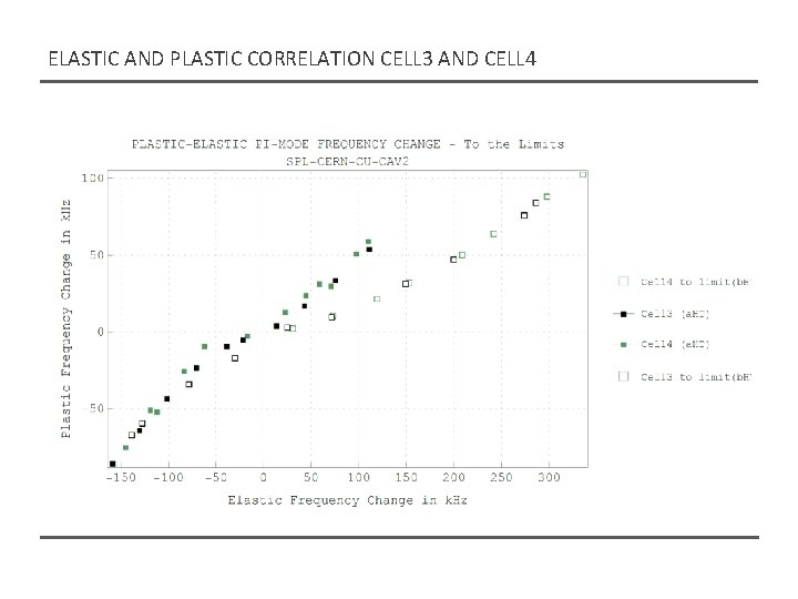
ELASTIC AND PLASTIC CORRELATION CELL 3 AND CELL 4
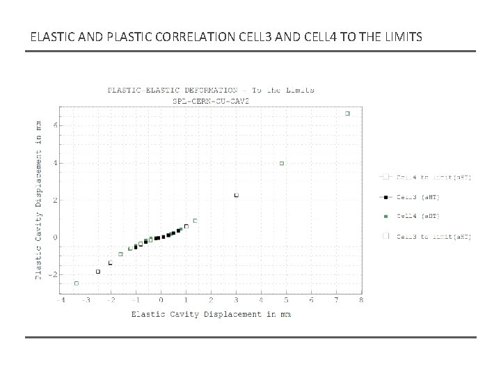
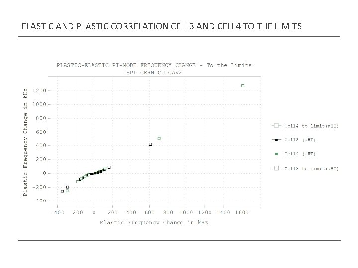
ELASTIC AND PLASTIC CORRELATION CELL 3 AND CELL 4 TO THE LIMITS
ELASTIC AND PLASTIC CORRELATION CELL 3 AND CELL 4 TO THE LIMITS
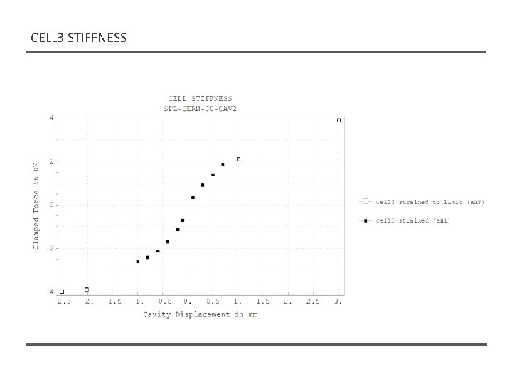
CELL 3 STIFFNESS