Programme M Sc Chemistry Session 2019 2021 SemesterII


 : Each oxygen atom inside the")


 except")


 8 x")
 Crystal Structures All crystal structures may be described in terms of the unit")


 pack to best fill space? ?")


2+ e 2 = 3 e 2")


 of prominent crystal faces")


 surface Assignment Intercepts :")
 surface Assignment Intercepts :")


- Slides: 82
Programme : M. Sc. Chemistry, Session: 2019 -2021, Semester-II Course Title: Solid State and Structural Chemistry Course Code: MSCHE 2001 E 04 Introduction to Solid State Dr. Amiya Priyam Associate Professor Department of Chemistry Central University of South Bihar Gaya-824236
Solid state Characteristics: Ø Definite volume and shape. Ø Regular order of arrangement of particles. Ø Strong intermolecular forces. Ø Low kinetic energy.
Classification of Solids • Solids can be classified as crystalline or amorphous. (on the basis of arrangement of constituent atoms/moleccules) A crystalline solid is composed of one or more crystals; each crystal has a welldefined, ordered structure in three dimensions. They have sharp melting point Examples include sodium chloride and sucrose. An amorphous solid has a disordered structure. It lacks the well-defined arrangement of basic units found in a crystal. They melt over a wide range of temperature. Glass is an example of amorphous solid.
Classification of Solids
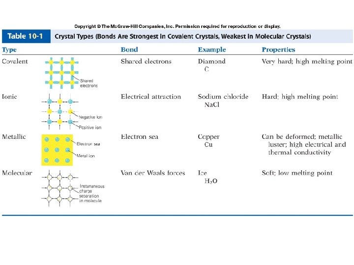
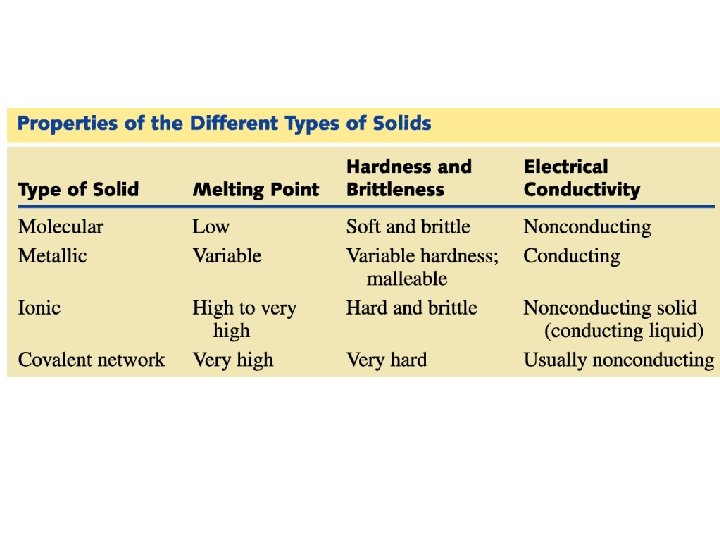
Classification of Solids • Solids can be classified into four types (based on nature of bonding) Molecular (Van der Waals forces) Covalent (Covalent bond) Metallic (Metallic bond) Ionic (Ionic bond)
Molecular solids A molecular solid is a solid that consists of atoms or molecules held together by weak intermolecular forces. Many solids are of this type. Soft, low melting point, volatile, electrical insulators, poor thermal fusion. Examples: Solid neon (melting point of -248 o. C), Solid CO 2 (dry ice), Solid H 2 O (ice) Iodine, Sugar ØIn non-polar molecules, the inter- molecular forces are only weak van der Waals forces. ØPolar molecules have dipoles and so have slightly stronger attractions between them meaning that the melting point of a polar molecular solid is a little higher because more energy is needed to overcome the slightly stronger forces.
Molecular solids Examples forces of attraction between particles weaken liquid iodine (by increasing the temp. ) solid iodine (at room temp. ) Gaseous iodine forces of attraction between particles broken (by further raising the temp. )
Molecular solids Ice ( solid form of water) : Each oxygen atom inside the ice hexagonal lattice is surrounded by four other oxygen atoms in a tetrahedral arrangement. The distance between oxygens is approximately 2. 75 Angstroms. The hydrogen atoms in ice arranged following the following manner: 1) two protons are close (about 0. 98 A) to each oxygen atom, much like in a free water molecule; 2) each H 20 molecule is oriented so that the two protons point toward two adjacent oxygen atoms; 3) there is only one proton between two adjacent oxygen atoms; 4) under ordinary conditions any of the large number of possible configurations is equally probable.
Molecular solids • The covalent bonds inside the molecules are very strong. The molecules don't break apart easily. However the forces attracting neighbouring molecules to each other are very weak. It is therefore very easy to separate molecules from one another: e. g. ammonia • When a molecular solid melts, it is the forces between the molecules which are broken. Very little energy is needed to make this happen, so molecular solids have low melting points
Metallic Solids A metallic solid is a solid that consists of positive metal ions held together by a surrounding “sea of electrons “(metallic bonding). In this kind of bonding, positively charged metal ions form the lattice which is submerged in the “sea of electrons” Or, the metal ions occupy fixed position in the lattice structure and they are surrounded by delocalized electrons. Therefore, the intermolecular forces in metals must be rather strong. Very soft to very hard, low to high melting point, good conductors of electricity and heat. Metallic lustre, malleable and ductile, moderate heats of fusion Examples include iron, copper, and silver.
• Metallic Solids The lattice is held by strong electrostatic attraction between the delocalized electrons and metallic cations known as metallic bonds The strength of metallic bond varies and so consequently the melting and boiling points of different metals varies. • Malleable and ductile due to non-directional metallic bonds • Good conductors of heat and electricity due to high density and mobile electrons • High melting and boiling points due to strong metallic bonds Illustration of the malleability and ductility of a metal
Ionic Solids An ionic solid is a solid that consists of cations and anions held together by electrostatic attraction of opposite charges (ionic bond). • Brittle, high melting point, good conductors in the aqueous solution or fused state, high heats of fusion. Salts like Na. Cl, KNO 3, Li. F, Ba. SO 4 etc.
Properties: Ionic Solids • Do not conduct electricity (no free ions or electrons) except when molten or aqueous (as ions are free to move) • High melting point and boiling point because of very strong electrostatic attractions between cations and anions • Soluble in polar solvents
Ionic Solids Properties: 1. High melting and boiling points 2. Hard but brittle The giant ionic structure fractures when a stress is applied
Covalent Solids A covalent network solid is a solid that consists of atoms held together in large networks or chains by covalent bonds. Very hard, high melting point, poor conductors of heat and electricity high heats of fusion. Examples include carbon, in its forms as diamond or graphite, asbestos, and silicon carbide.
Covalent Solids Three types: 1. 2. 3. Linear chains 2 -D layers 3 -D covalent network
Covalent Solids Linear chains are infinitely long linear chains held together by van der Waals Properties: • Low MP, but longer chains have higher MP than shorter ones • Do not conduct electricity • Soft and flexible • Eg. Polythene, rubber, plastics
Covalent Solids 2 -D Layers held together by weak van der Waals forces. Graphite is made of layers of covalently bonded C atoms. The layers are held together by weak van der Waals forces and have delocalised electrons between them. *this is very unusual and graphite is the only non-metal to conduct electricity
Covalent Solids 3 -D covalent network solids are made of atoms held together by strong covalent bonds. Diamond and silica (silicon dioxide) are two examples of covalent network solids. Diamond is the strongest substance known to man. Covalent network solids have • High MP (strong covalent bonds hold atoms in place) • Do not conduct electricity (all electrons held in covalent bonds) • Very hard/strong • Insoluble in any solvent Diamond
Crystal Lattices • A crystal lattice is the geometric arrangement of lattice points in a crystal. A unit cell is the smallest boxlike unit from which you can construct a crystal by stacking the units in three dimensions (see Figure 11. 29). There are seven basic shapes possible for unit cells, which give rise to seven crystal systems used to classify crystals (see Figure 11. 31 and Table 11. 7). Copyright © by Houghton Mifflin Company. All rights reserved.
Figure 11. 30: Crystal structure and crystal lattice of copper. Copyright © by Houghton Mifflin Company. All rights reserved.
Figure 11. 31: Unit-cell shapes of the different crystal systems. Copyright © by Houghton Mifflin Company. All rights reserved.
Copyright © by Houghton Mifflin Company. All rights reserved.
Cubic Unit Cells • A simple cubic unit cell is a cubic cell in which the lattice points are situated only at the corners. A body-centered cubic unit cell is one in which there is a lattice point in the center of the cell as well as at the corners. A face-centered cubic unit cell is one in which there are lattice points at the center of each face of the cell as well as at the corners (see Figures 11. 30, 11. 32, and 11. 33). Copyright © by Houghton Mifflin Company. All rights reserved.
Figure 11. 32: Cubic unit cells. Copyright © by Houghton Mifflin Company. All rights reserved.
Cubic unit cell CN = 6 Axial length a=b=c Axial angle CN = 8 CN = 12
Figure 11. 33: Space-filling representation of cubic unit cells. Copyright © by Houghton Mifflin Company. All rights reserved.
The cubic crystal lattices are of three types 1. simple cubic (sc) 8 x 1/8 atom per corner = one atom per cell 2. body-centered cubic (bcc) 8 x 1/8 atoms per corner + one atom in center = 2 atoms / cell 3. face-centered cubic (fcc) 8 x 1/8 atom / corner + ½ atom per side x 6 sides = 4 atoms per cell
(Inorganic) Crystal Structures All crystal structures may be described in terms of the unit cell and atomic coordinates of the contents Many inorganic structures may be described as arrays of space filling polyhedra - tetrahedra, octahedra, etc. Many structures - ionic, metallic, covalent may be described as close packed structures
Packing Can pack with irregular shapes
Close packed structures - metals Most efficient way of packing equal sized spheres. In 2 D, have close packed layers Coordination number (CN) = 6. This is the maximum possible for 2 D packing. Can stack close packed (c. p. ) to give 3 D structures.
Closest Packing of Spheres How do spheres (atoms) pack to best fill space? ? The concept of closest packing is important for understanding many solid structures
Closest Packing of Circles r Arrange circles in regular pattern with all edges touching What percentage of space do circles packed in this fashion fill? Area of rectangle = 6 r x 8 r = 48 r 2 Area filled by circles = 12 x (πr 2) = 12πr 2 Percentage of space filled by circles = 37. 7/48 = 78. 5%
Closest Packing of Circles r Arrange circles in regular pattern with all edges touching. Shift by r and nudge up to maximize packing What percentage of space does this fill? base x height 4 r x = Area of triangle = 2 2 r = r 2 Area filled by circles = 3 x (1/6πr 2) + 3 x (1/2πr 2) = 2πr 2 Percentage of space filled by circles = 6. 28/6. 93 = 91%
Closest Packing of Spheres Imagine you are looking down at the tops of a group of spheres a b There are two choices of hollows to place the next layer of spheres, a and b Note that once we have chosen to put the second layer sphere into site a, we can no longer put a sphere into site b. a b a b
Closest Packing of Spheres Imagine you are looking down at the tops of two layers of spheres y x Note, we have two type of sites for the third layer, x and y. Site x is located above layer one sphere Site y is located above layer one hole Note, once again we can only fill x or y sites, not both, with new spheres y x
Closest Packing of Spheres x y Filling the x sites Filling the y sites ABABAB…. Packing ABCABCABC…. Packing Hexagonal close packing (HCP) Cubic close packing (CCP)
Hexagonal Close Packed Lattice
Cubic Close Packed Lattice
Coordination in HCP and CCP Each atom is surrounded by six atoms in the same plane There an additional three atoms in the planes above and below Every atom has a total of twelve nearest neighbors
Percent of Volume Filled by Close-Packed Spheres Calculate for FCC cell: Let radius of spheres = r • cell diagonal = 4 r • cell edge = r Volume of spheres = 4 x (4/3πr 3) Volume of cube = 4 atoms in cell volume of spheres = 16. 76/22. 63 = 0. 74 volume of cube Percent volume occupied = 74%
Density can be used to find atomic radius if type of crystal is known. For fcc 2 x cell edge e 2 + e 2 = l 2 = 2 e 2 l = 2 e l = four atom radii Volume of cell = e 3
d = m /V • density of metal = mass of cell/ Volume • Mass of cell is mass of four atoms of metal • Mass of cell = atom mass / mol x 1 mol/ 6. 022 x 1023 atoms x 4 atom/cell Example: the density of Al is 2. 699 g/cm 3 the Volume of a unit cell is 6. 640 x 10 -23 cm 3 and the atomic radius is then 143 pm l = 2 e l = four atom radii Volume of cell = e 3
For Iron which has a bcc unit cell the calculation is a little different The Density of Iron is 7. 8470 g/cm 3 2 e D 2 = ( 2 e)2+ e 2 = 3 e 2 D = 3 e
D e D 2 = ( 2 e)2+ e 2 = 3 e 2 D = 3 e 2 e There are two atoms per unit cell Volume of cell = e 3 e = D/ 3 V = e 3= m/density D=4 xr m = 2 x 55. 85 g/6. 022 x 1023 atoms atom mass of Fe = 55. 85 g/mol e 3 = 1. 85 x 10 -22/ 7. 8470 g/cm 3 e = 2. 87 x 10 -8 cm This gives cell edge of 287 pm and r = 124 pm
Finding the Lattice Type To find out if a metal is SC, BCC or FCC, use the known radius and density of an atom to calc. no. of atoms per unit cell. PROBLEM Al has density = 2. 699 g/cm 3 and Al radius = 143 pm. Verify that Al is FCC. SOLUTION 1. Calc. unit cell volume
Finding the Lattice Type PROBLEM Al has density = 2. 699 g/cm 3 and Al radius = 143 pm. Verify that Al is FCC. SOLUTION To find out if a metal is SC, BCC or FCC, use the known radius and density of an atom to calc. no. of atoms per unit cell. 1. Calc. unit cell volume V = (cell edge)3 Edge distance comes from face diagonal. Diagonal distance = Ö 2 • edge
Finding the Lattice Type PROBLEM Al has density = 2. 699 g/cm 3 and Al radius = 143 pm. Verify that Al is FCC. SOLUTION Here diagonal = 4 • radius of Al = 572 pm Therefore, edge = 572 pm / Ö 2 = 404 pm In centimeters, edge = 4. 04 x 10 -8 cm So, V of unit cell = (4. 04 x 10 -8 cm)3 V = 6. 62 x 10 -23 cm 3
Finding the Lattice Type PROBLEM Al has density = 2. 699 g/cm 3 and Al radius = 143 pm. Verify that Al is FCC. SOLUTION 2. Use V and density to calc. mass of unit cell from DENS = MASS / VOL Mass = density • volume = (6. 62 x 10 -23 cm 3)(2. 699 g/cm 3) = 1. 79 x 10 -22 g/unit cell
Finding the Lattice Type PROBLEM Al has density = 2. 699 g/cm 3 and Al radius = 143 pm. Verify that Al is FCC. SOLUTION 3. Calculate number of Al per unit cell from mass of unit cell.
Finding the Lattice Type PROBLEM Al has density = 2. 699 g/cm 3 and Al radius = 143 pm. Verify that Al is FCC. SOLUTION 3. Calculate number of Al per unit cell from mass of unit cell. 1 atom = 4. 480 x 10 -23 g, so
Finding the Lattice Type PROBLEM Al has density = 2. 699 g/cm 3 and Al radius = 143 pm. Verify that Al is FCC. SOLUTION 3. Calculate number of Al per unit cell from mass of unit cell. 1 atom = 4. 480 x 10 -23 g, so
Number of Atoms per Unit Cell How can there be 4 atoms in a unit cell? 1. Each corner Al is 1/8 inside the unit cell. 8 corners (1/8 Al per corner) = 1 net Al 2. Each face Al is 1/2 inside the cell 6 faces (1/2 per face) = 3 net Al’s
Number of Atoms per Unit Cell Type FCC SC BCC Net Number Atoms 4 1 2
Simple Ionic Compounds Lattices of many simple ionic solids are built by taking a SC or FCC lattice of ions of one type and placing ions of opposite charge in the holes in the lattice. EXAMPLE: Cs. Cl has a SC lattice of Cs+ ions with Cl- in the center.
Simple Ionic Compounds Cs. Cl has a SC lattice of Cs+ ions with Cl- in the center. 1 unit cell has 1 Cl- ion plus (8 corners)(1/8 Cs+ per corner) = 1 net Cs+ ion.
Simple Ionic Compounds Salts with formula MX can have SC structure — but not salts with formula MX 2 or M 2 X
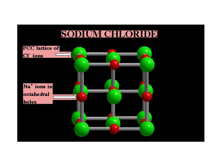
Simple Ionic Compounds Many common salts have FCC arrangements of anions with cations in OCTAHEDRAL HOLES — e. g. , salts such as CA = Na. Cl • FCC lattice of anions ----> 4 A-/unit cell • C+ in octahedral holes ---> 1 C+ at center + [12 edges • 1/4 C+ per edge] = 4 C+ per unit cell
Construction of Na. Cl We begin with a cube of Cl- ions. Add more Cl- ions in the cube faces, and then add Na+ ion in the octahedral holes.
The Sodium Chloride Lattice Na+ ions are in OCTAHEDRAL holes in a face-centered cubic lattice of Cl- ions.
Comparing Na. Cl and Cs. Cl • Even though their formulas have one cation and one anion, the lattices of Cs. Cl and Na. Cl are different. • The different lattices arise from the fact that a Cs+ ion is much larger than a Na+ ion.
Common Ionic Solids Titanium dioxide, Ti. O 2 There are 2 net Ti 4+ ions and 4 net O 2 ions per unit cell.
Common Ionic Solids • Zinc sulfide, Zn. S • The S 2 - ions are in TETRAHEDRAL holes in the Zn 2+ FCC lattice. • This gives 4 net Zn 2+ ions and 4 net S 2 ions.
Common Ionic Solids • Fluorite or Ca. F 2 • FCC lattice of Ca 2+ ions • This gives 4 net Ca 2+ ions. • F- ions in all 8 tetrahedral holes. • This gives 8 net F- ions.
Lattice Planes & Miller Indices Lattice plane is any plane containing at least three noncollinear lattice points Ø A 3 -D lattice consist of symmetrically organized atoms intersecting three sets of parallel planes. Ø These parallel planes are "crystal planes" and are used to determine the shape and structure of the unit cell and crystal lattice. Ø The planes intersect with each other and make 3 D shapes that have six faces. Ø These crystal planes define the crystal structure by making axes visible and are the means by which we can calculate the Miller Indices.
Lattice Planes & Miller Indices Lattice plane is any plane containing at least three noncollinear lattice points Any crystallographic plane can be specified by three integers (h, k, l) – the Miller indices. The indices of any given plane can be worked out by considering the intersection of the plane with the crystallographic unit cell vectors a, b, c. If x, y, z are the fractional coordinates of the intersections of the plane with a, b, c, Miller indices are the smallest integers in the same ratio as (1/x, 1/y, 1/z).
Crystal Axis: generally taken as parallel to the edges (intersections) of prominent crystal faces b a c
Lattice Planes & Miller Indices The orientation of a surface or a crystal plane may be defined by considering how any plane intersects the main crystallographic axes of the solid. The application of a set of rules leads to the assignment of the Miller Indices, (hkl). These are a set of numbers that may be used to identify the plane or surface. To calculate Miller Indices, follow these steps: 1. Determine the intercepts of the face along the crystallographic axes, in terms of unit cell dimensions, then: ØTake the reciprocals ØClear fractions ØReduce to lowest terms For example, if the x-, y-, and z- intercepts are 3, 1, and 6, the Miller indices are calculated as follows: 1. Take reciprocals: 1/3, 1/1, 1/6 2. Clear fractions {multiply by 6}: 2, 6, 1 3. Reduce to lowest terms (already there)
Lattice Planes & Miller Indices The following treatment of the procedure used to assign the Miller Indices is a simplified one. only a cubic crystal system (one having a cubic unit cell with dimensions a x a ) will be considered
Lattice Planes & Miller Indices Step 1 : Identify the intercepts on the x- , y- and z- axes. §In this case the intercept on the xaxis is at x = a ( at the point (a, 0, 0) §The surface is parallel to the y- and z -axes. Strictly, therefore, there is no intercept on these two axes. But, we shall consider the intercept to be at infinity ( ∞ ) for the special case where the plane is parallel to an axis. The intercepts on the x- , y- and zaxes are thus § Intercepts : a , ∞
Lattice Planes & Miller Indices Step 2 : Specify the intercepts in fractional co-ordinates § Co-ordinates are converted to fractional co-ordinates by dividing by the respective cell-dimension. §For example, a point (x, y, z) in a unit cell of dimensions a x b x c has fractional co-ordinates of ( x/a, y/b , z/c ). §In the case of a cubic unit cell each co-ordinate will simply be divided by the cubic cell constant , a. §Fractional Intercepts : a/a , ∞/a i. e. 1 , ∞
Lattice Planes & Miller Indices Step 2 : Take the reciprocals of the fractional intercepts § This final manipulation generates the Miller Indices which (by convention) should then be specified without being separated by any commas or other symbols. § The Miller Indices are also enclosed within standard brackets (…. ) when one is specifying a unique surface such as that being considered here. § The reciprocals of 1 and ∞ are 1 and 0 respectively, thus yielding Miller Indices : (100) (hkl) So the surface/plane illustrated is the (100) plane of the cubic crystal
Lattice Planes & Miller Indices Other examples v. The (110) surface Assignment Intercepts : a , ∞ Fractional intercepts : 1 , ∞ Miller Indices : (110) (hkl)
Lattice Planes & Miller Indices Other examples v. The (111) surface Assignment Intercepts : a , a Fractional intercepts : 1 , 1 Miller Indices : (111) (hkl)
Interplanar distance d
Lattice Planes & Miller Indices Ø By the set of crystallographic planes hkl, we mean a set of parallel equidistant planes, one of which passes through the origin, and the next nearest makes intercepts a/h, b/k, and c/l on the three crystallographic axes. Ø The integers hkl are usually called the Miller indices
Lattice Planes & Miller Indices Ø For plane A, a/2, b/2, and 1 c 2, 2, 1 plane is (221) Ø For plane B, 1 a, 1 b, and 2 c, 1, 1, 1/2 2, 2, 1 plane is (221) Ø For plane C, 3 a/2, 3 b/2, and 3 c 2/3, 1/3 2, 2, 1 plane is (221) Ø For plane D, 2 a, 2 b, and 4 c, 1/2, 1/4 2, 2, 1 plane is (221)
Ingterplanar Distance & Miller Indices Ø Since for orthogonal axes:
Interplanar distance and Miller Indices