Photovoltaic Power Converter Students Thomas Carley Luke Ketcham


 System")


 and carrier (red) waveforms Switching signal")


- Slides: 52
Photovoltaic Power Converter Students: Thomas Carley Luke Ketcham Brendan Zimmer Greg Landgren Advisors: Dr. Woonki Na Dr. Brian Huggins Dr. Yufeng Lu Bradley University Department Of Electrical Engineering 11/30/11
Presentation Outline Summary and Overall System Block Diagram DC Subsystem Maximum Power Point Tracking Boost Converter Testing AC Subsystem Schedule Component List
Project Summary Supplies DC and AC Power Photovoltaic Array Boost Converter to step up PV voltage Maximum Power Point Tracking DC-AC converter for 120 Vrms LC filter
System Block Diagram
DC Subsystem Boost Converter Maximum Power Point Tracking (MPPT) System
Simulation Results
Boost Converter Full Bridge
DC Subsystem Requirements The boost converter shall accept a voltage from the photovoltaic cells. The input voltage shall be 48 Volts. The average output shall be 200 Volts +/- 25 Volts. The voltage ripple shall be less than 3 Volts The boost converter shall perform maximum power point tracking. The PWM of the boost converter shall be regulated based on current and voltage from the PV array. The efficiency of the MPPT system shall be above 85%.
DC Subsystem Key Components MOSFET Vds = 250 V Id = 110 A Pdiss = 694 W Heatsink Inductor 1 m. H 25 A 500 u. H 35 A Gate Driver MOSFET or IGBT 2. 5 A 500 V Solar Panel x 4 50 W 12 V
DC Subsystem Components Current Sensor 30 A 63 -69 m. V/A Sensing Op amp Used with voltage divider DSP Board TMS 320 F 2812
MPPT “Perturb and Observe” method Change Boost Converter duty cycle based on change in PV power Changing duty cycle changes the current drawn from the PV Anytime the system is not at the maximum power point, it is not at it’s most efficient point
MPPT Flowchart
Boost Without MPPT
Boost With MPPT
MPPT Circuit
Output Power Without MPPT
Output Power With MPPT
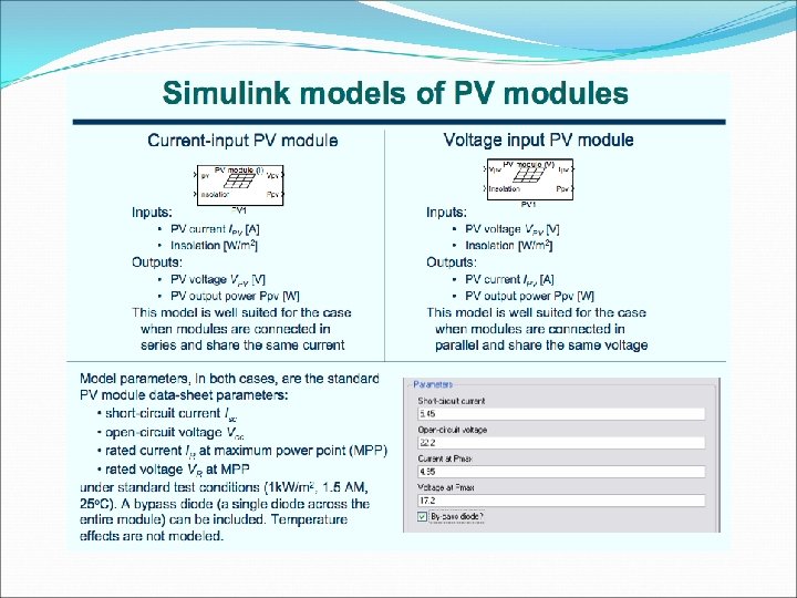
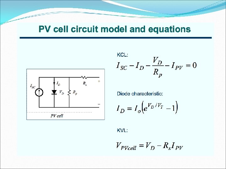
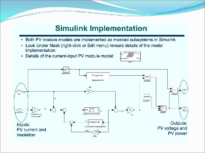
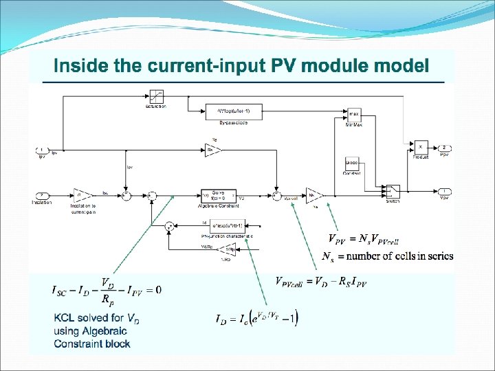
PV Models in Simulink Made models of PVs using resources from the University of Colorado at Boulder Insolation – a measure of solar energy on an area over a given amount of time. Usually in units of W/m^2 Solar Insolation Peoria, IL Jan k. Wh/(m^2 day) W/m^2 Feb March April May June July Aug Sep Oct Nov Dec 3. 271 4. 109 4. 642 4. 921 5. 239 5. 740 5. 880 5. 727 5. 639 4. 562 2. 957 2. 721 136. 292 171. 208 193. 417 205. 042 218. 292 239. 167 245. 000 238. 625 234. 958 190. 083 123. 208 113. 375
I P V V
Insolation = 200, 400, 600, 800, 1000 W/m 2 P I V V
I V P V
Boost Converter Lab Testing Built boost converter from components Dr. Na provided.
Boost Converter Lab Testing 0 to 3. 3 V signal from DSP board controlling the MOSFET At a switching frequency of 10 k. Hz with a 50% duty cycle the 5 V input voltage was boosted to about 10 V. Increasing duty cycle, increased Vout Decreasing duty cycle, decreased Vout After testing this setup we will be able to build our Boost converter circuit quickly.
DSP Board Programming Spectrum Digital e. Zdsp F 2812 Texas Instruments Code Composer Matlab/Simulink
Simulink A/D Interfacing
Simulink PWM Generation
Manual PWM Duty Ratio Control
PWM Generation Experimental Results 80% Duty Ratio 30% Duty Ratio
AC Subsystem Inverter Output filter
AC Subsystem - Inverter topology Inverter operation Simulations
AC Subsystem Inverter Topology Inverter single phase H-bridge
AC Subsystem Inverter Operation - Bipolar A reference sinusoidal waveform is compared to a triangular carrier waveform When the reference voltage is equal to the carrier voltage a transition in the switching signal occurs
AC Subsystem Inverter Operation - Bipolar Simulation schematic
AC Subsystem Inverter Operation - Bipolar Reference (blue) and carrier (red) waveforms Switching signal
AC Subsystem Inverter Operation - Bipolar Inverter output. Switches from +Vd to -Vd
AC Subsystem Inverter Operation - Bipolar Switching signal is inverted and fed to other pair of switches Switch pairs are switched simultaneously Only one reference signal needed, but performance is poor
AC Subsystem Inverter Operation - Unipolar Two reference sinusoids are compared to a triangular waveform Switch pairs not switched simultaneously
AC Subsystem Inverter Operation - Unipolar Simulation schematic
AC Subsystem Inverter Operation - Unipolar References and carrier waves Switching signal 1 Switching signal 2 Output Image source: Tian
Inverter Operation - Comparison Bipolar harmonic output Unipolar harmonic output
AC Subsystem - Output Filter Inverter output includes switching harmonics Filter smoothes output
AC Subsystem Requirements The AC side of the system shall invert the output of the boost converter. The output of the inverter shall be 120 Volts RMS. The output shall be 60 Hz +/- 0. 1 Hz. The inverter output shall be filtered by a LC filter. The filter shall remove high switching frequency harmonics. Total harmonic distortion of the output shall be less than 15%.
AC Subsystem Key Components Inverter switches Gate drives Power supplies
Commercial Grid Tie Inverters Company SMA Solar Technology Product Sunny Boy 700 -US AC Power 460 W, 120 Vac AC Voltage 106 - 132 Vac Output Frequency 59. 3 - 60. 5 Hz Harmonics > 3% Max. efficiency 92. 4% Power Factor Unity Xantrex GT 2. 8 2700 W, 208 Vac / 2800 W, 240 Vac 183 - 229 Vac / 211 - 264 Vac 59. 3 - 60. 5 Hz > 3% 94. 6% > 0. 95 %
Schedule
Component List
References “PV Module Simulink Models. ” ECEN 2060. University of Colorado Boulder. Rozenblat, Lazar. "A Grid Tie Inverter for Solar Systems. " Grid Tie Inverter Schematic and Principles of Operation. 6 Oct. 2011. <http: //solar. smps. us/grid-tie-inverterschematic. html>. Tafticht, T. , K. Agbossou, M. Doumbia, and A. Cheriti. "An Improved Maximum Power Point Tracking Method for Photovoltaic Systems. " Renewable Energy 33. 7 (2008): 1508516. Tian, Yi. ANALYSIS, SIMULATION AND DSP BASED IMPLEMENTATION OF ASYMMETRIC THREE-LEVEL SINGLE-PHASE INVERTER IN SOLAR POWER SYSTEM. Thesis. Florida State University, 2007. Zhou, Lining. EVALUATION AND DSP BASED IMPLEMENTATION OF PWM APPROACHES FOR SINGLE-PHASE DC-AC CONVERTERS. Thesis. Florida State University, 2005.
Questions?