PATIENTMOTION ANALYSIS IN PERFUSION WEIGHTED MRI Rohit Gautam


- Slides: 52

PATIENT-MOTION ANALYSIS IN PERFUSION WEIGHTED MRI Rohit Gautam IIIT Hyderabad 200702035 CVIT, IIIT Hyderabad Guide Dr. Jayanthi Sivaswamy

What is Perfusion MRI ? • In the context of MRI, observation of blood flow through an organ is referred to as perfusion. • A bolus of an exogenous paramagnetic contrast agent injected into patient’s blood stream is tracked over time. • Acquired data is 3 D time-series. m olu IIIT Hyderabad V 1 Before Bolus wash-in nwin Bolus in transit Time-points nwout After Bolus wash-out N e

Perfusion MRI in stroke analysis • Stroke: Rapid loss in brain function due to disturbance in blood supply. 1. Interruption to blood supply (Ischemic) 2. Blood vessel rupture (Haemorrhagic) • Stroke regions IIIT Hyderabad – Core (dead region) – Penumbra (salvageable) • Time-varying data (for brain) is parameterized on voxelby-voxel basis to obtain perfusion parameters. • These parameters help to profile the blood flow characteristics in different tissues and identify affected regions.

Data corruption due to patient motion • Duration of a perfusion scan lies in range 20~60 minutes. • Difficult for patient to remain still in this period. IIIT Hyderabad Volume at time t 1 Volume at time t 2 • Incorrect tracking of voxel across time-points leads to incorrect perfusion parametric maps.

Variation in perfusion parameters with motion Perfusion parameters obtained from motion corrupted data vary with degree of motion. IIIT Hyderabad Error in CBV estimation TTP: Time to Peak of contrast agent CBV: Cerebral Blood Volume Error in TTP estimation

1 Before bolus wash-in Motion nwin No variation in intensity Bolus in transit Motion nwout IIIT Hyderabad Non-uniform Variation in intensity After bolus wash-out N Motion No variation in intensity

Problem Aim • Align the volumes in a perfusion time-series corrupted due to patient motion. • Transformations found in acquired perfusion MR images: 1. Global transformation due to patient motion. 2. Local change in image intensity due to injected bolus. 3. Non-uniform nature of intensity variation due to varying concentration of bolus in brain. IIIT Hyderabad • Obstacles – Perfusion MRI is not a common practice in India. – Motion corrupted perfusion data is very difficult to acquire. • Motion is simulated.

Strategy for motion correction Observation • All volumes in the time-series are not affected by motion. Hence • Find the subset of volumes that are affected by motion. IIIT Hyderabad • Align the entire time-series by aligning this subset of volumes only.

IIIT Hyderabad Proposed three-stage system for motion correction

IIIT Hyderabad Division of perfusion time-series

Observation • A perfusion time-series cannot be treated as a single unit due to behaviour of contrast agent. Hence, • The time-series is divided into three sets based on the time-points: IIIT Hyderabad – Wash-in time-point of contrast agent – Wash-out time-point of contrast agent

Gamma-variate-function fitting • The signal intensity in perfusion MRI varies proportionally with bolus concentration. • A standard gamma-variate-function (GVF) models the perfusion curves[1]. • This GVF is fit on the mean-intensity perfusion curve µa(n) to estimate GVF-fit mean intensity curve µg(n). IIIT Hyderabad • Using µg(n), we divide the time-series into 3 sets. Wash-in Wash-out Time point [1] Simplified gamma-variate fitting of perfusion curves, ISBI 2004

IIIT Hyderabad Motion Detection

IIIT Hyderabad Motion Detection Scheme Pre-wash-in Transit Post-wash-out

Motion Detection for Set-1 and Set-3 Fn Fn+1 Extract Central Slices IIIT Hyderabad Block wise Phase Correlation Un+1 Vn+1 Process is accelerated by down-sampling of central slices.

Motion Detection for Set-2 • The injected bolus causes localized non-uniform variation in intensity in the volumes. IIIT Hyderabad • To overcome this, intensity correction is applied prior to motion detection on these volumes.

Intensity correction of volumes in set-2 • Identify the regions affected by bolus. – Segment the brain into normal and bolus affected regions using fuzzy c-means based clustering. • GVF-fitting based intensity correction of bolus affected regions: IIIT Hyderabad • Finally, the intensity corrected volume is obtained.

Intensity Correction Example Slice 1 Slice 2 Absolute Difference Reduction in absolute Ideally, these intensity should be 0 difference IIIT Hyderabad Intensity Correction Slice 1 Intensity Corrected Slice 2 Absolute Difference

IIIT Hyderabad Motion Characterization

• Aim: Categorize the volumes in none, minimal, mild or severe motion category depending on the degree of motion. • Metric used: Peak entropy IIIT Hyderabad • The peak entropy (Hpeak) of the flow fields is found as: where, H denotes the Shannon entropy of image, Hn is the net entropy.

Dataset • Perfusion MRI data was acquired from KIMS hospital. IIIT Hyderabad • Known amount of 3 D rotations were added to volumes to simulate actual patient behaviour. • Volumes were categorized into four categories – none, minimal, mild and severe. Step function used to add motion Motion Category Angle of rotation (degrees) None 0 Minimal motion [1, 5] Mild motion [6, 10] Severe motion [11, 15]

Results - Motion Flow Maps Slice 1 Slice 2 Un Vn IIIT Hyderabad Bolus present and no motion Bolus absent and minimal motion Bolus absent and mild motion

Net Entropy Profile 1 IIIT Hyderabad 33 5 8 Zero net entropy even in the presence of bolus. 40 Wash-in time-point

IIIT Hyderabad Motion Category Angle of rotation (in degrees) Peak Entropy (Hpeak) Total Entropy in U Total Entropy in V Total Entropy None 0 0. 00 Minimal 1 0. 00 Minimal 2 0. 00 Minimal 3 0. 04 0. 00 0. 04 Minimal 4 0. 08 0. 00 0. 23 Minimal 5 0. 20 0. 00 0. 76 Mild 6 0. 25 0. 00 1. 29 Mild 7 0. 40 0. 00 2. 04 Mild 8 0. 52 0. 00 2. 67 Mild 9 0. 61 0. 00 3. 25 Mild 10 0. 75 0. 08 3. 78 3. 86 Severe 11 1. 05 0. 32 4. 33 4. 65 Severe 12 1. 15 0. 48 5. 14 5. 62 Severe 13 1. 31 0. 59 5. 75 6. 34 Severe 14 1. 37 0. 85 6. 21 7. 06 Severe 15 1. 51 0. 97 6. 88 7. 85 Such a small motion cannot be detected. Peak entropy can distinguish between different motion categories. Entropy values for different motion categories for image size – 32 x 32 and block size 8 x 8

Motion Category Peak Entropy (Hpeak) None Minimal Mild Severe 0 0 < Hpeak <= 0. 25 < Hpeak <= 1 Hpeak > 1 IIIT Hyderabad Upper and lower bounds of peak entropy values for different motion categories

Effect of slice resolution and block size Slice Resolution Block Size Mean time per slice pair (sec) Total time (sec) 128 x 128 32 x 32 0. 00 + 3. 48 = 3. 48 132. 21 128 x 128 16 x 16 0. 00 + 3. 99 = 3. 99 151. 69 128 x 128 8 x 8 0. 00 + 4. 34 = 4. 34 164. 84 64 x 64 16 x 16 0. 01 + 0. 77 = 0. 78 29. 71 64 x 64 8 x 8 0. 01 + 0. 97 = 0. 98 37. 38 32 x 32 8 x 8 0. 01 + 0. 19 = 0. 20 7. 68 IIIT Hyderabad Large reduction in computation time

Does Intensity Correction help ? IIIT Hyderabad A non-zero net entropy even in the absence of motion

IIIT Hyderabad Motion Correction

Aim: Align the volumes to a reference volume using 3 D image registration. Image Registration • Process of geometrically alignment of two images of the same object. where, M is a moving image, F is a fixed image, T is the transformation. • Similarity metrics quantitatively measure how well the images are registered. IIIT Hyderabad – Sum of squared difference (SSD): used in same modalities

Findings after consulting a neuroradiologist • Only rigid transformations within specified limits are possible due to patient motion. • Head motion is limited inside MRI scanner: – left to right and vice versa – downwards IIIT Hyderabad • Patient motion is transient, i. e. stationary for a set of contiguous time-points followed by irregular motion.

Proposed strategy for motion correction • Divide the time-series into three sets. • Solve the motion correction problem in each of the three sets (intra-set alignment). IIIT Hyderabad • Combine the results in each set to align the complete time-series (inter-set alignment).

IIIT Hyderabad Motion correction framework

Intra-set alignment of volumes • Create reference volume for each set. • Align volumes in the set-1 and set-3 using 3 D registration. • For Set-2 volumes: IIIT Hyderabad – Apply intensity correction. – Align volumes using 3 D registration.

Creation of reference volumes • Reference volumes (Rm) for the three sets are created as: IIIT Hyderabad where, Sm(n) is a stationary volume, n 2 -n 1+1 is the largest interval of contiguous stationary volumes.

Intra-set alignment of volumes • Align motion corrupted set-1 and set-3 volumes to R 1 and R 2 respectively by 3 D registration. • Apply intensity correction on Set-2 volumes: IIIT Hyderabad where, n. R 2 is the time-point of R 2. • Align the intensity corrected volumes to R 2.

IIIT Hyderabad Results R 1 F 1(i) F 1 r(i) R 3 F 3(j) F 3 r(j) R 2 F 2(k) F 2 r(k) Intra-set alignment of volumes in three sets of time-series. Rm denots reference volume of mth set, Fm(i) denotes corrupted volume, Frm(i) denotes Fm(i) registered to Rm.

• Transformations estimated: IIIT Hyderabad where, Fi(j) denotes jth volume in ith set, Fir(j) denotes Fi(j) aligned with Ri, T 1 ij denotes the transformation.

Inter-set Alignment of volumes • R 1 is chosen as the global reference volume Rfinal. • R 3 is aligned to Rfinal using 3 D registration. • R 2 is intensity corrected with respect to Rfinal. GVF fitting not applicable before wash-in IIIT Hyderabad where, is the mean-intensity and mean intensity. is GVF-fit

IIIT Hyderabad Rfinal R 3 Rfinal R 2 Rf 2 Inter-set alignment of volumes in the time-series. Rfinal is the global reference volume, Rm is the reference volume of mth set, Rfm denots Rm registered to Rfinal

• Transformations estimated: IIIT Hyderabad where, Rif 2 denotes Ri registered to Rfinal, T 2 fi denotes the transformation.

Alignment of the time-series • Apply the sequence of transformations: Intra-set alignment Inter-set alignment IIIT Hyderabad where, Ffir(j) denotes volume Fi(j) aligned to Rfinal.

Results Dice coefficient (DC) value • Measures the degree of overlap between two sets A and B: IIIT Hyderabad • A value of 1 indicates perfect alignment. Rotation in Rz (degrees) Rotation in Rx (degrees) DC before motion correction DC after motion correction [0 10] [-10 10] 0. 88 0. 93 [0 10] [-15 15] 0. 86 0. 92 [0 10] [-20 20] 0. 87 0. 93

IIIT Hyderabad 1. Mean intensity plot before and after motion correction

2. Registration error (erms) IIIT Hyderabad where, Ta(X) and To(X) are estimated and applied transformations respectively.

Total no. of volumes No. of corrupt volumes Rx (degrees) Rz (degrees) Regn. Method No. of corrupt volumes detected Regn. Error (erms) Time taken (min) 39 25 [0 10] [-10 10] MI based NA 0. 28 26. 83 Our approach 21 0. 22 13. 64 MI based NA 0. 60 30. 17 Our approach 24 0. 37 17. 62 MI based NA 0. 54 27. 58 Our approach 22 0. 34 14. 90 39 IIIT Hyderabad 39 25 25 [0 10] [-15 15] [-20 20]

Effect of motion detection • We show the time taken by motion correction algorithms: IIIT Hyderabad – with and without motion detection Motion Correction Method Time taken without using motion detection told (sec) Mean Time per volume registration (sec) Time taken using motion detection tnew (sec) Reduction in time told – tnew (sec) Percentage Time Reduction (%) [1] 640. 39 16. 42 397. 42 242. 97 37. 94 [2] 636. 38 16. 32 395. 74 240. 64 37. 81 [3] 1018. 20 26. 11 668. 78 349. 42 34. 32 [1] Kosior et al. , JMRI 2007. [2] Straka et al. , JMRI 2010. [3] Tanner et al. , MICCAI 2000.

IIIT Hyderabad Comparison of motion correction approaches Motion Correction Method Time for motion detection (sec) Time for motion correction (sec) Total time (sec) Mean time (sec) Percentage time reduction (%) [1] NA 640. 39 16. 42 57. 43 [2] NA 636. 38 16. 31 57. 14 [3] NA 1018. 20 26. 10 73. 22 Our Approach 7. 68 263. 59 272. 97 6. 99 - [1] Kosior et al. , JMRI 2007. [2] Straka et al. , JMRI 2010. [3] Tanner et al. , MICCAI 2000.

Conclusion • We proposed a fast and efficient method for motion correction in perfusion MR scans. • We proposed a fast method for detection of motion and characterization. • The system achieves a reduction in mean-computation time for motion correction as high as 73. 22%. IIIT Hyderabad • The reduction in time was achieved without tradeoff in accuracy.

Future Work • Hierarchical automated method for choosing slice resolution and block size. • Alternate methods for motion detection. • Methods independent of central slice based motion detection. IIIT Hyderabad • Different motion correction algorithms for different degrees of motion.

Publications • R. Gautam, J. Sivaswamy and R. Varma. An efficient, bolusstage based method for motion correction in perfusion weighted MRI. In Proceedings of the 21 st International Conference on Pattern Recognition, ICPR, Tsukuba Science City, Japan, 2012. IIIT Hyderabad • R. Gautam, J. Sivaswamy and R. Varma. A method for motion detection and categorization in perfusion weighted MRI. In Proceedings of the Eighth Indian Conference on Computer Vision, Graphics and Image Processing, ICVGIP, Mumbai, India, 2012.

IIIT Hyderabad Questions ?

IIIT Hyderabad Thank you
 Non weighted codes examples
 Gautam venugopalan
 Gautam menon imsc
 Gautam das uta
 Sanjay gautam nayak
 Dipendra gautam
 Gautam shroff tcs
 Why do you feel proud of mt everest and gautam buddha
 Joshua kretchmer
 Gautam mandal tifr
 Gautam das uta
 Rohit bhanot
 Dr. rohit batra
 Rohit malpani
 Rohit ranchal
 Rohit gheyi
 Rohit rolla
 Rohit ranchal
 Rohit khandekar
 Rohit khandekar
 Rohit turkhud
 Rohit khandekar
 Ibm campaign knowledge center
 Rohit loomba
 Rohit jnagal
 Rohit ammanamanchi
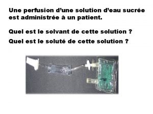
 Tubulure dialaflow
 Perfusion tisular
 Ficks law
 Twin anaemia polycythaemia sequence
 Perfusion tisular
 What is high quality cpr
 Alveolar dead space
 Perfusion
 Maligne fse
 Twin reversed arterial perfusion
 Presión de perfusión cerebral formula
 Chapter 22 respiratory system
 Kto perfusion
 Rojo rutilante
 Ct perfusion radiopedia
 La hora de oro
 Syndrome interstitiel diffus
 Cloison interalvéolaire
 Pontine respiratory group
 Intrapulmonary pressure is the
 Canadian society of clinical perfusion
 Information asset classification worksheet
 Threat vulnerability asset worksheet
 Information asset classification worksheet
 Ranked vulnerability risk worksheet
 Weighted factor analysis worksheet
 Weighted factor analysis worksheet
