MultiChannel Protocols for Wireless Mesh Networks YuChee Tseng

- Slides: 63
Multi-Channel Protocols for Wireless Mesh Networks Yu-Chee Tseng CS/NCTU 1
Outline Introduction to MANET n Review of 3 Multi-channel Protocols n Summary n 2
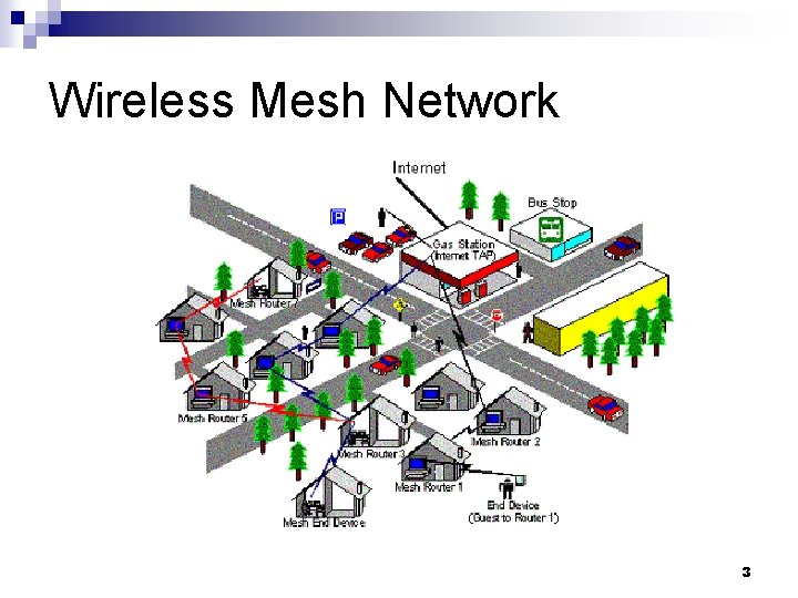
Wireless Mesh Network 3
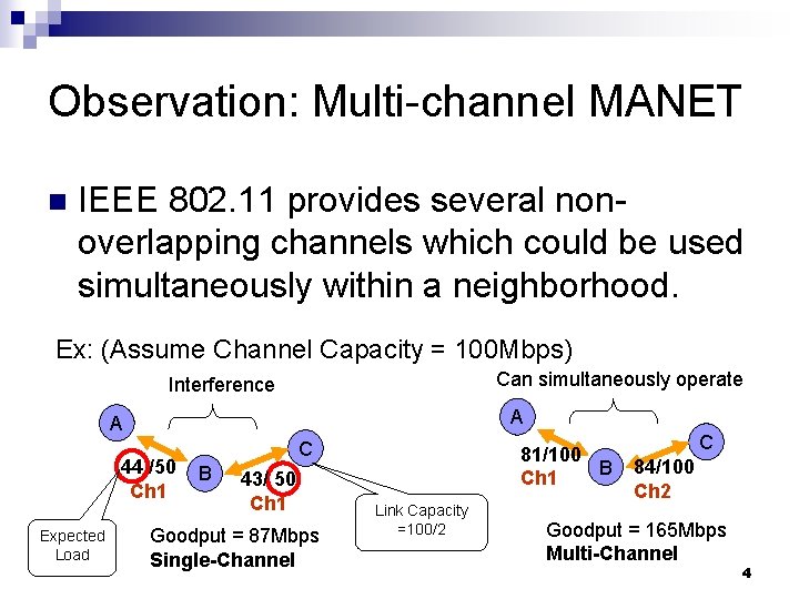
Observation: Multi-channel MANET n IEEE 802. 11 provides several nonoverlapping channels which could be used simultaneously within a neighborhood. Ex: (Assume Channel Capacity = 100 Mbps) Can simultaneously operate Interference A A 44 /50 Ch 1 Expected Load C B 43/ 50 Ch 1 Goodput = 87 Mbps Single-Channel 81/100 B Ch 1 Link Capacity =100/2 C 84/100 Ch 2 Goodput = 165 Mbps Multi-Channel 4
Motivation The idea of exploiting multiple channels is appealing in wireless mesh networks because of their high capacity requirements to support backbone traffic. n However, the channel assignment problem is NP-hard. n 5
A Multi-channel Example 6
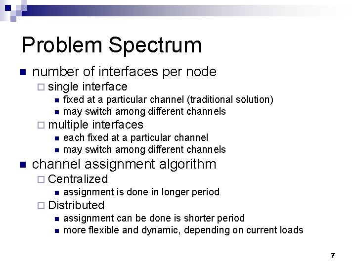
Problem Spectrum n number of interfaces per node ¨ single interface n fixed at a particular channel (traditional solution) n may switch among different channels ¨ multiple interfaces n each fixed at a particular channel n may switch among different channels n channel assignment algorithm ¨ Centralized n assignment is done in longer period ¨ Distributed n assignment can be done is shorter period n more flexible and dynamic, depending on current loads 7
Review 1: A Centralized Greedy Solution n Ashish Raniwala, Kartik Gopalan, and Tzi-cker Chiueh, “Centralized Channel Assignment and Routing Algorithms for Multi-Channel Wireless Mesh Networks, ” Mobile Computing and Communications Review, vol. 8, no. 2, pp. 50– 65, April 2004. 8
Problem Statement n Input: expected load on each link n Output: assignment of channels to network interfaces n Goal: to reduce interference between neighboring interfaces 9
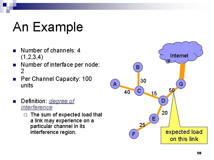
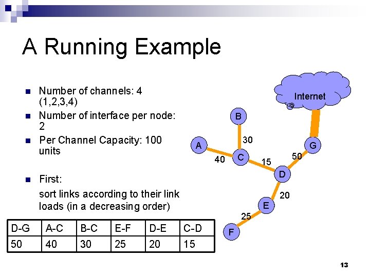
An Example n n n Number of channels: 4 (1, 2, 3, 4) Number of interface per node: 2 Per Channel Capacity: 100 units Internet B 30 A C 40 n G Definition: degree of interference ¨ The sum of expected load that a link may experience on a particular channel in its interference region. 50 15 D E 20 25 F expected load on this link 10
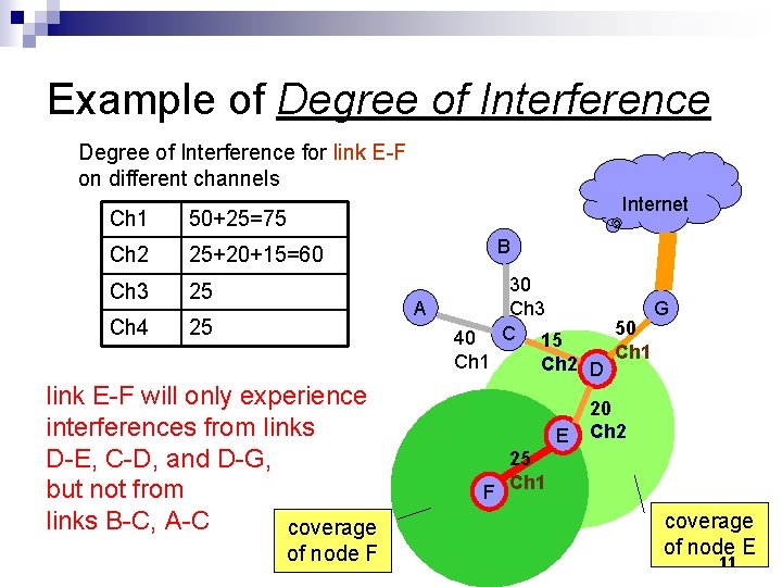
Example of Degree of Interference for link E-F on different channels Internet Ch 1 50+25=75 Ch 2 25+20+15=60 B Ch 3 25 Ch 4 25 30 Ch 3 C 15 A 40 Ch 1 link E-F will only experience interferences from links D-E, C-D, and D-G, but not from links B-C, A-C coverage of node F Ch 2 D E 50 Ch 1 G 20 Ch 2 25 F Ch 1 coverage of node E 11
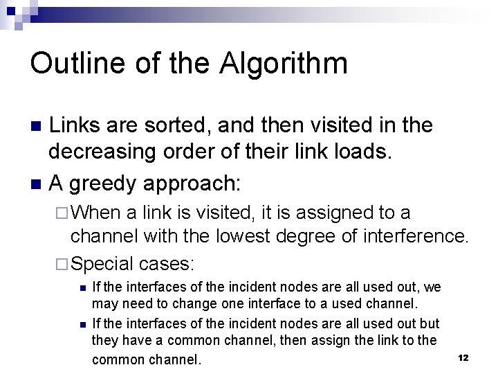
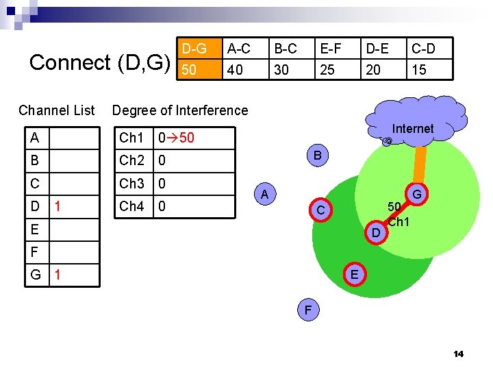
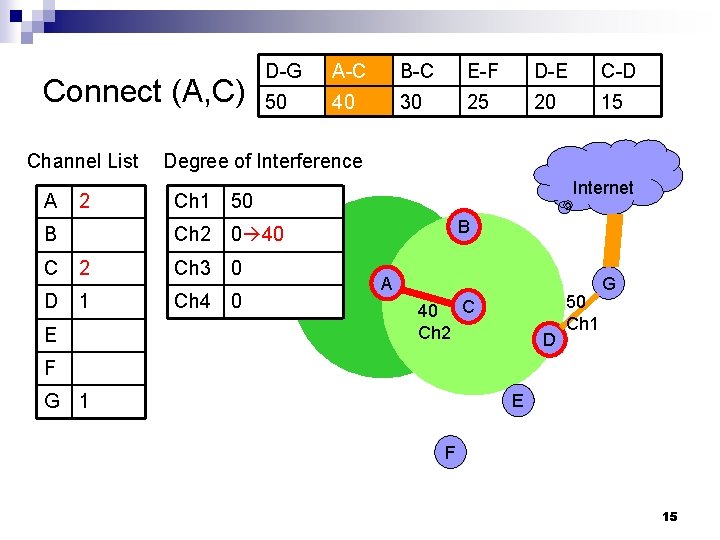
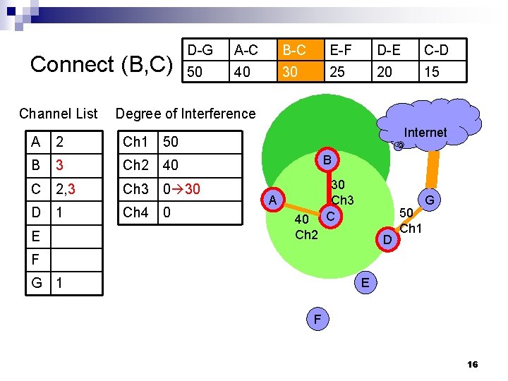
Outline of the Algorithm Links are sorted, and then visited in the decreasing order of their link loads. n A greedy approach: n ¨ When a link is visited, it is assigned to a channel with the lowest degree of interference. ¨ Special cases: n n If the interfaces of the incident nodes are all used out, we may need to change one interface to a used channel. If the interfaces of the incident nodes are all used out but they have a common channel, then assign the link to the common channel. 12
A Running Example n n Number of channels: 4 (1, 2, 3, 4) Number of interface per node: 2 Per Channel Capacity: 100 units Internet B 30 A C 40 G 50 15 D First: sort links according to their link loads (in a decreasing order) E 20 25 D-G A-C B-C E-F D-E C-D 50 40 30 25 20 15 F 13
Connect (D, G) Channel List D-G A-C B-C E-F D-E C-D 50 40 30 25 20 15 Degree of Interference A Ch 1 0 50 B Ch 2 0 C Ch 3 0 D 1 Ch 4 0 Internet B A C E D 50 Ch 1 G F G 1 E F 14
Connect (A, C) Channel List A 2 D-G A-C B-C E-F D-E C-D 50 40 30 25 20 15 Degree of Interference Internet Ch 1 50 B Ch 2 0 40 B C 2 Ch 3 0 D 1 Ch 4 0 E A 40 C Ch 2 D 50 Ch 1 G F G 1 E F 15
Connect (B, C) Channel List D-G A-C B-C E-F D-E C-D 50 40 30 25 20 15 Degree of Interference Internet A 2 Ch 1 50 B 3 Ch 2 40 B C 2, 3 Ch 3 0 30 D 1 Ch 4 0 30 Ch 3 C E A 40 Ch 2 D 50 Ch 1 G F G 1 E F 16
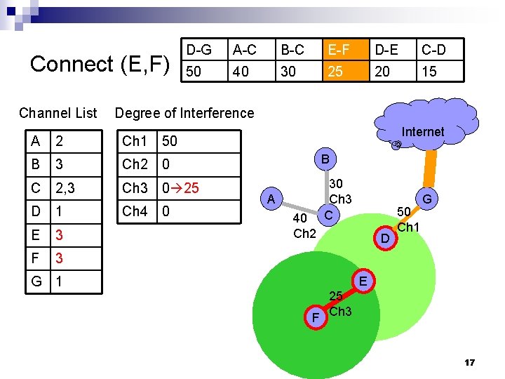
Connect (E, F) Channel List D-G A-C B-C E-F D-E C-D 50 40 30 25 20 15 Degree of Interference Internet A 2 Ch 1 50 B 3 Ch 2 0 B C 2, 3 Ch 3 0 25 D 1 Ch 4 0 30 Ch 3 C E 3 F 3 G 1 A 40 Ch 2 D 50 Ch 1 G E 25 F Ch 3 17
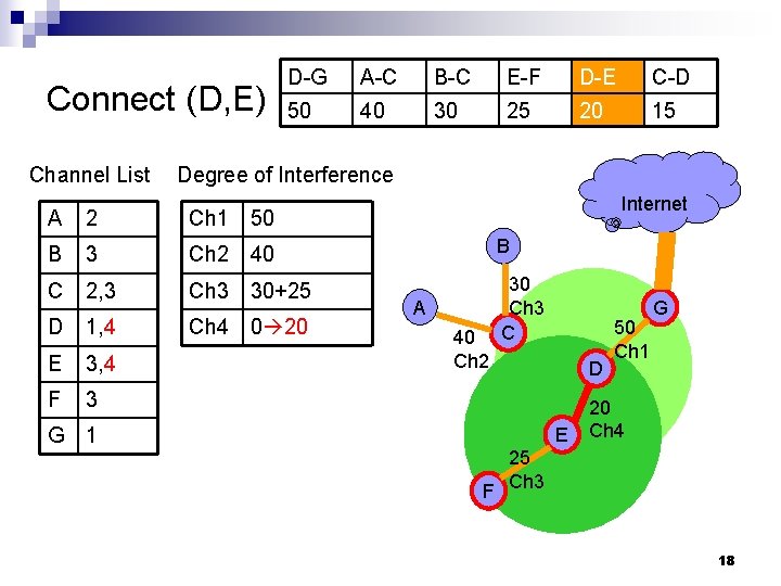
Connect (D, E) Channel List D-G A-C B-C E-F D-E C-D 50 40 30 25 20 15 Degree of Interference Internet A 2 Ch 1 50 B 3 Ch 2 40 B C 2, 3 Ch 3 30+25 D 1, 4 Ch 4 0 20 30 Ch 3 C E 3, 4 F 3 G 1 A 40 Ch 2 D E 50 Ch 1 G 20 Ch 4 25 F Ch 3 18
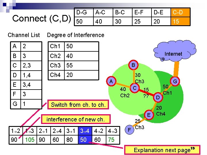
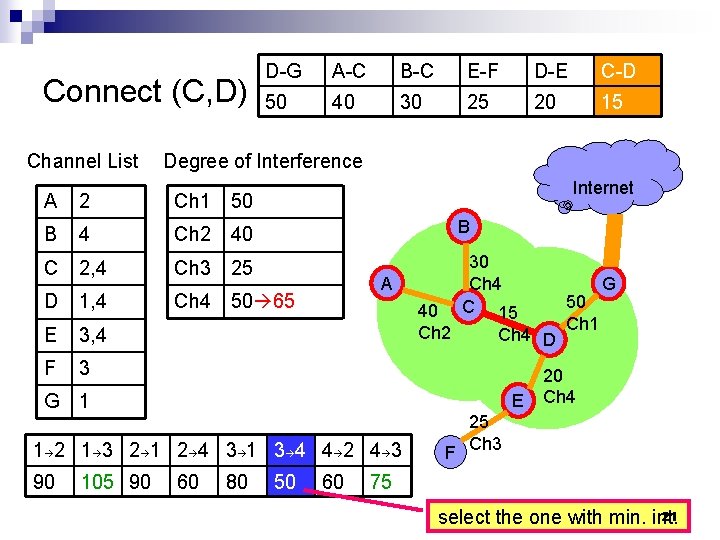
Connect (C, D) Channel List D-G A-C B-C E-F D-E C-D 50 40 30 25 20 15 Degree of Interference A 2 Ch 1 50 B 3 Ch 2 40 C 2, 3 Ch 3 55 B D 1, 4 Ch 4 20 E 3, 4 F 3 30 Ch 3 C 15 G 1 Internet A 40 Ch 2 Switch from ch. to ch. E interference of new ch. 1 2 1 3 2 1 2 4 3 1 3 4 4 2 4 3 90 105 90 ? ? 60 80 50 60 D 50 Ch 1 G 20 Ch 4 25 F Ch 3 75 Explanation next page 19
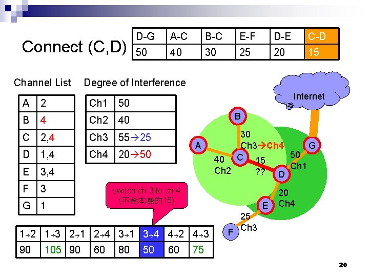
Connect (C, D) Channel List D-G A-C B-C E-F D-E C-D 50 40 30 25 20 15 Degree of Interference Internet A 2 Ch 1 50 B 4 Ch 2 40 C 2, 4 Ch 3 55 25 D 1, 4 Ch 4 20 50 E 3, 4 F 3 B A switch ch 3 to ch 4 (不含本身的15) G 1 E 1 2 1 3 2 1 2 4 3 1 3 4 4 2 4 3 90 105 90 30 G Ch 3 Ch 4 50 40 C 15 Ch 1 Ch 2 ? ? D 60 80 50 60 20 Ch 4 25 F Ch 3 75 20
Connect (C, D) Channel List D-G A-C B-C E-F D-E C-D 50 40 30 25 20 15 Degree of Interference Internet A 2 Ch 1 50 B 4 Ch 2 40 B C 2, 4 Ch 3 25 D 1, 4 Ch 4 50 65 30 Ch 4 C 15 E 3, 4 F 3 A 40 Ch 2 G 1 E 1 2 1 3 2 1 2 4 3 1 3 4 4 2 4 3 90 105 90 Ch 4 D 60 80 50 60 50 Ch 1 G 20 Ch 4 25 F Ch 3 75 21 select the one with min. int.
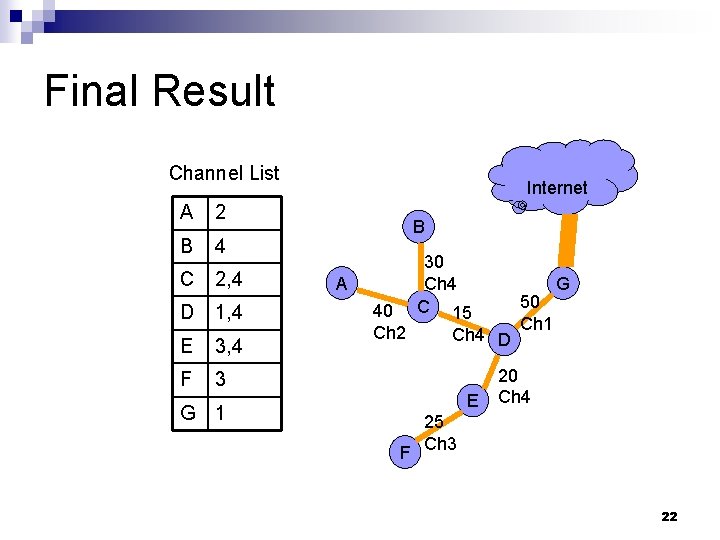
Final Result Channel List A 2 B 4 C 2, 4 D 1, 4 E 3, 4 F 3 G 1 Internet B A 40 Ch 2 30 Ch 4 C 15 Ch 4 D E 50 Ch 1 G 20 Ch 4 25 F Ch 3 22
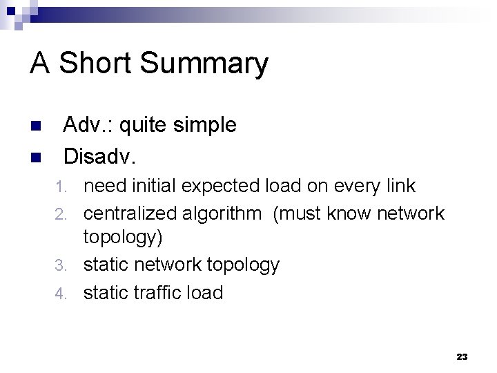
A Short Summary n n Adv. : quite simple Disadv. need initial expected load on every link 2. centralized algorithm (must know network topology) 3. static network topology 4. static traffic load 1. 23
Review 2: (SSCH) A distributed, single-interface solution n Paramvir Bahl, Ranveer Chandra, and John Dunagan, “SSCH: Slotted Seeded Channel Hopping for Capacity Improvement in IEEE 802. 11 Ad-Hoc Wireless Networks, ” in ACM Mobicom, 2004. 24
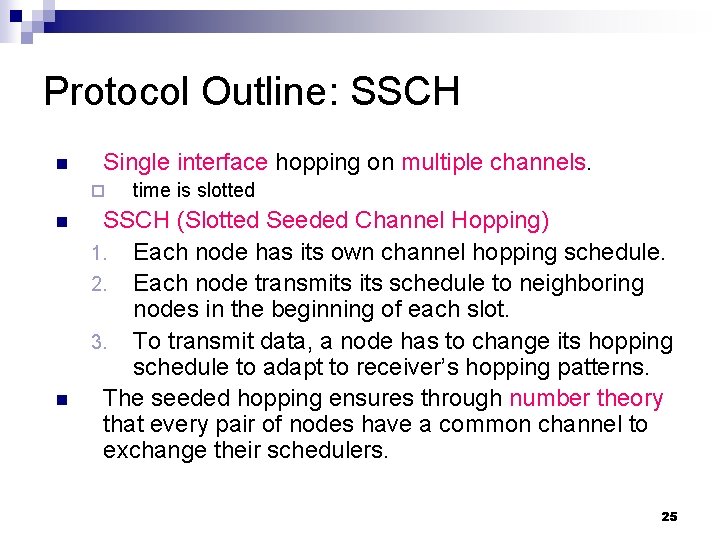
Protocol Outline: SSCH n Single interface hopping on multiple channels. ¨ n n time is slotted SSCH (Slotted Seeded Channel Hopping) 1. Each node has its own channel hopping schedule. 2. Each node transmits schedule to neighboring nodes in the beginning of each slot. 3. To transmit data, a node has to change its hopping schedule to adapt to receiver’s hopping patterns. The seeded hopping ensures through number theory that every pair of nodes have a common channel to exchange their schedulers. 25
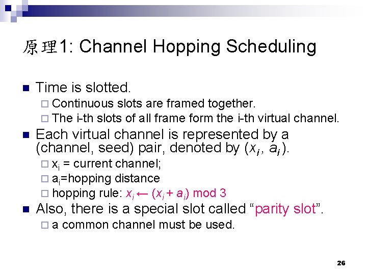
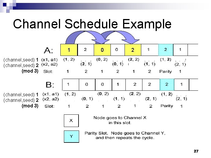
原理1: Channel Hopping Scheduling n Time is slotted. ¨ Continuous slots are framed together. ¨ The i-th slots of all frame form the i-th virtual channel. n Each virtual channel is represented by a (channel, seed) pair, denoted by (xi , ai ). ¨ xi = current channel; ¨ ai=hopping distance ¨ hopping rule: xi ← (xi + ai) mod 3 n Also, there is a special slot called “parity slot”. ¨ a common channel must be used. 26
Channel Schedule Example 1 0 2 (channel, seed) 1 (channel, seed) 2 (mod 3) 27
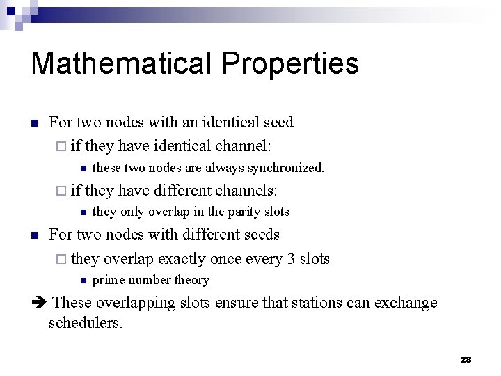
Mathematical Properties n For two nodes with an identical seed ¨ if they have identical channel: n ¨ if they have different channels: n n these two nodes are always synchronized. they only overlap in the parity slots For two nodes with different seeds ¨ they overlap exactly once every 3 slots n prime number theory These overlapping slots ensure that stations can exchange schedulers. 28
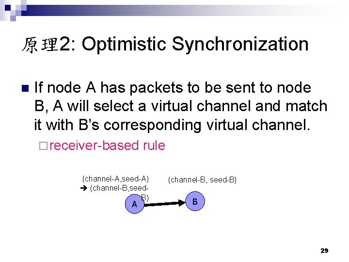
原理2: Optimistic Synchronization n If node A has packets to be sent to node B, A will select a virtual channel and match it with B’s corresponding virtual channel. ¨ receiver-based rule (channel-A, seed-A) (channel-B, seed. B) A (channel-B, seed-B) B 29
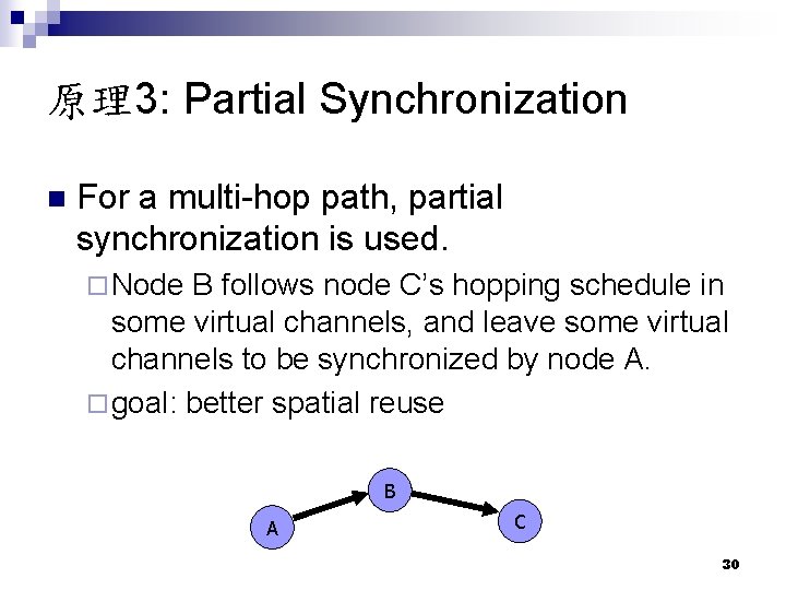
原理3: Partial Synchronization n For a multi-hop path, partial synchronization is used. ¨ Node B follows node C’s hopping schedule in some virtual channels, and leave some virtual channels to be synchronized by node A. ¨ goal: better spatial reuse B A C 30
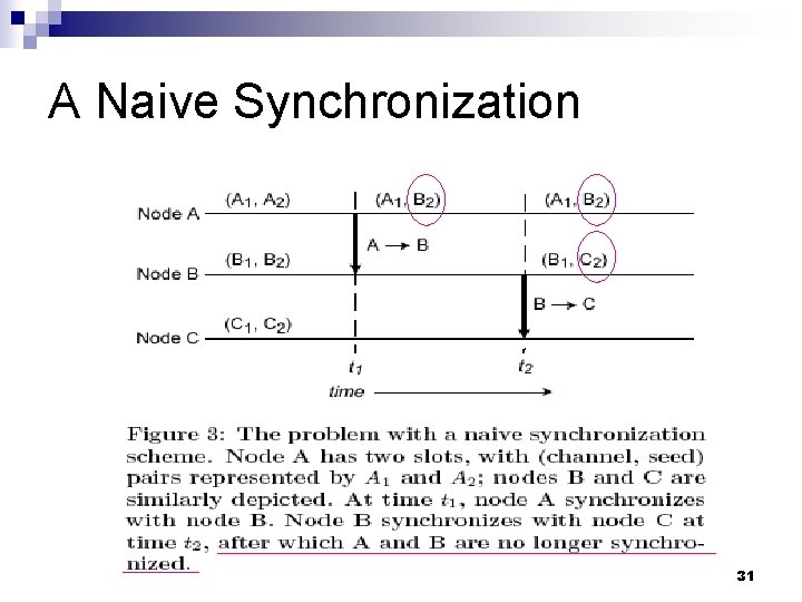
A Naive Synchronization 31
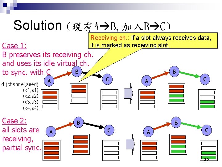
Solution (現有A B, 加入B C) Receiving ch. : If a slot always receives data, it is marked as receiving slot. Case 1: B preserves its receiving ch. and uses its idle virtual ch. B to sync. with C 4 (channel, seed) (x 1, a 1) (x 2, a 2) (x 3, a 3) (x 4, a 4) Case 2: all slots are receiving, partial sync. A B C B A C A B C A C 32
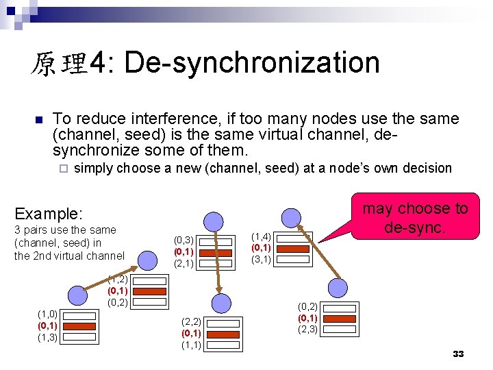
原理4: De-synchronization n To reduce interference, if too many nodes use the same (channel, seed) is the same virtual channel, desynchronize some of them. ¨ simply choose a new (channel, seed) at a node’s own decision may choose to de-sync. Example: 3 pairs use the same (channel, seed) in the 2 nd virtual channel (0, 3) (0, 1) (2, 1) (1, 2) (0, 1) (0, 2) (1, 0) (0, 1) (1, 3) (2, 2) (0, 1) (1, 4) (0, 1) (3, 1) (0, 2) (0, 1) (2, 3) 33
Short Summary n Adv. 1. 2. n an interesting partial synchronization technique an interesting de-synchronization technique Disadv. 1. 2. need global time synchronization only designed for one interface 34
Review 3: (MCR) A multi-interface channel assignment protocol n Pradeep Kyasanur and Nitin H. Vaidya, "Routing and Interface Assignment in Multi-Channel Multi. Interface Wireless Networks", WCNC 2005. 35
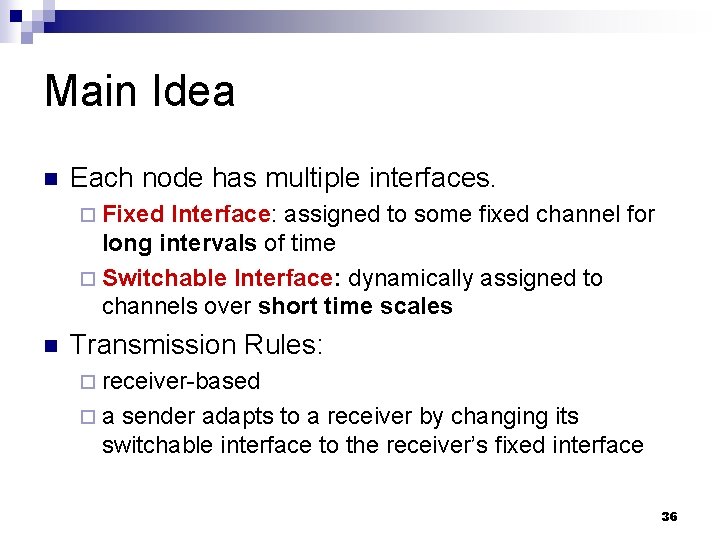
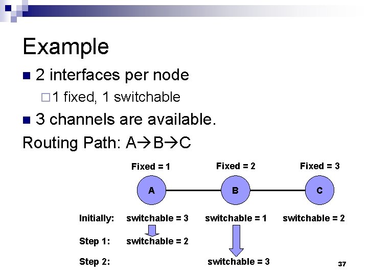
Main Idea n Each node has multiple interfaces. ¨ Fixed Interface: assigned to some fixed channel for long intervals of time ¨ Switchable Interface: dynamically assigned to channels over short time scales n Transmission Rules: ¨ receiver-based ¨ a sender adapts to a receiver by changing its switchable interface to the receiver’s fixed interface 36
Example n 2 interfaces per node ¨ 1 fixed, 1 switchable 3 channels are available. Routing Path: A B C n Fixed = 1 Fixed = 2 Fixed = 3 A B C Initially: switchable = 3 Step 1: switchable = 2 Step 2: switchable = 1 switchable = 3 switchable = 2 37
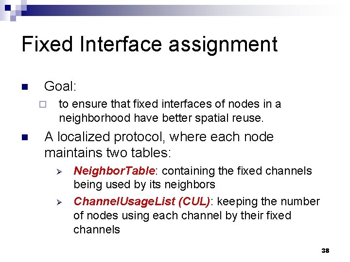
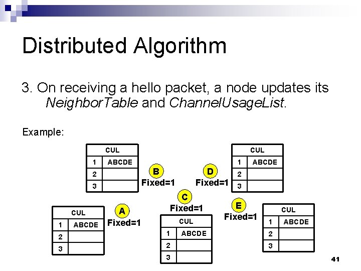
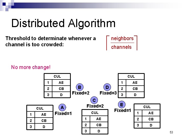
Fixed Interface assignment n Goal: ¨ n to ensure that fixed interfaces of nodes in a neighborhood have better spatial reuse. A localized protocol, where each node maintains two tables: Ø Ø Neighbor. Table: containing the fixed channels being used by its neighbors Channel. Usage. List (CUL): keeping the number of nodes using each channel by their fixed channels 38
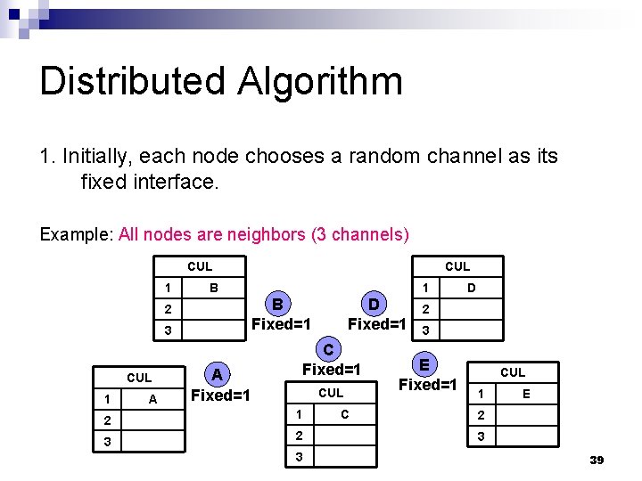
Distributed Algorithm 1. Initially, each node chooses a random channel as its fixed interface. Example: All nodes are neighbors (3 channels) CUL 1 B 3 1 A 1 B Fixed=1 2 CUL A Fixed=1 D Fixed=1 CUL 2 1 3 2 3 C D 2 3 E Fixed=1 CUL 1 E 2 3 39
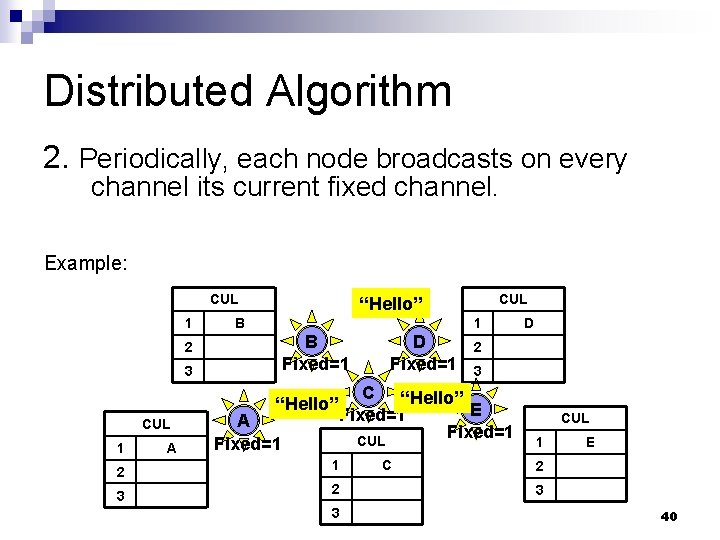
Distributed Algorithm 2. Periodically, each node broadcasts on every channel its current fixed channel. Example: CUL 1 B Fixed=1 2 3 “Hello” CUL 1 A CUL “Hello” A Fixed=1 D Fixed=1 2 3 C “Hello” E Fixed=1 CUL 2 1 3 2 3 C D CUL 1 E 2 3 40
Distributed Algorithm 3. On receiving a hello packet, a node updates its Neighbor. Table and Channel. Usage. List. Example: CUL 1 ABCDE 3 1 ABCDE 1 B Fixed=1 2 CUL A Fixed=1 D Fixed=1 CUL 2 1 3 2 3 ABCDE 2 3 E Fixed=1 CUL 1 ABCDE 2 3 41
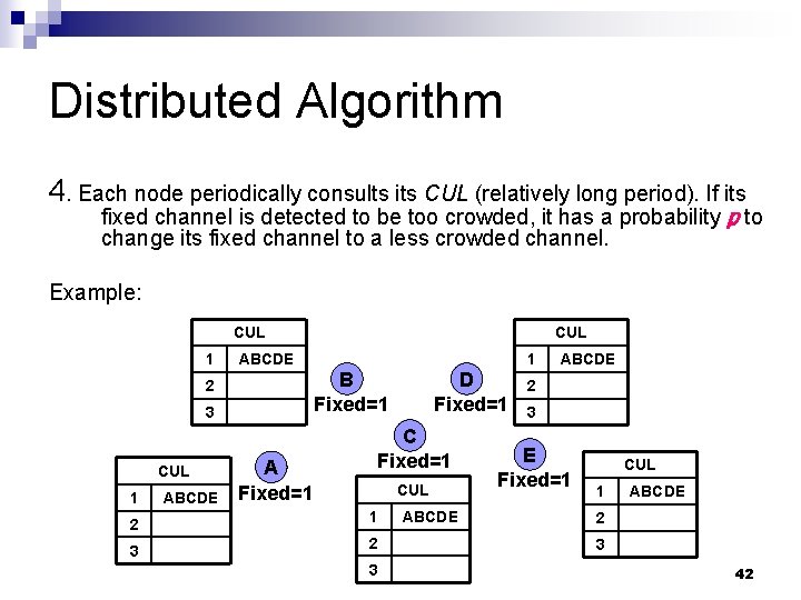
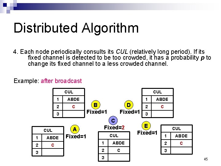
Distributed Algorithm 4. Each node periodically consults its CUL (relatively long period). If its fixed channel is detected to be too crowded, it has a probability p to change its fixed channel to a less crowded channel. Example: CUL 1 ABCDE 3 1 ABCDE 1 B Fixed=1 2 CUL A Fixed=1 D Fixed=1 CUL 2 1 3 2 3 ABCDE 2 3 E Fixed=1 CUL 1 ABCDE 2 3 42
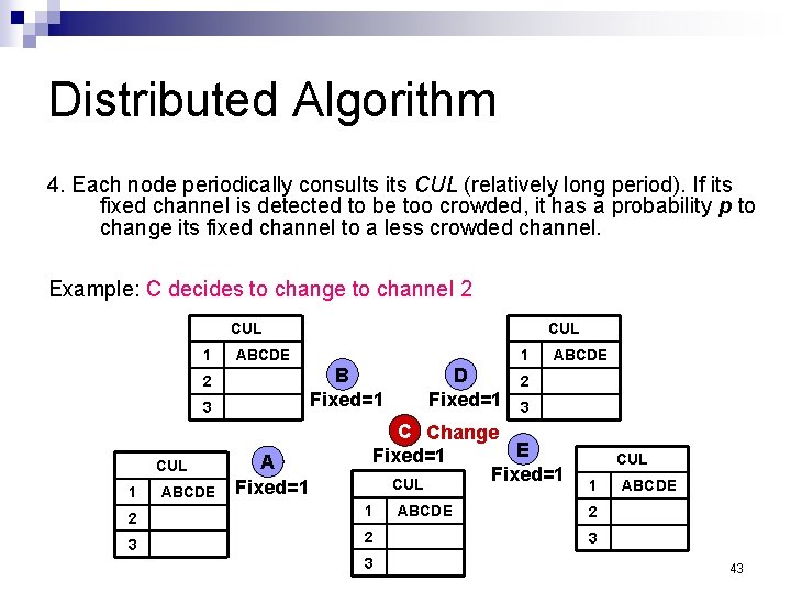
Distributed Algorithm 4. Each node periodically consults its CUL (relatively long period). If its fixed channel is detected to be too crowded, it has a probability p to change its fixed channel to a less crowded channel. Example: C decides to change to channel 2 CUL 1 ABCDE 3 1 ABCDE 1 B Fixed=1 2 CUL A Fixed=1 D Fixed=1 ABCDE 2 3 C Change E Fixed=1 CUL 2 1 3 2 3 ABCDE CUL 1 ABCDE 2 3 43
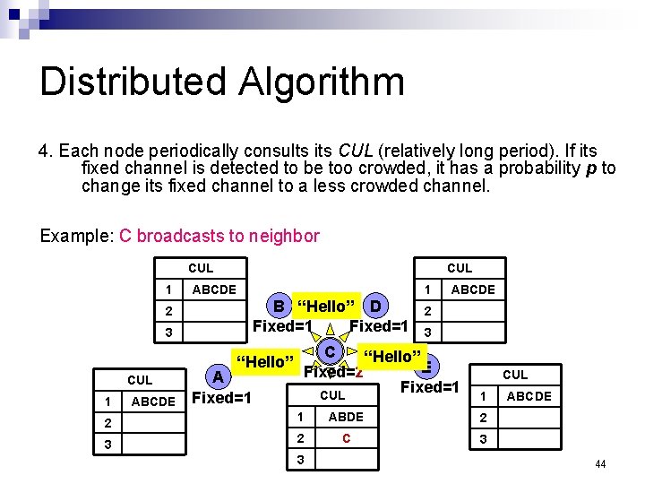
Distributed Algorithm 4. Each node periodically consults its CUL (relatively long period). If its fixed channel is detected to be too crowded, it has a probability p to change its fixed channel to a less crowded channel. Example: C broadcasts to neighbor CUL 1 CUL ABCDE 1 B “Hello” D Fixed=1 2 3 “Hello” CUL 1 ABCDE A Fixed=1 ABCDE 2 3 C “Hello” E Fixed=2 Fixed=1 CUL 1 2 1 ABDE 2 3 2 C 3 3 ABCDE 44
Distributed Algorithm 4. Each node periodically consults its CUL (relatively long period). If its fixed channel is detected to be too crowded, it has a probability p to change its fixed channel to a less crowded channel. Example: after broadcast CUL 1 ABDE 2 C 3 A Fixed=1 CUL B Fixed=1 D Fixed=1 C Fixed=2 CUL 1 ABDE 2 C 3 E Fixed=1 CUL 1 ABDE C 1 ABDE 2 2 C 3 3 45
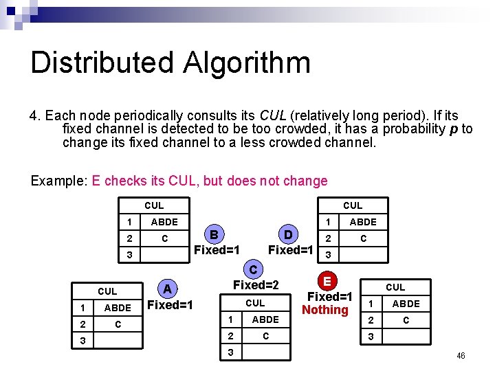
Distributed Algorithm 4. Each node periodically consults its CUL (relatively long period). If its fixed channel is detected to be too crowded, it has a probability p to change its fixed channel to a less crowded channel. Example: E checks its CUL, but does not change CUL 1 ABDE 2 C 3 A Fixed=1 CUL B Fixed=1 D Fixed=1 C Fixed=2 CUL 1 ABDE 2 C 3 E Fixed=1 Nothing CUL 1 ABDE 2 C 3 46
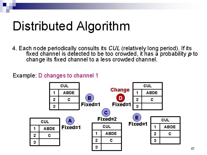
Distributed Algorithm 4. Each node periodically consults its CUL (relatively long period). If its fixed channel is detected to be too crowded, it has a probability p to change its fixed channel to a less crowded channel. Example: D changes to channel 1 CUL 1 ABDE 2 C 3 A Fixed=1 Change B Fixed=1 D Fixed=1 C Fixed=2 CUL 1 ABDE 2 C 3 E Fixed=1 CUL 1 ABDE C 1 ABDE 2 2 C 3 3 47
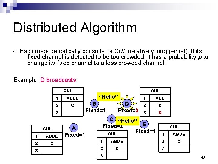
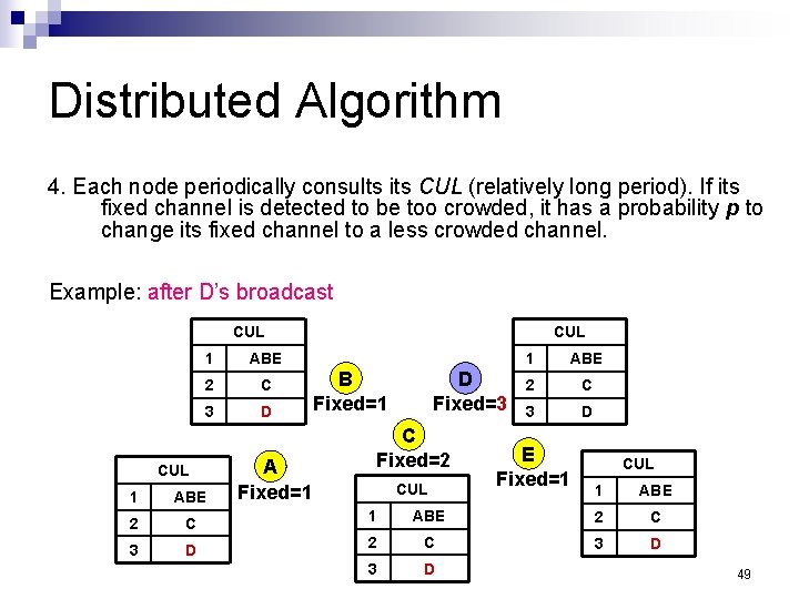
Distributed Algorithm 4. Each node periodically consults its CUL (relatively long period). If its fixed channel is detected to be too crowded, it has a probability p to change its fixed channel to a less crowded channel. Example: D broadcasts CUL 1 ABDE 2 C 3 A Fixed=1 CUL “Hello” B Fixed=1 D Fixed=3 1 ABE 2 C 3 D C “Hello” E Fixed=2 Fixed=1 CUL 1 ABDE C 1 ABDE 2 2 C 3 3 48
Distributed Algorithm 4. Each node periodically consults its CUL (relatively long period). If its fixed channel is detected to be too crowded, it has a probability p to change its fixed channel to a less crowded channel. Example: after D’s broadcast CUL 1 ABE 2 C 3 D CUL A Fixed=1 CUL B Fixed=1 D Fixed=3 C Fixed=2 CUL 1 ABE 2 C 3 D E Fixed=1 CUL 1 ABE 2 C 3 D 1 ABE 2 C 1 3 D 49
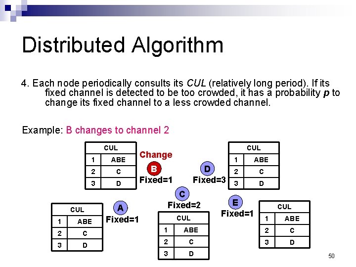
Distributed Algorithm 4. Each node periodically consults its CUL (relatively long period). If its fixed channel is detected to be too crowded, it has a probability p to change its fixed channel to a less crowded channel. Example: B changes to channel 2 CUL 1 ABE 2 C 3 D CUL A Fixed=1 CUL Change B Fixed=1 D Fixed=3 C Fixed=2 CUL 1 ABE 2 C 3 D E Fixed=1 CUL 1 ABE 2 C 3 D 1 ABE 2 C 1 3 D 50
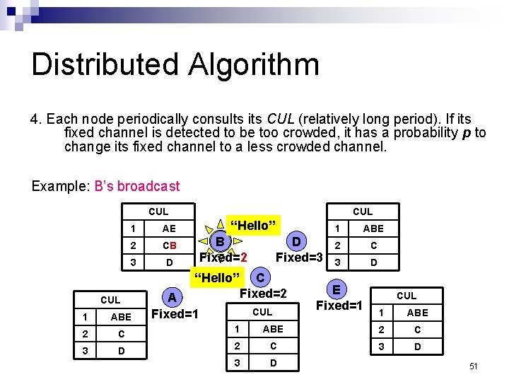
Distributed Algorithm 4. Each node periodically consults its CUL (relatively long period). If its fixed channel is detected to be too crowded, it has a probability p to change its fixed channel to a less crowded channel. Example: B’s broadcast CUL 1 AE 2 CB 3 D CUL “Hello” B Fixed=2 “Hello” CUL A Fixed=1 D Fixed=3 C Fixed=2 CUL 1 ABE 2 C 3 D E Fixed=1 CUL 1 ABE 2 C 3 D 1 ABE 2 C 1 3 D 51
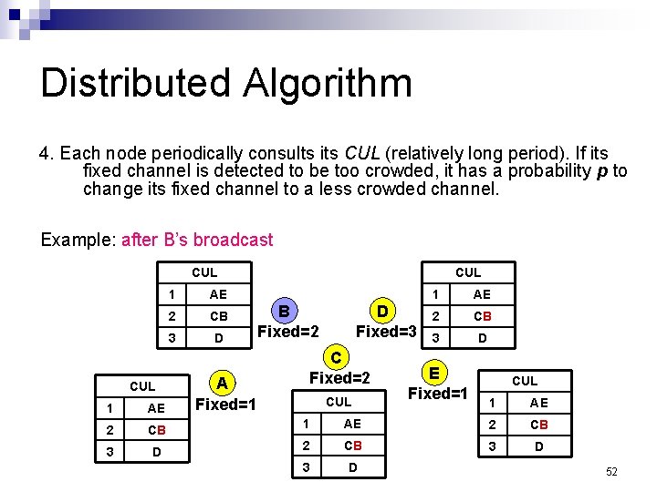
Distributed Algorithm 4. Each node periodically consults its CUL (relatively long period). If its fixed channel is detected to be too crowded, it has a probability p to change its fixed channel to a less crowded channel. Example: after B’s broadcast CUL 1 AE 2 CB 3 D A Fixed=1 CUL B Fixed=2 D Fixed=3 C Fixed=2 CUL 1 AE 2 CB 3 D E Fixed=1 CUL 1 AE AE 2 CB 3 D 1 AE 2 CB 1 3 D 52
Distributed Algorithm Threshold to determinate whenever a channel is too crowded: neighbors channels No more change! CUL 1 AE 2 CB 3 D A Fixed=1 CUL B Fixed=2 D Fixed=3 C Fixed=2 CUL 1 AE 2 CB 3 D E Fixed=1 CUL 1 AE AE 2 CB 3 D 1 AE 2 CB 1 3 D 53
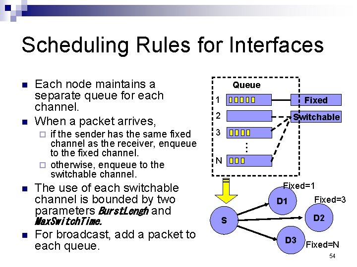
Scheduling Rules for Interfaces n n Each node maintains a separate queue for each channel. When a packet arrives, n The use of each switchable channel is bounded by two parameters Burst. Lengh and Max. Switch. Time. n For broadcast, add a packet to each queue. 1 Fixed 2 Switchable 3 … if the sender has the same fixed channel as the receiver, enqueue to the fixed channel. ¨ otherwise, enqueue to the switchable channel. ¨ Queue N Fixed=1 D 1 Fixed=3 D 2 S D 3 Fixed=N 54
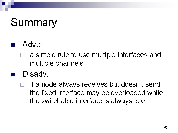
Summary n Adv. : ¨ n a simple rule to use multiple interfaces and multiple channels Disadv. ¨ If a node always receives but doesn’t send, the fixed interface may be overloaded while the switchable interface is always idle. 55
Review 4: A multi-interface routing protocol n Richard Draves, Jitendra Padhye, and Brian Zill, “Routing in Multi- Radio, Multi-Hop Wireless Mesh Networks, ” in ACM Mobicom, 2004. 56
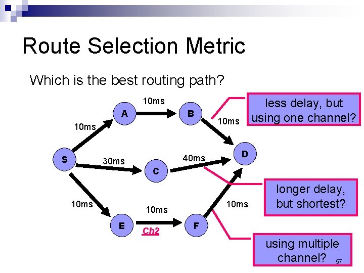
Route Selection Metric Which is the best routing path? 10 ms A B 10 ms S 30 ms 10 ms 40 ms 10 ms D C 10 ms E less delay, but using one channel? Ch 2 longer delay, but shortest? F using multiple channel? 57
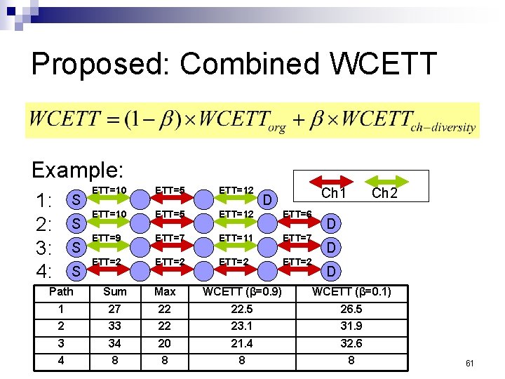
How to Select a Good Path n A good routing protocol should take the loss rate, the bandwidth of a link, and channel diversity into account. ¨ For a multi-channel MANET, the path metric should explicitly account for the interference among links that operate on the same channel. n Multi-Radio Link-Quality Source Routing ¨ a combination of the LQSR protocol with a new metric that we call WCETT (Weighted Cumulative Expected Transmission Time). 58
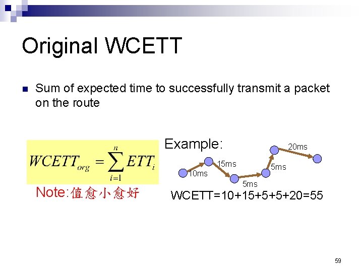
Original WCETT n Sum of expected time to successfully transmit a packet on the route Example: 20 ms 15 ms 10 ms Note: 值愈小愈好 5 ms WCETT=10+15+5+5+20=55 59
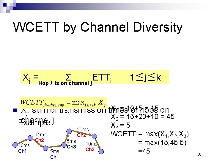
WCETT by Channel Diversity Xj =Hop i n Σ ETT i is on channel j 1≦j≦k X 1 = 10+5 = 15 Xj: sum of transmission times of hops on X 2 = 15+20+10 = 45 channel j Example: X = 5 10 ms Ch 1 20 ms Ch 2 15 ms Ch 2 5 ms Ch 1 5 ms Ch 3 10 ms Ch 2 3 WCETT = max(X 1, X 2, X 3) = max(15, 45, 5) =45 60
Proposed: Combined WCETT Example: 1: 2: 3: 4: S S ETT=10 ETT=5 ETT=12 ETT=6 ETT=9 ETT=7 ETT=11 ETT=7 ETT=2 Ch 1 D Ch 2 D D D Path Sum Max WCETT (β=0. 9) WCETT (β=0. 1) 1 27 22 22. 5 26. 5 2 33 22 23. 1 31. 9 3 34 20 21. 4 32. 6 4 8 8 61
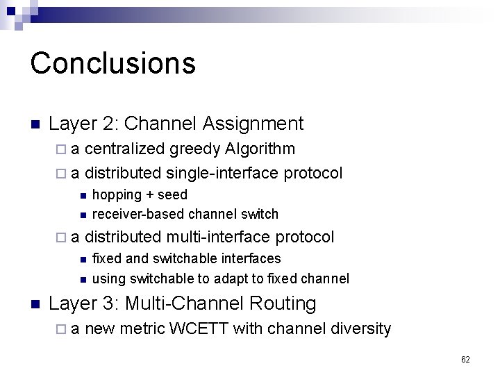
Conclusions n Layer 2: Channel Assignment ¨ a centralized greedy Algorithm ¨ a distributed single-interface protocol n n hopping + seed receiver-based channel switch ¨ a distributed multi-interface protocol n n n fixed and switchable interfaces using switchable to adapt to fixed channel Layer 3: Multi-Channel Routing ¨ a new metric WCETT with channel diversity 62
References 1. 2. 3. 4. 5. Ashish Raniwala, Kartik Gopalan, and Tzi-cker Chiueh, “Centralized Channel Assignment and Routing Algorithms for Multi-Channel Wireless Mesh Networks, ” Mobile Computing and Communications Review, vol. 8, no. 2, pp. 50– 65, April 2004. Paramvir Bahl, Ranveer Chandra, and John Dunagan, “SSCH: Slotted Seeded Channel Hopping for Capacity Improvement in IEEE 802. 11 Ad. Hoc Wireless Networks, ” in ACM Mobicom, 2004. Pradeep Kyasanur and Nitin H. Vaidya, "Routing and Interface Assignment in Multi-Channel Multi-Interface Wireless Networks", Technical Report, October 2004 (A version will appear in WCNC 2005) Richard Draves, Jitendra Padhye, and Brian Zill, “Routing in Multi- Radio, Multi-Hop Wireless Mesh Networks, ” in ACM Mobicom, 2004. Shih-Lin Wu, Chih-Yu Lin, Yu-Chee Tseng, and Jang-Ping Sheu, “A New Multi-Channel MAC Protocol with On-Demand Channel Assignment for Multi-Hop Mobile Ad Hoc Networks, ” in International Symposium on Parallel Architectures, Algorithms and Networks (ISPAN), 2000. 63