COMPUTER NETWORKS UNIT 3 Data Link Layer CONTENTS


 A Packets Data link Layer Frames 1 2 2 1 (b) 1 2")
Data Link Control – Whenever an exchange of information between two devices")
 Services provided by the Data Link Layer – • Packetizing • Addressing •")
 Unacknowledged Connectionless Service – Source machine sends frames to destination machine but the")

An unrestricted simplex protocol – - Data is")


 Carrier sense multiple access with collision detection (CSMA/CD) is a")

 • Token bus is a network implementing the token")

 • Token ring local area network (LAN) technology is")


 bits with data.")


- Slides: 35
COMPUTER NETWORKS
UNIT 3 Data Link Layer
CONTENTS • Design Issues • Elementary Data Link Protocols • Static & Dynamic Channel Allocation • Introduction to IEEE Standards • Sliding Window Protocol • Error Detection & Correction Codes
INTRODUCTION • Provides a well-defined service interface to the network layer. • Determines how the bits of the physical layer are grouped into frames (framing). • Deals with transmission errors (CRC and ARQ). • Regulates the flow of frames. • Performs general link layer management.
(a) A Packets Data link Layer Frames 1 2 2 1 (b) 1 2 3 2 1 Medium 1 2 3 B 2 1 A 1 2 B Physical Layer Physical layer entity Data link layer entity 3 Data Link Layer 2 1 Network layer entity 5
DESIGN ISSUES 1)Data Link Control – Whenever an exchange of information between two devices is required, an interconnecting transmission medium between the two devices is also required. This medium or line carries electrical signals. At the same time a standard interface and a mechanism to convert binary digits into electrical signals is also required. Once the information is transmitted and received at the other end it should be checked for errors. So there should be some mechanism to control the transmission errors. This error and flow control mechanism is called Data Link Control or Data Flow Control. (To be continued)
2) Services provided by the Data Link Layer – • Packetizing • Addressing • Error Control • Flow Control • Access Control • Framing (To be continued)
3) Unacknowledged Connectionless Service – Source machine sends frames to destination machine but the destination machine doesn't send any acknowledgement of these frames back to the source. Hence it is called unacknowledged connectionless service. There is no error control mechanism in this service 4) Acknowledged connection oriented service – This type of service guarantees that packet or frame reaches the destination i. e acknowledgement is necessary in this type of service. Connection is established between source and destination before any data is transferred.
ELEMENTARY DATA LINK PROTOCOLS Computes the checksum. If checksum does not match send error message. If checksum is ok notify sending data link layer. Check all header trailer information. If all OK strip off the header and trailer and pass the packet to the data link layer. • A Frame composes of four fields – - Kind - Seq - Ack - Info • • • (To be continued)
TYPES OF ELEMENTARY DATA LINK PROTOCOLS 1)An unrestricted simplex protocol – - Data is transmitted in one direction only. - Both sender & receiver network layers are ready. - Processing time can be ignored. - Infinite buffer space is available. - Communication between data link layer never damages or looses frames. 2)A Simplex Stop & Wait protocol – Protocol in which the sender sends one frame and then waits for an acknowledgement before proceeding is called Stop and Wait protocol.
STATIC CHANNEL ALLOCATION • A channel once allocated to a particular device is not allocated to any other device in any case. That portion of the channel is dedicated to that particular device. • A single channel is divided among various users either on the basis of frequency or on the basis of time. • For static channel allocation, there are two methods available - FDM (Frequency Division Multiplexing) - TDM (Time Division Multiplexing)
DYNAMIC CHANNEL ALLOCATION • Rather than allocating a channel in a fixed manner, the channel is allocated dynamically as per the user requirements. • Once the channel is allocated, allocation can also be altered based on changing environment. • None of the users is assigned fixed frequency or fixed time slot. • A portion of a channel is not dedicated to a particular device. (To be continued)
DYNAMIC CHANNEL ALLOCATION ASSUMPTIONS • Independent Stations. • Single channel • Collision • Time continuity • Carrier sense • No carrier sense.
SLIDING WINDOW PROTOCOLS • Sliding window protocol is a data transmission protocol used in the data link layer of OSI model • For full duplex two transmission lines are required. • One to send data and the other to receive data and/or ACKs. • Sending ACKs in a packet of its own is waste of resources. • May use piggybacking. • The acknowledgement is attached to an outgoing data frame(ack field in the frame header). • Data link layer must wait until it has some thing to send before it can ack. • This may cause time out and the frame may be re-sent. (To be continued)
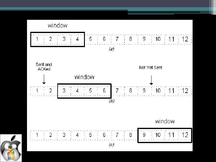
• The essence of sliding window protocols is that at any instant of time, the sender maintains a set of sequence numbers corresponding to frames it is permitted to send. These frames are said to fall within the sending window. Similarly, the receiver also maintains a receiving window corresponding to the set of frames it is permitted to accept. It is NOT necessary for the sender and receiver to have same number limits. • Sequence numbers of frames sent but not acknowledged are kept in the senders window. • The receivers window corresponds to the frames it may accept. • The sequence numbers within the sender window represents frames that have been sent or can be sent.
TYPES OF SLIDING WINDOW PROTOCOLS One Bit Sliding Window protocol - The sender sends out one frame, waits for acknowledgement before sending next frame. - This protocol transmits a PDU of information and then waits for its response. - The receiver receives each PDU and sends an ACK if PDU is received correctly. A Protocol using Go-Back-N - The sender can send N frames at a time without waiting for acknowledgement and keeping the copy of each transmitted frame till the acknowledgement is received. Go Back N manages two windows - - Sender’s window - Receiver’s window
IEEE STANDARDS • IEEE stands for Institute of Electrical and Electronic Engineers. • For network developers and network users, a idea of network standard and protocols is must. So the need of network standards and a reference model for developing new network standards is must. • The motive behind IEEE was to standardize LAN. • IEEE project 802 defines aspect of network relating to physical cabling and data transmission corresponding to the physical layer and Data Link layer of the OSI (Open System Interconnection) model.
The following are important standards proposed by IEEE • • • IEEE 802. 1 (Internetworking) IEEE 802. 2 (Logical Link Control) IEEE 802. 3 (CSMA/CD) IEEE 802. 4 (Token Bus) IEEE 802. 5 (Token Ring) IEEE 802. 6 (MAN) IEEE 802. 7 (Broadband LAN) IEEE 802. 8 (Fiber Optic LAN) IEEE 802. 9 (ISDN) IEEE 802. 10 (Network Security) IEEE 802. 11 (Wireless Network)
IEEE 802. 3 (CSMA/CD) Carrier sense multiple access with collision detection (CSMA/CD) is a computer networking access method in which: • A carrier sensing scheme is used. • A transmitting data station that detects another signal while transmitting a frame, stops transmitting that frame, transmits a jam signal, and then waits for a random time interval before trying to send that frame again. CSMA/CD is a modification of pure carrier sense multiple access (CSMA). CSMA/CD is used to improve CSMA performance by terminating transmission as soon as a collision is detected, thus reducing the probability of a second collision on retry.
CSMA/CD
IEEE 802. 4 (TOKEN BUS) • Token bus is a network implementing the token ring protocol over a "virtual ring" on a coaxial cable. A token is passed around the network nodes and only the node possessing the token may transmit. If a node doesn't have anything to send, the token is passed on to the next node on the virtual ring. (To be continued)
• Each node must know the address of its neighbour in the ring, so a special protocol is needed to notify the other nodes of connections to, and disconnections from, the ring. • Token bus was standardized by IEEE standard 802. 4. It is mainly used for industrial applications. Token bus was used by GM (General Motors) for their Manufacturing Automation Protocol (MAP) standardization effort. This is an application of the concepts used in token ring networks. The main difference is that the endpoints of the bus do not meet to form a physical ring.
IEEE 802. 5 (TOKEN RING) • Token ring local area network (LAN) technology is a local area network protocol which resides at the data link layer (DLL) of the OSI model. It uses a special three-byte frame called a token that travels around the ring. Token-possession grants the possessor permission to transmit on the medium. Token ring frames travel completely around the loop. (To be continued)
• Token-possession grants the possessor permission to transmit on the medium. Token ring frames travel completely around the loop. • Stations on a token ring LAN are logically organized in a ring topology with data being transmitted sequentially from one ring station to the next with a control token circulating around the ring controlling access. • Each station passes or repeats the special token frame around the ring to its nearest downstream neighbour. This tokenpassing process is used to arbitrate access to the shared ring media. Stations that have data frames to transmit must first acquire the token before they can transmit them.
FDDI Token Ring A E B C D Networks: Token Ring and FDDI 26
ERROR DETECTION & CORRECTION CODES • It is physically impossible for any data recording or transmission medium to be 100% perfect 100% of the time over its entire expected useful life. • As more bits are packed onto a square centimeter of disk storage, as communications transmission speeds increase, the likelihood of error increases-- sometimes geometrically. • Thus, error detection and correction is critical to accurate data transmission, storage and retrieval. • Check digits, appended to the end of a long number can provide some protection against data input errors. (To be continued)
• Longer data streams require more economical and sophisticated error detection mechanisms. • Cyclic redundancy checking (CRC) codes provide error detection for large blocks of data. • Good error control performance requires the scheme to be selected based on the characteristics of the communication channel. Common channel models include memory-less models where errors occur randomly and with a certain probability, and dynamic models where errors occur primarily in bursts. • In a systematic scheme, the transmitter sends the original data, and attaches a fixed number of check bits (or parity data), which are derived from the data bits by some deterministic algorithm. (To be continued)
• In information theory and coding theory with applications in computer science and telecommunication, error detection and correction or error control are techniques that enable reliable delivery of digital data over unreliable communication channels. Many communication channels are subject to channel noise, and thus errors may be introduced during transmission from the source to a receiver. Error detection techniques allow detecting such errors, while error correction enables reconstruction of the original data. • Error detection is the detection of errors caused by noise or other impairments during transmission from the transmitter to the receiver. • Error correction is the detection of errors and reconstruction of the original, error-free data. (To be continued)
In a single-bit error, only 1 bit in the data unit has changed.
A burst error means that 2 or more bits in the data unit have changed.
To detect or correct errors, we need to send extra (redundant) bits with data.
ERROR DETECTION SCHEMES • Repetition Codes - A Repetition code is a coding scheme that repeats the bits across a channel to achieve error-free communication. Given a stream of data to be transmitted, the data is divided into blocks of bits. Each block is transmitted some predetermined number of times. • Parity Bits - A parity bit is a bit that is added to a group of source bits to ensure that the number of set bits (i. e. , bits with value 1) in the outcome is even or odd. It is a very simple scheme that can be used to detect single or any other odd number (i. e. , three, five, etc. ) of errors in the output. An even number of flipped bits will make the parity bit appear correct even though the data is erroneous. • (To be continued)
• Checksum - A checksum of a message is a modular arithmetic sum of message code words of a fixed word length (e. g. , byte values). The sum may be negated by means of a one'scomplement prior to transmission to detect errors resulting in all-zero messages. • Cyclic Redundancy Check - A cyclic redundancy check (CRC) is a single-burst-error-detecting cyclic code and non-secure hash function designed to detect accidental changes to digital data in computer networks. It is characterized by specification of a so-called generator polynomial, which is used as the divisor in a polynomial long division over a finite field, taking the input data as the dividend, and where the remainder becomes the result.
ERROR CORRECTION SCHEMES • Automatic Repeat Request – ARQ is an error control method for data transmission that makes use of error-detection codes, acknowledgment and/or negative acknowledgment messages, and timeouts to achieve reliable data transmission. An acknowledgment is a message sent by the receiver to indicate that it has correctly received a data frame. • Hybrid ARQ - Messages are always transmitted with FEC parity data (and error-detection redundancy). A receiver decodes a message using the parity information, and requests retransmission using ARQ only if the parity data was not sufficient for successful decoding (identified through a failed integrity check).