Error Detection and Correction Data Link Layer Shashank


 � Least expensive method. � Even parity : A")


 �A block of bits is organized in a table (rows")

 � Most powerful redundancy checking technique. � Unlike VRC and")

 A string of “n” 0 s is appended to the data unit. The")

 is most often represented not as a string")


- Slides: 43
Error Detection and Correction : Data Link Layer Shashank Srivastava Motilal Nehru National Institute Of Technology, Allahabad
Error Detection and Correction �Data can be corrupted during transmission. �For reliable communication, errors must be detected and corrected.
Types of errors
Single-bit error Only one bit in the data unit changes.
�Single-bit errors are least likely type of errors. Example: imagine a sender sending at 1 Mbps. This means each bit lasts for 1/ 106 sec = 1 µs. For single-bit error to occur, noise must have a duration of only 1 µs, which is very rare.
Multiple-bit error
Burst error Means two or more bits in the data unit have changed. The length of the burst is measured from the first corrupted bit to the last corrupted bit. � The number of bits affected depends on the data rate and duration of the noise. � Example: if we are sending data at 1 Kbps, a noise of 1/100 sec can affect 10 bits.
Detection Redundancy: � One technique is to send every data unit twice. � Receiving device will do a bit-by-bit comparison between the two versions. � The possibility of errors being introduced into exactly same bits are very small, so this method is effectivebut it is inefficient and slow. � Second possibility is to append shorter group of bits. This is called redundancy because extra bits are redundant to the information, and discarded as soon as accuracy of the transmission has been determined.
Redundancy If the received bit stream passes the checking criteria, the data portion of the data unit is accepted and the redundant bits are discarded.
Vertical Redundancy Check (Parity Check) � Least expensive method. � Even parity : A redundant bit, called a parity bit, is appended to every data unit so that the total number of 1 s in the unit becomes even. � Odd parity: total number of 1 s should become odd.
Even parity VRC concept
Performance: � VRC can detect all single-bit errors. � It can also detect burst errors as long as the total number of bits changed is odd.
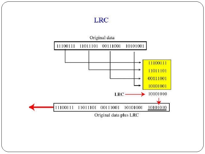
Longitudinal Redundancy Check (LRC) �A block of bits is organized in a table (rows and columns). �Then calculate parity bit for each column and create a new row, which are parity bits for the whole block.
Performance: � LRC of n bits can easily detect a burst error of n bits. � A burst error of more than n bits is also detected by LRC with a high probability. Example: if 2 bits in one data unit are damaged, and 2 bits in exactly the same position in another data unit are damaged, the LRC checker will not detect the error.
Cyclic Redundancy Check (CRC) � Most powerful redundancy checking technique. � Unlike VRC and LRC, which are based on addition-, CRC is based on binary division. � A CRC or CRC remainder is appended to the end of a data unit so that the resulting data unit becomes exactly divisible by a second, predetermined binary number(divisor). � At destination, incoming data unit is divided by the same number. � If no remainder- then data unit is intact. � If there is a remainder- means data unit is damaged. � Note: a CRC must have exactly one bit less than divisor.
CRC
1) A string of “n” 0 s is appended to the data unit. The 2) 3) 4) 5) number of n is one less than the number of bits in the predetermined divisor (which is n+1 bits). The new data unit is divided by the divisor using a process called binary division. The remainder is the CRC of n bits replaces the appended 0 s at the end of data unit. CRC may consist of all 0 s. The data unit arrives at receiver- data first , followed by CRC. The receiver treats whole string as a unit and divides by the same divisor. If remainder is zero - data unit is allowed to pass, else it is rejected.
Binary Division • Each bit of the divisor is subtracted from the corresponding bit of the dividend without disturbing the next higher bit.
Polynomials � The CRC generator(the divisor) is most often represented not as a string of 1 s and 0 s, but as an algebraic polynomial. � A polynomial selected should have following properties: 1) It should not be divisible by x : it guarantees that all the burst errors of a length equal to the degree of polynomial are detected. 2) It should be divisible by x+1 : it guarantees that all burst errors affecting an odd number of bits are detected.
Polynomial and Divisor
Standard Polynomials The numbers 12, 16, and 32 refers to the size of CRC remainder. The CRC divisors are 13, 17, and 33 bits, respectively.
Performance: � CRC can detect all burst errors that affect an odd number of bits. � CRC can detect all burst errors of length less than or equal to the degree of polynomial. � CRC can detect with a very high probability – burst errors of length greater than the degree of the polynomial.
Checksum �It is also based on the concept of redundancy.
Checksum Generator � Data segment is subdivided into equal segments of n units. � These segments are added together using 1’s complement arithmetic in such a way that total is also nbits long. � The total sum is then complemented and appended to the end of original data unit, called checksum field. � Means if the sum of the data segment is T, checksum is – T. � Extended data unit is transmitted across the network.
Checksum
Checksum Checker � The receiver subdivides the data unit into segments-each of n bits, and adds all segments together. � Then it complements the result. � If total found is zero - data unit is intact. � If total is not zero – means data unit contains error.
Data Unit and Checksum
AT SENDER: 1 0 0 0 1 Word 1 1 0 1 1 1 0 0 0 Word 2 ------------------1 0 0 0 1 Sum using one’s complement arithmetic 1 Remove carry and add it back ------------------0 1 0 sum 1 0 1 checksum The pattern sent is <------- word 1 word 2 checksum AT RECEIVER: 1 0 0 0 1 Word 1 1 0 1 1 1 0 0 0 Word 2 1 0 1 Checksum ------------------1 1 1 1 0 Sum using one’s complement arithmetic 1 Remove carry and add it back ------------------1 1 1 1 sum 0 0 0 0 complement //means the pattern is OK
Performance: � Detects all errors involving an odd number of bits. � Detects most errors involving even number of bits. � If one or more bits of a segment are damaged, and corresponding bits of opposite value in a second segment are also damaged, the sum of these columns will not change and the receiver will not detect a problem. � In LRC, two 0 s could both change to 1 s without altering the parity because carries were discarded. � Checksum retains all carries, so although two 0 s becoming 1 s would not alter the value of their own column, they would change the value of next higher column.
Checksum example 10001001 11110000 00111100 10100001 Input Word 2 Input Word 3 Input Word 4 1 0 0 0 1 W 1 1 1 0 0 W 2 ----------------------------------1 0 1 1 0 0 1 Sum 1 Carry ----------------------------------0 1 1 0 1’s Comp sum W 1, W 2 0 0 1 1 0 0 W 3 ----------------------------------1 0 1’s Comp sum W 1, W 2, W 3 1 0 0 0 0 1 W 4 ----------------------------------1 0 1 1 0 0 1 Sum 1 Carry ----------------------------------0 1 1 0 1’s Comp sum W 1, W 2, W 3, W 4 1 0 0 1 Complement = Checksum
Error correction � Error-correcting codes are more sophisticated than error detection codes, and require more redundancy bits. � The number of bits required to correct a burst error is so high that in most cases , it is inefficient to do so. � Therefore, most error-correction is limited to one- , two- , or three bits.
Single-bit error correction: � First step in error correction is locating invalid bit position. � Suppose data is composed of 7 bit ASCII code. To locate one of the 7 positions , 3 extra bits are sufficient. � But if the error occurs in these additional bits, so to cover all possibilities(7 bits of data+3 redundant bits), we need additional bits.
Redundancy bits: � ‘r’ must be able to indicate ‘m+r+1’ different states. � One state means no error , and ‘m+r’ states indicates the location of error in m+r different positions.
Redundancy bits: � R bits can indicate 2 r different states. � Therefore 2 r >=m+r+1 � Example: if value of m=7, then r=4.
Hamming code � Positioning the redundancy bits: use the positions that are powers of 2. (r 1, r 2, r 4, r 8). � Each ‘r’ bit is the VRC bit (parity bit) for one combination of data bits.
� Each data bit may be included in more than one VRC calculation. R 1: R 2: R 4: R 8: bits 1, 3, 5, 7, 9, 11 bits 2, 3, 6, 7, 10, 11 bits 4, 5, 6, 7 bits 8, 9, 10, 11 � The ‘r 1’ bit is calculated using all the bit positions whose binary representation includes a 1 in the rightmost position. � The ‘r 2’ bit is calculated using all bit positions with a 1 in the second position, and so on.
� The parity for each combination is the value of the corresponding ‘r’ bit. � The final 11 -bit code is sent through transmission line.
� Suppose data contains error.
Error Detection Reassemble the new parity values into a binary number in the order of ‘r’ position. (r 8, r 4, r 2, r 1). Error Correction. Reverse the bit value and correct the error.