IEEE SCV Communications Society Lecture CMOS for Ultra

- Slides: 43
IEEE SCV Communications Society Lecture CMOS for Ultra Wideband 60 GHz Communications Bob Brodersen Dept. of EECS Univ. of Calif. Berkeley http: //bwrc. eecs. berkeley. edu Berkeley Wireless Research Center
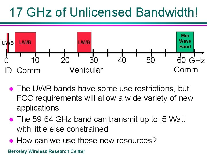
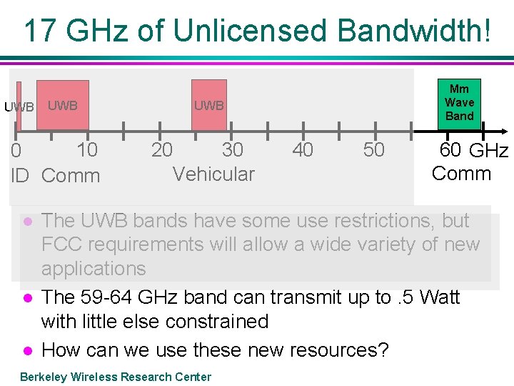
17 GHz of Unlicensed Bandwidth! UWB 10 0 ID Comm l l l Mm Wave Band UWB 20 30 Vehicular 40 50 60 GHz Comm The UWB bands have some use restrictions, but FCC requirements will allow a wide variety of new applications The 59 -64 GHz band can transmit up to. 5 Watt with little else constrained How can we use these new resources? Berkeley Wireless Research Center
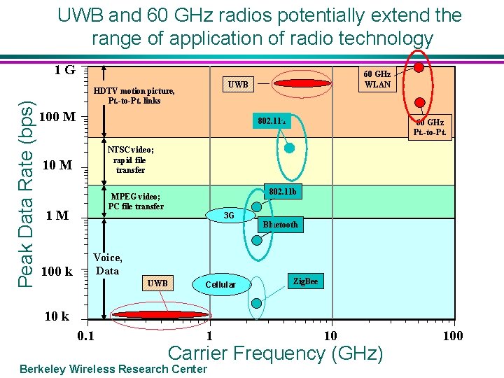
UWB and 60 GHz radios potentially extend the range of application of radio technology Peak Data Rate (bps) 1 G UWB HDTV motion picture, Pt. -to-Pt. links 100 M 802. 11 a 60 GHz Pt. -to-Pt. NTSC video; rapid file transfer 10 M 802. 11 b MPEG video; PC file transfer 1 M 100 k 60 GHz WLAN 3 G Bluetooth Voice, Data UWB Cellular Zig. Bee 10 k 0. 1 1 10 Carrier Frequency (GHz) Berkeley Wireless Research Center 100
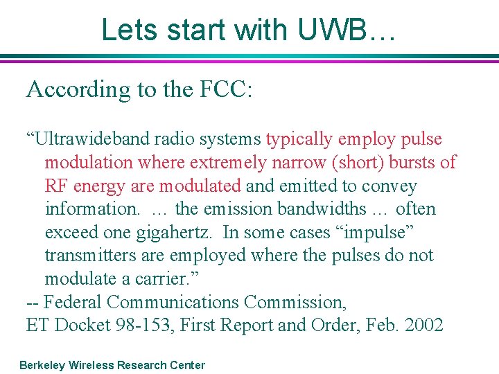
Lets start with UWB… According to the FCC: “Ultrawideband radio systems typically employ pulse modulation where extremely narrow (short) bursts of RF energy are modulated and emitted to convey information. … the emission bandwidths … often exceed one gigahertz. In some cases “impulse” transmitters are employed where the pulses do not modulate a carrier. ” -- Federal Communications Commission, ET Docket 98 -153, First Report and Order, Feb. 2002 Berkeley Wireless Research Center
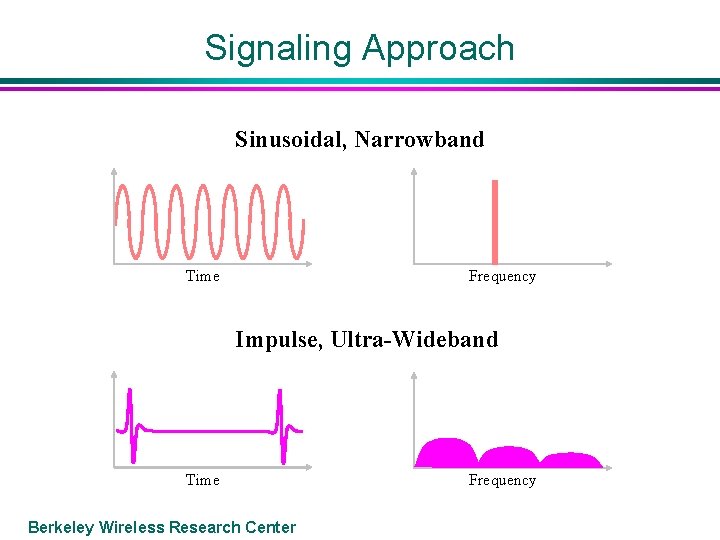
Signaling Approach Sinusoidal, Narrowband Frequency Time Impulse, Ultra-Wideband Time Berkeley Wireless Research Center Frequency
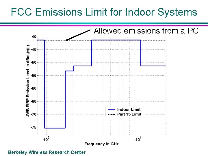
FCC Emissions Limit for Indoor Systems /MHz Allowed emissions from a PC Berkeley Wireless Research Center
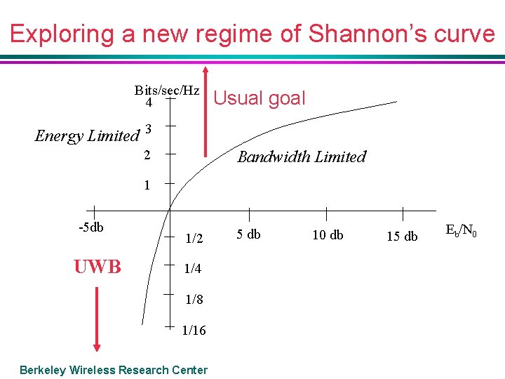
Exploring a new regime of Shannon’s curve Bits/sec/Hz 4 Usual goal Energy Limited 3 2 Bandwidth Limited 1 -5 db UWB 1/2 1/4 1/8 1/16 Berkeley Wireless Research Center 5 db 10 db 15 db Eb/N 0
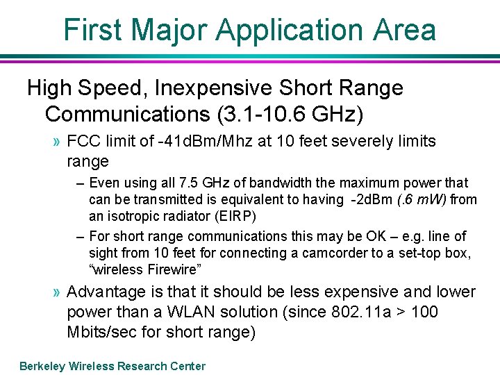
First Major Application Area High Speed, Inexpensive Short Range Communications (3. 1 -10. 6 GHz) » FCC limit of -41 d. Bm/Mhz at 10 feet severely limits range – Even using all 7. 5 GHz of bandwidth the maximum power that can be transmitted is equivalent to having -2 d. Bm (. 6 m. W) from an isotropic radiator (EIRP) – For short range communications this may be OK – e. g. line of sight from 10 feet for connecting a camcorder to a set-top box, “wireless Firewire” » Advantage is that it should be less expensive and lower power than a WLAN solution (since 802. 11 a > 100 Mbits/sec for short range) Berkeley Wireless Research Center
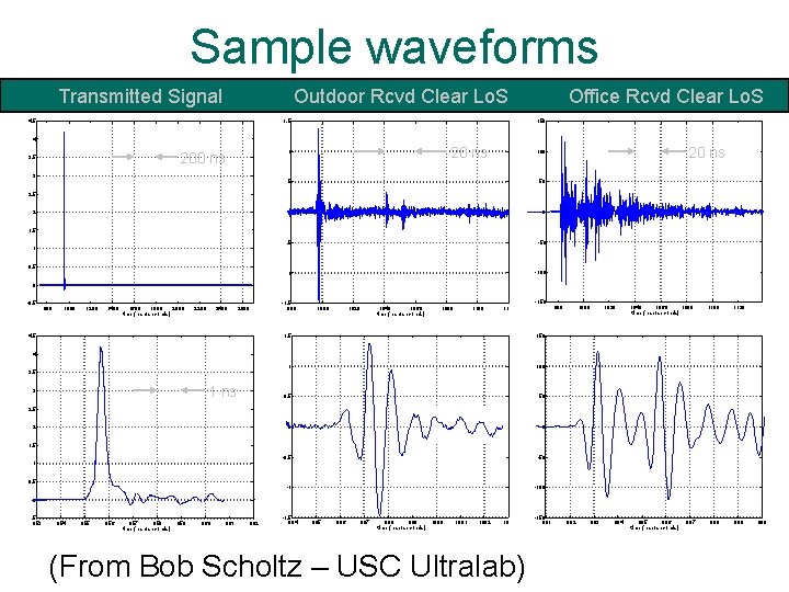
Sample waveforms Transmitted Signal Outdoor Rcvd Clear Lo. S 4. 5 Office Rcvd Clear Lo. S 150 1. 5 4 20 ns 1 200 ns 3. 5 3 20 ns 100 0. 5 50 0 0 -0. 5 -50 -1 -100 2. 5 2 1. 5 1 0. 5 0 -0. 5 800 1000 1200 1400 1600 1800 2000 time (nanoseconds) 2200 2400 2600 4. 5 -1. 5 980 1000 1020 1040 1060 time (nanoseconds) 1080 1100 1120 -150 1. 5 150 1 100 0. 5 50 0 0 -0. 5 -50 -1 -100 980 1000 1020 1040 1060 1080 time (nanoseconds) 1100 1120 988 989 4 3. 5 1 ns 3 2. 5 2 1. 5 1 0. 5 0 -0. 5 953 954 955 956 957 958 time (nanoseconds) 959 960 961 962 -1. 5 994 995 996 997 998 999 time (nanoseconds) 1000 1001 1002 1003 (From Bob Scholtz – USC Ultralab) Berkeley Wireless Research Center -150 981 982 983 984 985 986 time (nanoseconds) 987 990
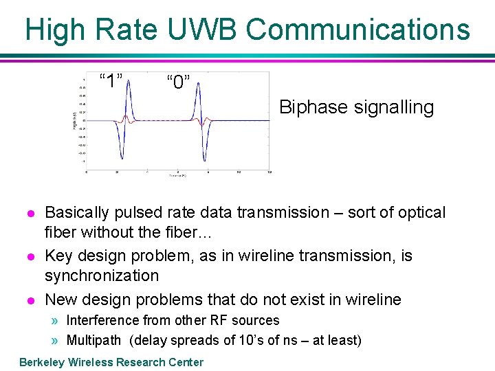
High Rate UWB Communications “ 1” “ 0” Biphase signalling l l l Basically pulsed rate data transmission – sort of optical fiber without the fiber… Key design problem, as in wireline transmission, is synchronization New design problems that do not exist in wireline » Interference from other RF sources » Multipath (delay spreads of 10’s of ns – at least) Berkeley Wireless Research Center
High Data Rate UWB l To Minimize Interference » Break 7. 5 GHz into smaller bands (> 500 MHz) and transmit in clear bands » Filter out bands that are likely to have use (e. g. 5 GHz wireless LAN bands) » Directional antennas l Multipath » Equalizers (as used in SERDES), but much longer delay compensation – digital? » Directional antennas Berkeley Wireless Research Center
Second Major Application Area Low Data Rate, Short Range Communications with Locationing (< 960 MHz) » Round trip time for pulse provides range information – multiple range estimates provides location » Used for asset tracking – a sophisticated RFID tag that provides location » Can be used to track people (children, firemen in buildings) » Sensor networks Berkeley Wireless Research Center
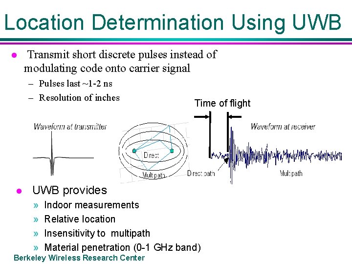
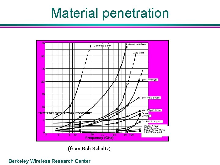
Location Determination Using UWB l Transmit short discrete pulses instead of modulating code onto carrier signal – Pulses last ~1 -2 ns – Resolution of inches l Time of flight UWB provides » » Indoor measurements Relative location Insensitivity to multipath Material penetration (0 -1 GHz band) Berkeley Wireless Research Center
Material penetration (from Bob Scholtz) Berkeley Wireless Research Center
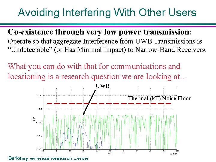
Avoiding Interfering With Other Users Co-existence through very low power transmission: Operate so that aggregate Interference from UWB Transmissions is “Undetectable” (or Has Minimal Impact) to Narrow-Band Receivers. What you can do with that for communications and locationing is a research question we are looking at… UWB Thermal (k. T) Noise Floor Berkeley Wireless Research Center
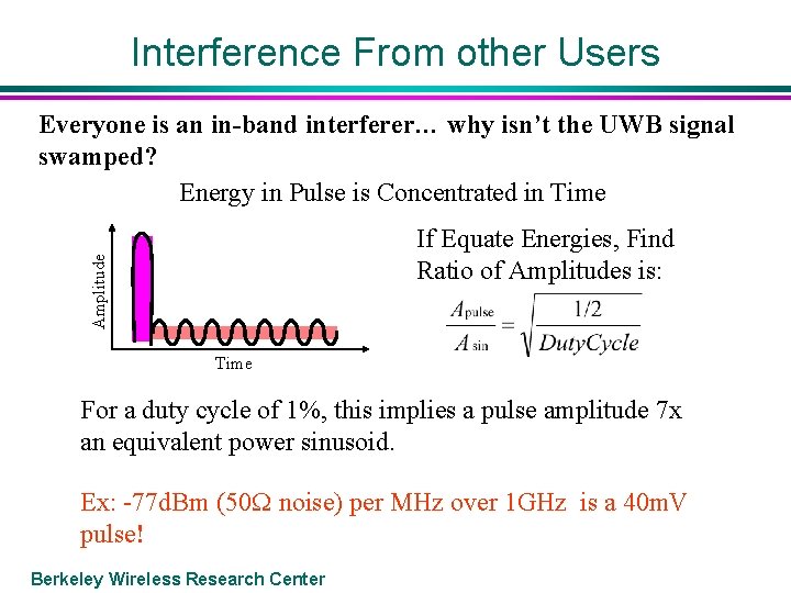
Interference From other Users Everyone is an in-band interferer… why isn’t the UWB signal swamped? Energy in Pulse is Concentrated in Time Amplitude If Equate Energies, Find Ratio of Amplitudes is: Time For a duty cycle of 1%, this implies a pulse amplitude 7 x an equivalent power sinusoid. Ex: -77 d. Bm (50 W noise) per MHz over 1 GHz is a 40 m. V pulse! Berkeley Wireless Research Center
BWRC: UWB Transceiver Chip A single chip CMOS UWB transceiver at power levels of 1 m. W/MHz for locationing and tracking applications » Flexible design for a wide range of data rates to investigate UWB transmission characteristics » For low rate applications, transmission at minimum possible signal level » Develop limits of locationing accuracy Being Implemented by Ph. D students Ian O’Donnell, Mike Chen, Stanley Wang Berkeley Wireless Research Center
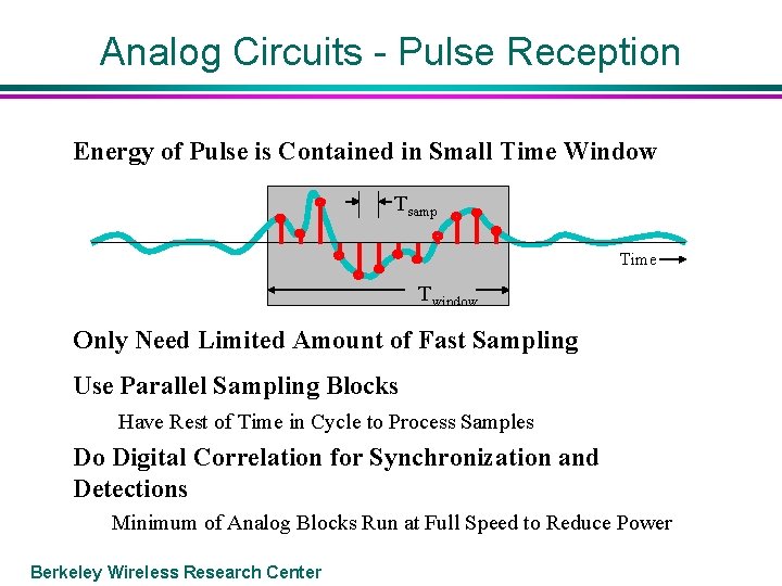
Analog Circuits - Pulse Reception Energy of Pulse is Contained in Small Time Window Tsamp Time Twindow Only Need Limited Amount of Fast Sampling Use Parallel Sampling Blocks Have Rest of Time in Cycle to Process Samples Do Digital Correlation for Synchronization and Detections Minimum of Analog Blocks Run at Full Speed to Reduce Power Berkeley Wireless Research Center
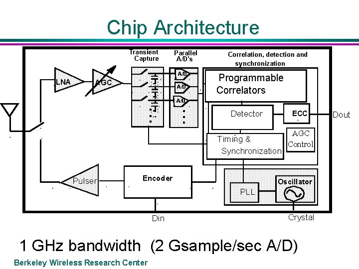
Chip Architecture Transient Capture Parallel A/D’s A/D LNA AGC A/D . . . Correlation, detection and synchronization Programmable Correlators A/D . . . Detector ECC AGC Timing & Control Synchronization Pulser Encoder Oscillator PLL Din Crystal 1 GHz bandwidth (2 Gsample/sec A/D) Berkeley Wireless Research Center Dout
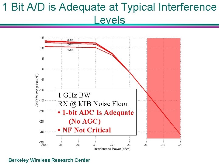
1 Bit A/D is Adequate at Typical Interference Levels 1 GHz BW RX @ k. TB Noise Floor • 1 -bit ADC Is Adequate (No AGC) • NF Not Critical Berkeley Wireless Research Center
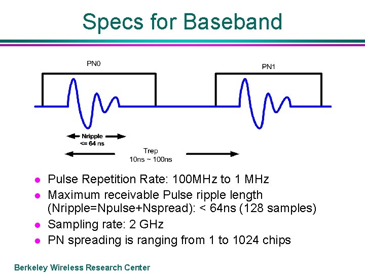
Specs for Baseband l l Pulse Repetition Rate: 100 MHz to 1 MHz Maximum receivable Pulse ripple length (Nripple=Npulse+Nspread): < 64 ns (128 samples) Sampling rate: 2 GHz PN spreading is ranging from 1 to 1024 chips Berkeley Wireless Research Center
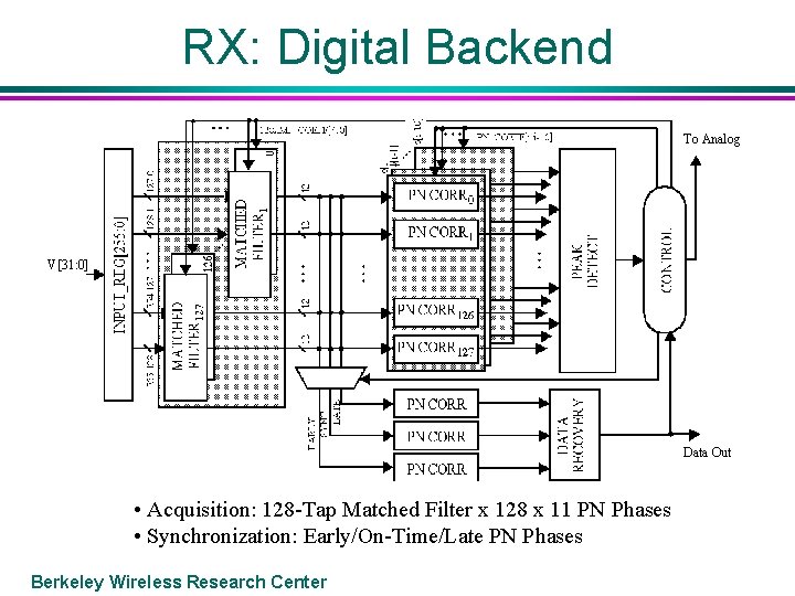
RX: Digital Backend To Analog V[31: 0] Data Out • Acquisition: 128 -Tap Matched Filter x 128 x 11 PN Phases • Synchronization: Early/On-Time/Late PN Phases Berkeley Wireless Research Center
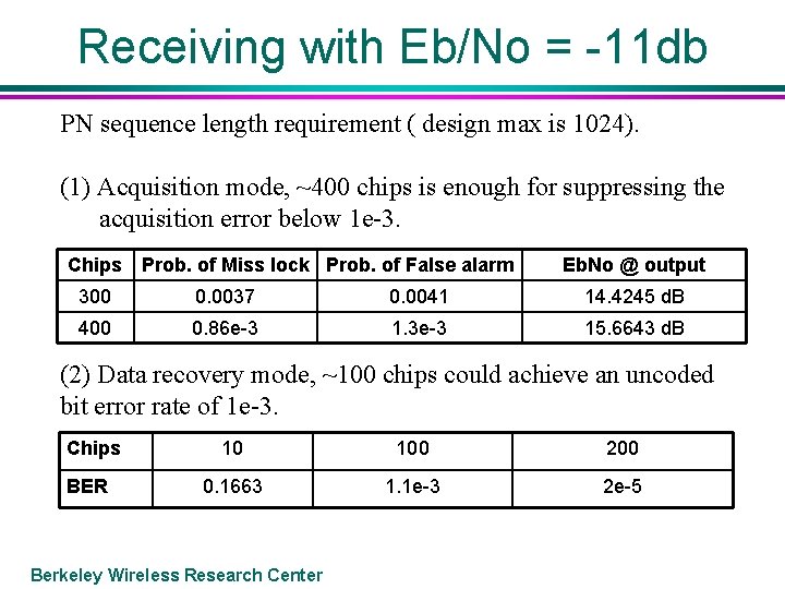
Receiving with Eb/No = -11 db PN sequence length requirement ( design max is 1024). (1) Acquisition mode, ~400 chips is enough for suppressing the acquisition error below 1 e-3. Chips Prob. of Miss lock Prob. of False alarm Eb. No @ output 300 0. 0037 0. 0041 14. 4245 d. B 400 0. 86 e-3 1. 3 e-3 15. 6643 d. B (2) Data recovery mode, ~100 chips could achieve an uncoded bit error rate of 1 e-3. Chips BER 10 100 200 0. 1663 1. 1 e-3 2 e-5 Berkeley Wireless Research Center
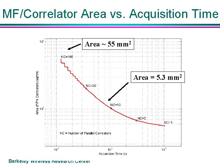
MF/Correlator Area vs. Acquisition Time Area ~ 55 mm 2 Area = 5. 3 mm 2 Berkeley Wireless Research Center
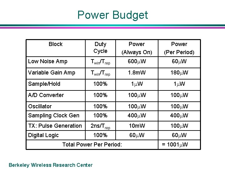
Power Budget Block Duty Cycle Power (Always On) Power (Per Period) Low Noise Amp Twin/Trep 600 W 60 W Variable Gain Amp Twin/Trep 1. 8 m. W 180 W Sample/Hold 100% 1 W A/D Converter 100% 100 W Oscillator 100% 100 W Sampling Clock Gen 100% 400 W TX: Pulse Generation 2 ns/Trep 10 m. W 100% 60 W Digital Logic Total Power Period: Berkeley Wireless Research Center = 1001 W
Status Chip tape out by summer in. 13 micron technology l Stay tuned at l http: //bwrc. eecs. berkeley. edu/Research/UWB/ Berkeley Wireless Research Center
17 GHz of Unlicensed Bandwidth! UWB 10 0 ID Comm l l l Mm Wave Band UWB 20 30 Vehicular 40 50 60 GHz Comm The UWB bands have some use restrictions, but FCC requirements will allow a wide variety of new applications The 59 -64 GHz band can transmit up to. 5 Watt with little else constrained How can we use these new resources? Berkeley Wireless Research Center
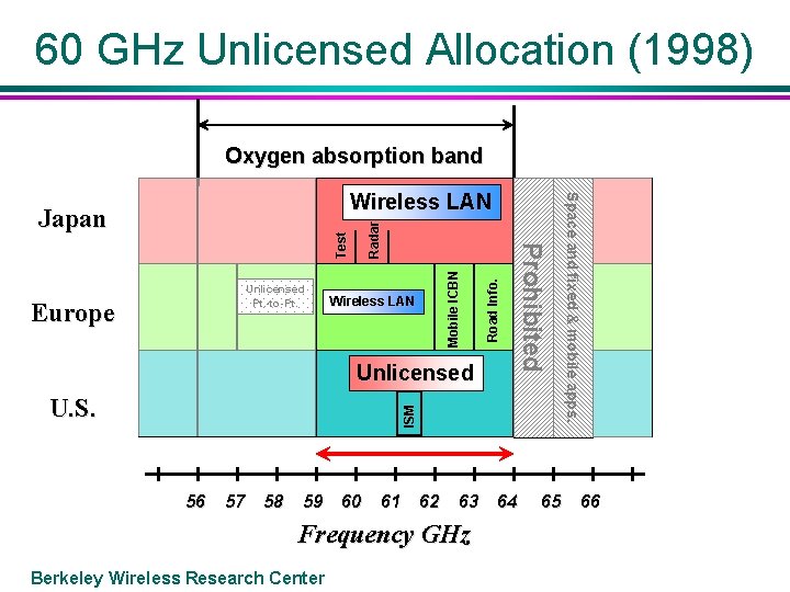
60 GHz Unlicensed Allocation (1998) Oxygen absorption band Radar Wireless LAN Unlicensed ISM U. S. Road Info. Europe Mobile ICBN Unlicensed Pt. -to-Pt. P r o h i b i te d Test Japan 56 57 58 59 60 61 62 63 Frequency GHz Berkeley Wireless Research Center 64 65 S p a c e a n d fi x e d & m o b i l e a p p s. Wireless LAN 66
Exploiting the Unlicensed 60 GHz Band 5 GHz of unlicensed and pretty much unregulated bandwidth is available l Requires l » New approaches for design of CMOS integrated circuits (distributed, transmission line based) » New system architectures Berkeley Wireless Research Center
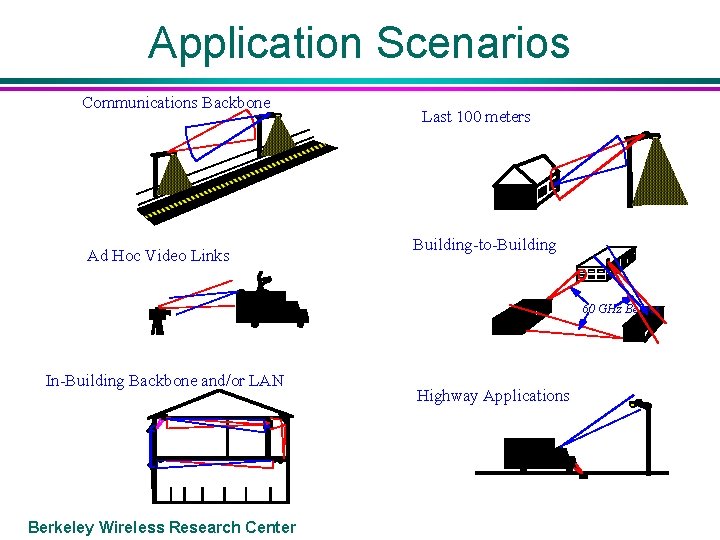
Application Scenarios Communications Backbone Last 100 meters Building-to-Building Ad Hoc Video Links XBC In-Building Backbone and/or LAN Berkeley Wireless Research Center 60 GHz Beams Highway Applications
Why Isn’t 60 GHz in Widespread Use? Oxygen absorbs RF energy at 60 GHz l The technology to process signals at 60 GHz is very expensive l The signal radiated is attenuated by the small antenna size – i. e. the power transmitted at 60 Ghz from a quarter wave dipole is 20 d. B less than at 5 GHz. l Berkeley Wireless Research Center
Oxygen attenuation The oxygen attenuation is about 15 d. B/km, so for most of the applications this is not a significant component of loss For long range outdoor links, worst case rain conditions are actually a bigger issue Berkeley Wireless Research Center
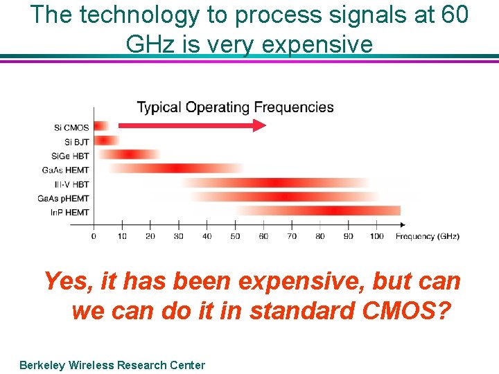
The technology to process signals at 60 GHz is very expensive Yes, it has been expensive, but can we can do it in standard CMOS? Berkeley Wireless Research Center
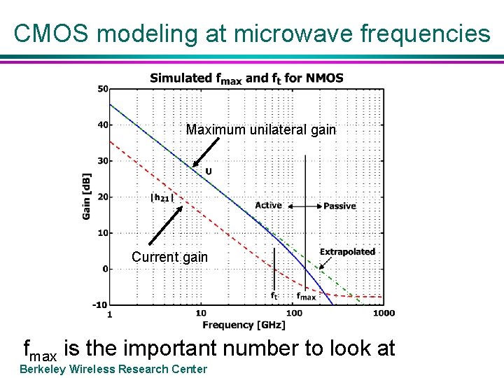
CMOS modeling at microwave frequencies Maximum unilateral gain Current gain fmax is the important number to look at Berkeley Wireless Research Center
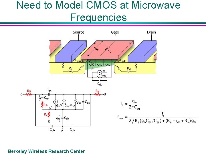
Need to Model CMOS at Microwave Frequencies Berkeley Wireless Research Center
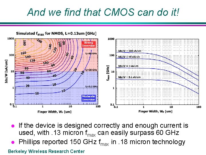
And we find that CMOS can do it! l l If the device is designed correctly and enough current is used, with. 13 micron fmax can easily surpass 60 GHz Phillips reported 150 GHz fmax in. 18 micron technology Berkeley Wireless Research Center
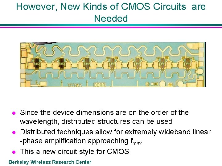
However, New Kinds of CMOS Circuits are Needed l l l Since the device dimensions are on the order of the wavelength, distributed structures can be used Distributed techniques allow for extremely wideband linear -phase amplification approaching fmax This a new circuit style for CMOS Berkeley Wireless Research Center
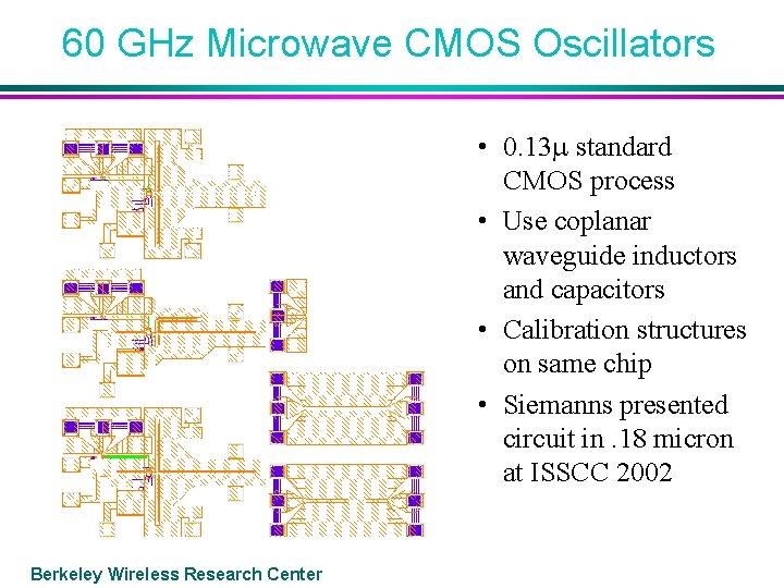
60 GHz Microwave CMOS Oscillators • 0. 13 standard CMOS process • Use coplanar waveguide inductors and capacitors • Calibration structures on same chip • Siemanns presented circuit in. 18 micron at ISSCC 2002 Berkeley Wireless Research Center
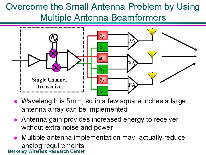
Overcome the Small Antenna Problem by Using Multiple Antenna Beamformers a 0 b 0 a 1 b 1 Single Channel Transceiver l l l a 2 b 2 PA PA PA Wavelength is 5 mm, so in a few square inches a large antenna array can be implemented Antenna gain provides increased energy to receiver without extra noise and power Multiple antenna implementation may actually reduce analog requirements Berkeley Wireless Research Center
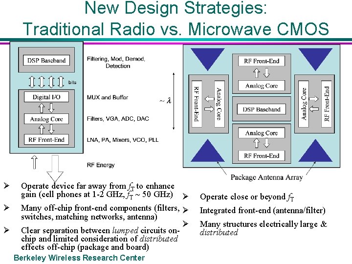
New Design Strategies: Traditional Radio vs. Microwave CMOS Ø Ø Ø Operate device far away from f. T to enhance gain (cell phones at 1 -2 GHz, f. T ~ 50 GHz) Ø Many off-chip front-end components (filters, Ø switches, matching networks, antenna) Ø Clear separation between lumped circuits onchip and limited consideration of distributed effects off-chip (package and board) Berkeley Wireless Research Center Operate close or beyond f. T Integrated front-end (antenna/filter) Many structures electrically large & distributed
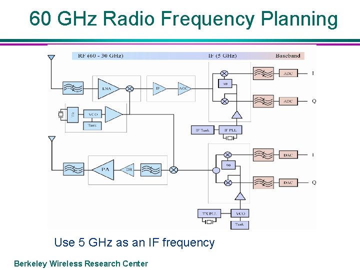
60 GHz Radio Frequency Planning Use 5 GHz as an IF frequency Berkeley Wireless Research Center
The open question… l What is the best way to use 5 GHz of bandwidth to implement a high datarate link? » Extremely inefficient modulation but at a very high rate? (say 2 GHz of bandwidth for 1 Gigabit/sec) – requires analog processing » Or use an efficient modulation, so lower bandwidth. e. g. OFDM – but needs digital processing and a fast A/D Berkeley Wireless Research Center
Conclusions UWB radios provide a new way to utilize the spectrum and there is a wide variety of unique applications of this technology However, it takes a completely new kind of radio design… l At the present state of technology CMOS is able to exploit the unlicensed 60 GHz band However, it will take a new design and modeling methodology… l There is 17 GHz of bandwidth ready to be used for those willing to try something new! Berkeley Wireless Research Center