Gravity Rush Explore and master gravity as you


.")


.")


 on Robot Design Stack: A V 5")


- Slides: 82
Gravity Rush Explore and master gravity as you race to the finish line!
Discover new hands-on builds and programming opportunities to further your understanding of a subject matter.
The Completed Look of the Build Completed VEX V 5 Clawbot The VEX V 5 Clawbot is an extension of the VEX V 5 Speedbot that can be programmed to move around and interact with objects.
Parts Needed: Part 1 Can be built with: VEX V 5 Classroom Starter Kit
Parts Needed: Part 2
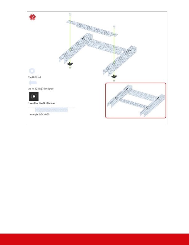
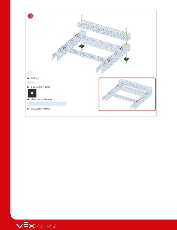
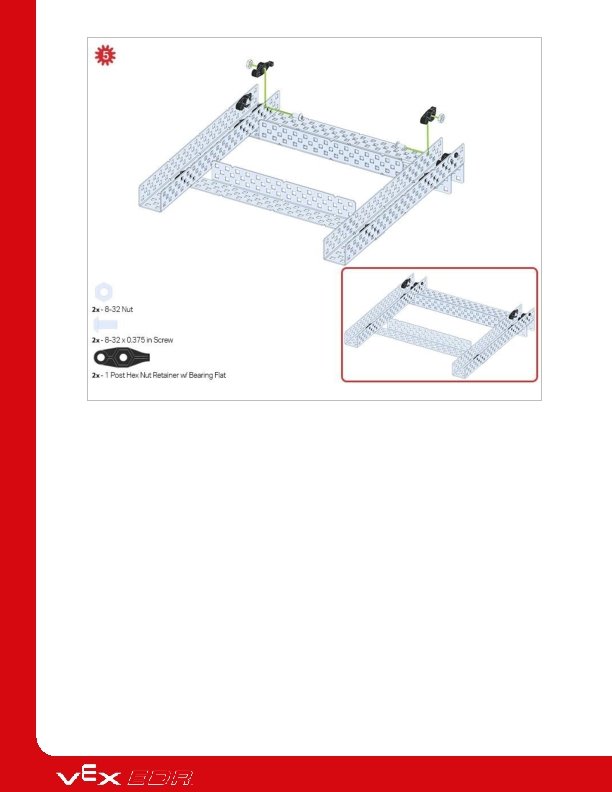
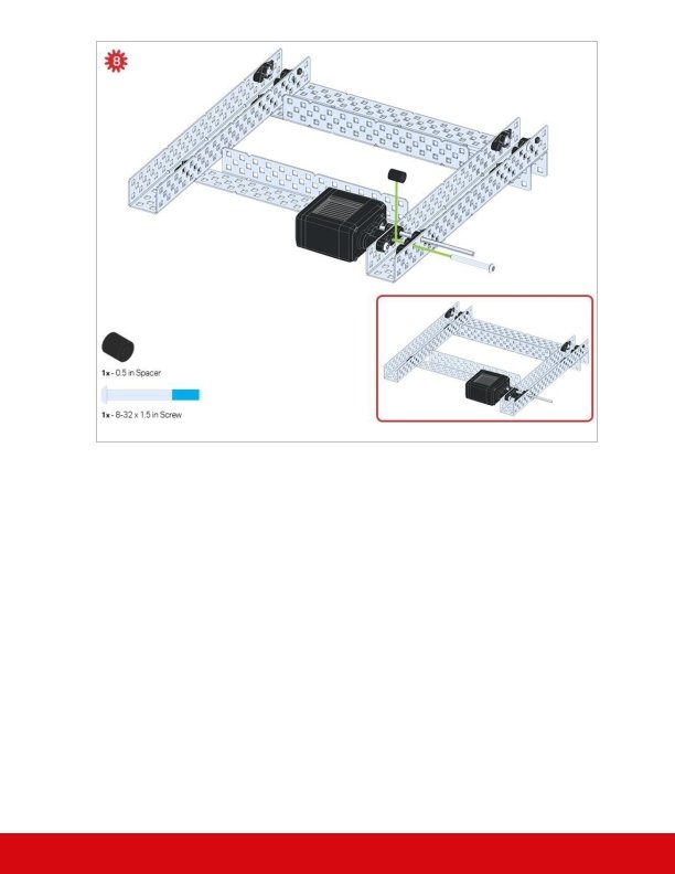
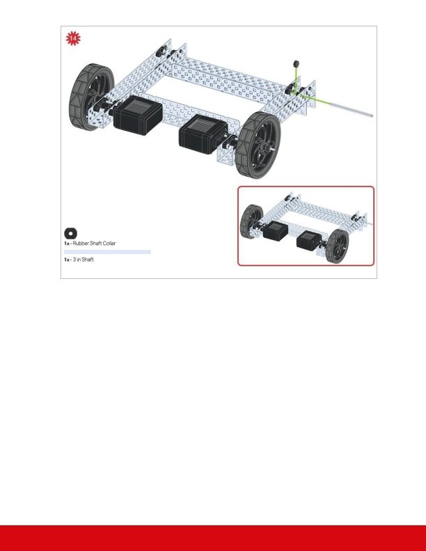
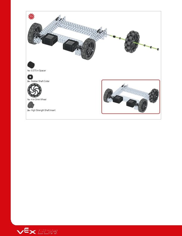
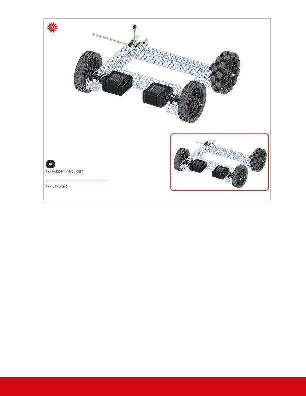
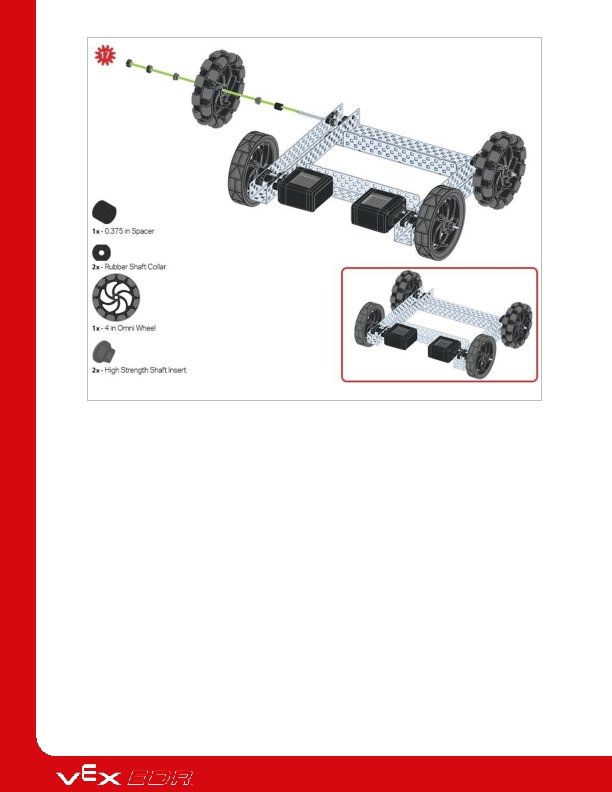
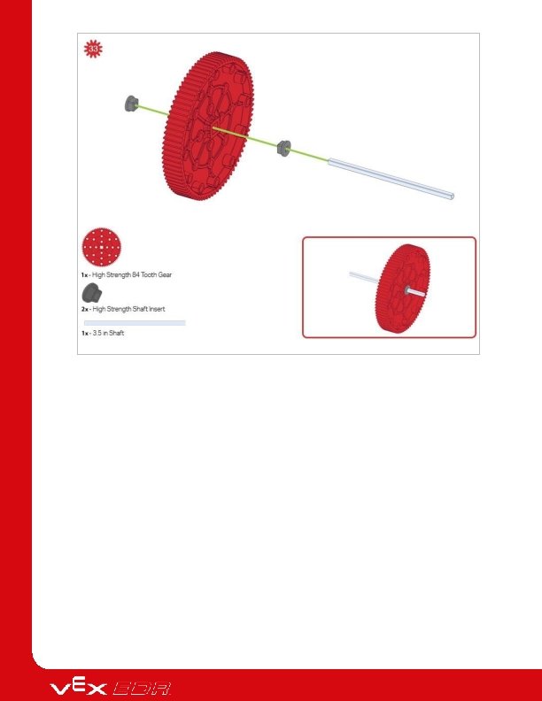
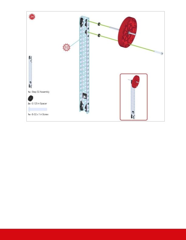
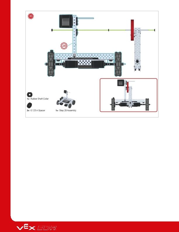
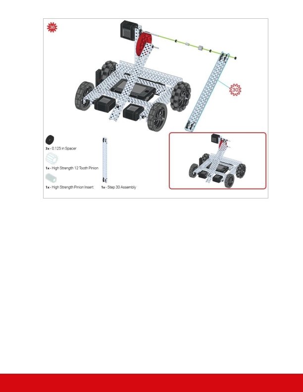
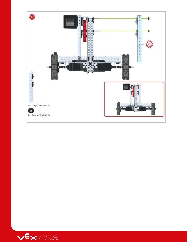
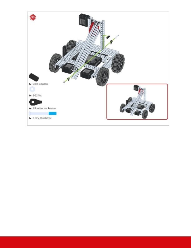
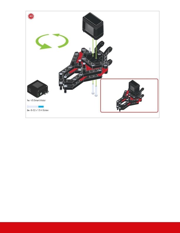
Build Instructions
The green icon indicates that the build needs to be flipped over (upside down).
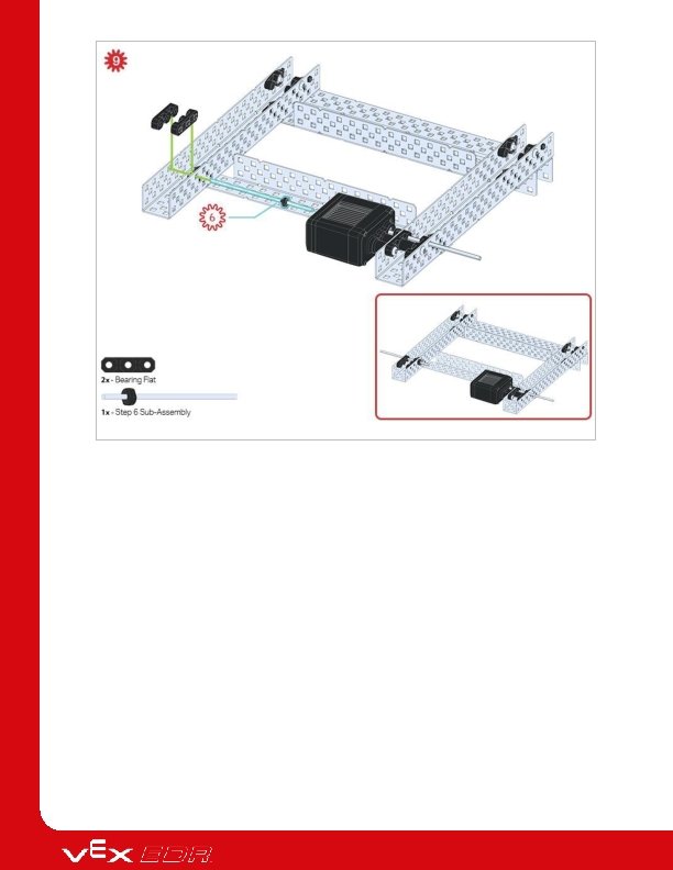
Only one of the two sub-assemblies made in this step is used right now. The other will be used later in step 9.
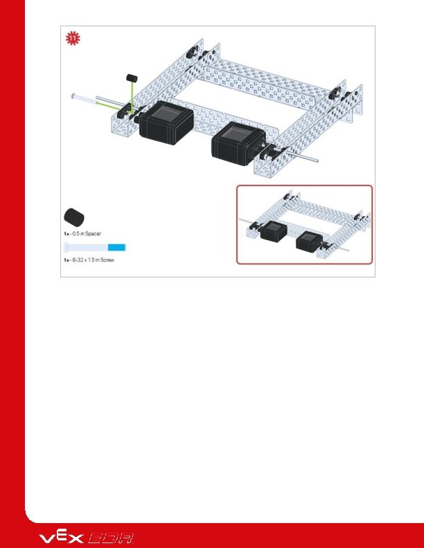
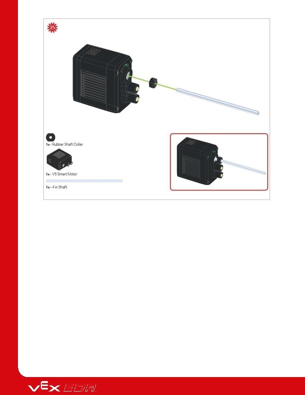
Make sure your Smart Motors are oriented in the correct direction (screw holes facing the outside of the build and the shaft hole towards the inside).
Make sure your Smart Motors are oriented in the correct direction (screw holes facing the outside of the build and the shaft hole towards the inside).
The green icon indicates that the build needs to be rotated (180 degrees).
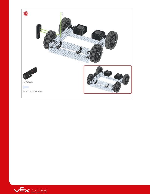
The blue call out shows what the orientation of the Robot Brain should be if the build were flipped right side up. Make sure the 3 wire ports on the Robot Brain are facing the V 5 Radio!
The green call outs indicate which port on the Robot Brain to plug each device into using their respective cable.
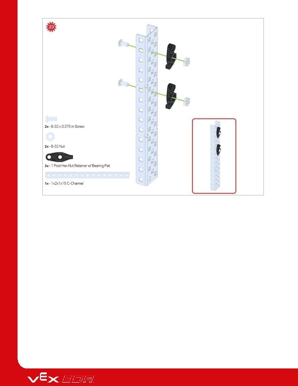
Be sure to make two assemblies in this step!
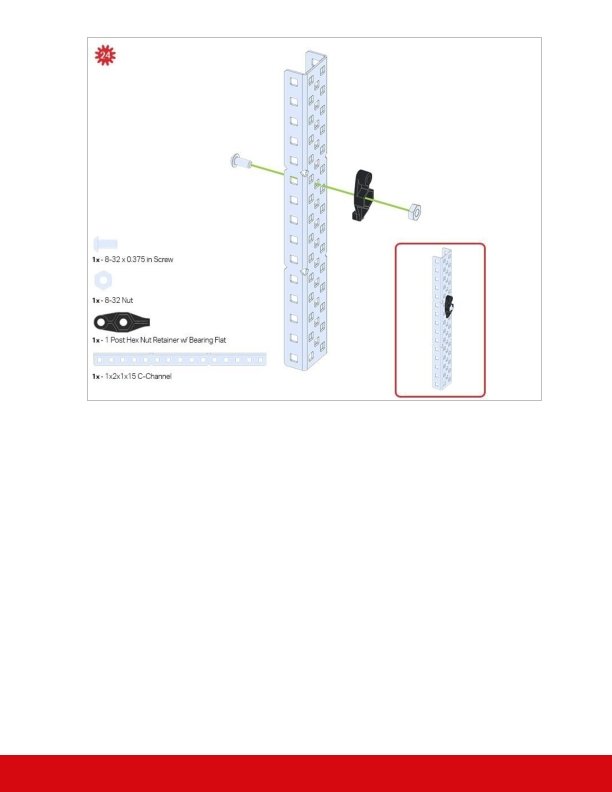
This step adds onto the two assemblies started in Step 29.
Make sure to add this to only one of the two sub-assemblies you just made.
Make sure the 12 - tooth gear is installed on the right side of the claw.
Make sure that the port on the Smart Motor is facing the right side of the robot when the claw is installed (the same side as the V 5 Radio).
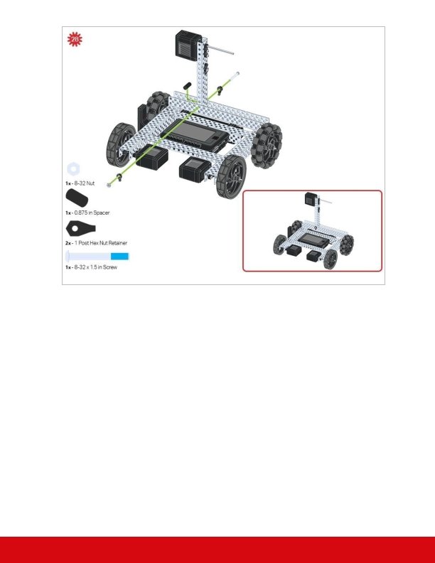
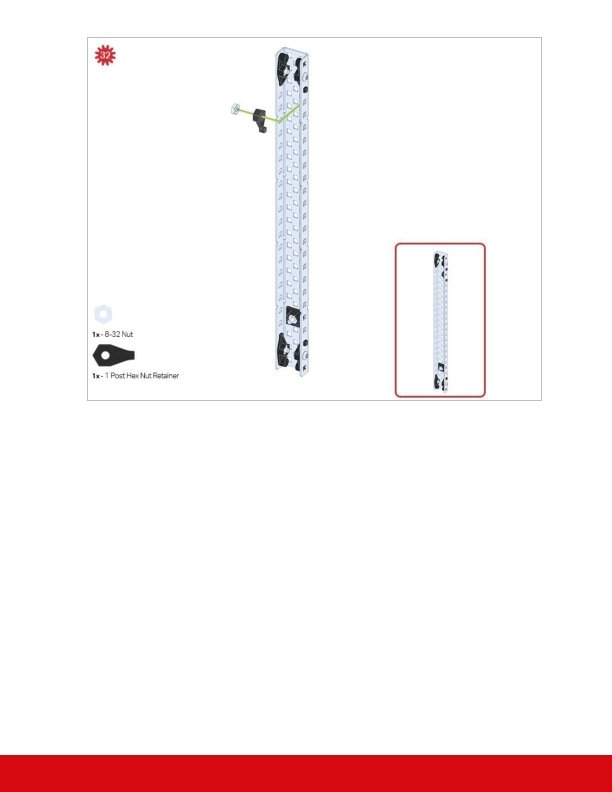
Build Instruction Tips Check the Appendix for information on how to use the new Hex Nut Retainers.
Exploration Now that you've finished the build, test what it does. Experiment with your build and then answer these questions in your engineering notebook. Describe how you would predict the robot’s behavior would change if the. V 5 Battery in Build step 21 was attached to the structural metal piece between the V 5 motors and the V 5 Brain instead of on the other side of the chassis. To aid with this question you can find the balance point for the robot by lifting the robot by the sides of the chassis with your index fingers and moving them forward and backwards until the robot balances on your fingers. Then picture how this would change if you moved the mass of the battery from one side to the other. How do you think gravity affects how this robot moves?
Test your build, observe how it functions, and fuel your logic and reasoning skills through imaginative, creative play.
Center of Gravity The Leaning Tower of Pisa Considering the Center of Gravity Every object has a center of gravity (Co. G). It is the location on the object where gravity pulling on any one side is balanced by gravity pulling on the opposite side. Another way to think of it is the average location of the weight of an object. If the Co. G stays above the base of the object (the part resting on the ground), the object will not fall over. The picture shows the famous Leaning Tower of Pisa. This tower is known for having a very visible tilt, about 4 degrees from being perfectly vertical (straight up and down). You can compare the arrow in the picture to the columns on the tower to see how tilted it is. Although the tower is so tilted, the Co. G is still above the base of the tower and so, the tower stays standing! If you further pushed the Leaning Tower in the above picture so it tilted more and more until the arrow passed the base of the tower, then it would fall over.
You can also think about a seesaw or a scale. The fulcrum, the point on the seesaw where the board rests, is directly under the seesaw's Co. G. If it weren't, the seesaw would fall to one side instead of teetering up and down.
Center of Gravity of Moving Objects A sign warning trucks to slow down or risk tipping over Balancing Gravity and Other Forces Consider the truck shown on the sign. Trucks that carry heavy loads are often taller than they are wide. Even so, if the truck's center of gravity (Co. G) stays above the wheels, the truck will stay upright. As the truck moves, changes in the slope or pitch of the road will affect the pull of gravity on the truck's Co. G. So will the truck's inertia. Inertia is the resistance an object has to change in its current state of motion or velocity. If the truck goes quickly around a curve, inertia will cause the mass of the truck to pull to one side. If these effects are strong enough, the wheels will no longer be under the Co. G, and the truck will topple over. Consider these factors, and how they affect a truck's Co. G: Does the truck's Co. G move as more weight is added to its cargo? If so, in which direction? How does the placement of cargo inside the truck affect the truck's Co. G? What happens if the cargo is able to slide or roll around inside the truck?
Exploring Center of Gravity with the Robot Amount Hardware/Software 2 VEX V 5 Classroom Starter Kits (with up-to-date firmware) 1 Roll of Tape 1 Materials to make a Small Ramp (wood, cardboard, binders, etc. ) 1 Meter Stick 1 Engineering Notebook 1. Clearing a Space 3 m x 1. 25 m racing track for the Claw Arm Challenge The first step in creating a course for your V 5 Clawbot is to clear a space on the floor approximately 3 meters (119 inches) by 1. 25 meters (49 inches). This will be the racing track
and allow two Clawbots to race side-by-side at the same time. Mark the space with tape or in some way so that the track is clearly marked with starting and finishing lines. 2. Building a Ramp VEX V 5 Clawbot going up a ramp The next step is to build a ramp that is as wide as the course (approx. 1. 25 meters or 49 inches). The ramp could be constructed using wood, cardboard, or anything available that is strong enough to hold the weight of the two V 5 Clawbots. The ramp should have two slopes, first upward and then downward, and should be sloped gradually so that there aren't gaps at either end of it.
3. Positioning the Ramp 3 m x 1. 25 m racing track with ramp Move the ramp to the second half of the course. The ramp should be at least 1. 5 meters (59 inches) from the starting line. Make sure the ramp is positioned so that its sides are precisely parallel to the sides of the track. In other words, make sure that the ramp is not crooked so that the V 5 Clawbot's front wheels can reach the ramp at exactly the same time.
4. Preparing the Robot V 5 Clawbot Power on the V 5 Robot Brain, make sure it is paired with the V 5 Controller, and run the Drive program on the V 5 Robot Brain so that you’re able to wirelessly drive your robot with the V 5 Controller.
5. Running with a Resting Arm V 5 Clawbot travelling the course with its arm all the way down The V 5 Clawbots should have their arms all the way down in the starting or resting position. 6. Running with an Angled Arm V 5 Clawbot travelling the course with its arm angled out During the second round, the new pairs will race their Clawbots again head-to-head.
In this round, each Clawbot's arm must be raised at least 25. 5 centimeters (approx. 10 inches) above its starting position. 7. Running with a Near-vertical Arm V 5 Clawbot travelling the course with its arm raised up During the third round, the V 5 Clawbots' arms must be raised 38 centimeters (approx. 15 inches) above its starting position. If you have just two teams, the team who wins Round 3's matchup is the winner of the challenge.
Become a 21 st century problem solver by applying the core skills and concepts you learned to other problems.
Testing, Collecting Data, & Informing Decisions Calculating the change in velocity and the change in time Where will you position the bottle as cargo? In the Claw Arm Challenge you will be transporting a bottle using the V 5 Clawbot. That would be easy but you need to race your robot with its claw arm raised to different heights. So in order to keep your robot from falling over, you will need to decide the best placement of the bottle. Test your assumptions and run some trials with your V 5 Clawbot. Start by investigating the following questions: Where is the V 5 Clawbot's center of gravity (Co. G)? Does its Co. G move when the claw arm is raised? If so, in which direction? How fast can the V 5 Clawbot accelerate and remaining stable while its arm is lowered? How fast can the V 5 Clawbot accelerate and remain stable while its arm is raised ? Does the position of the bottle affect the V 5 Clawbot's stability? Who should be the driver for each of the three rounds?
Logging data Data logging helps you collect the information you need to make a sound, justified decision. Using the example table below, record your results from at least 9 trial runs. Write the results of each trial in a new row. Fill out each column as follows: Driver: the name of the teammate who drove the robot Bottle Position: the location you placed the bottle on the robot Arm Height: the height the robot's arm was raised Acceleration: the measure of how quickly you accelerated the robot at the start o Acceleration = change in velocity / change in time Stayed Upright: yes or no After you have recorded each trial run, use the results to choose a position for the bottle that lets you accelerate quickly and remain stable. Example Data Log Driver Bottle Position Arm Height Acceleration Stayed Upright
Driver Bottle Position Arm Height Acceleration Stayed Upright
Effects of Center of Gravity (Co. G) on Robot Design Stack: A V 5 Competition Super Kit build Considering a Robot Design's Center of Gravity The robot shown above is called Stack. It is a build designed from the V 5 Competition Super Kit to compete in the 2019 -2020 VEX Robotics Competition game Tower Takeover.
Notice where Stack's battery and brain are positioned. Notice that its manipulators are motored and can be lowered and raised as needed. In order to design a competition-ready robot, the robot's design needs to be a stable one. That requires the team to consider where the robot's center of gravity is at all times. Raising a manipulator above a specific height should not risk having the robot tip - even at high speeds.
Is there a more efficient way to come to the same conclusion? Take what you’ve learned and try to improve it.
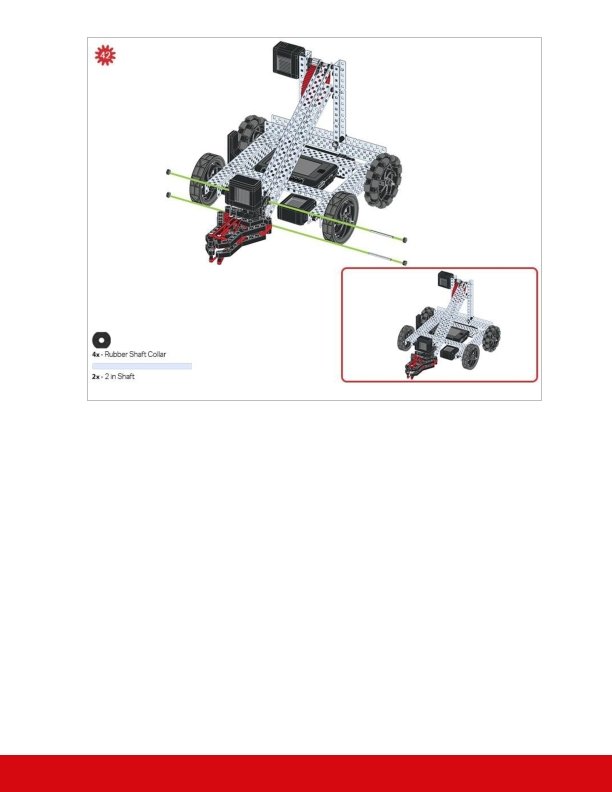
Prepare for the Claw Arm Challenge The race course with the ramp on the second half of the course Challenge Preparation Using the same course made while Exploring the Center of Gravity with the Robot, you will race a pair of V 5 Clawbots with their claw arm's raised to different heights during each round. Use what you've learned about a moving object's center of gravity and the data you've collected during your trials to properly position your bottle cargo for all three rounds. To prepare for this challenge you will need: A taped-off space on the floor approximately 3 meters (119 inches) long by 1. 25 meters (49 inches) wide. A ramp that is as wide as the course (approx. 1. 25 meters or 49 inches) at least 60 inches from the starting line. At least one sand-filled 500 m. L plastic bottle for each racing V 5 Clawbot. A place to record the winners of each round.
Review and Improve Your Plan for the Challenge Answer the following questions in your engineering notebook as your team reviews its plans for the challenge. Is the bottle in the best position it can be? If so, which position is that? How quickly should your V 5 Clawbot accelerate during the race? Which teammate is going to drive and control the V 5 Clawbot in each round? Review the data that your team collected while you tested your robot earlier. Is the position you chose for your bottle supported by the data during your trials? Is your chosen acceleration for the V 5 Clawbot supported by the data during your trials? Is the teammate driving the V 5 Clawbot in each round the same driver as in the trial for that round?
Claw Arm Challenge V 5 Clawbot going up a ramp with lines indicating the where the claw must be extended Claw Arm Challenge This is a challenge to see which V 5 Clawbot can make it over the ramp and to the finish line first with their V 5 Clawbot's arm extended out farther and farther each round. Challenge rules: All V 5 Clawbots will be controlled wirelessly and running the Drive program. All competing V 5 Clawbots must transport a full 500 m. L bottle from the starting line to the finishing line without allowing the bottle to touch the floor. Any V 5 Clawbot that tips over loses the match. During the first round, all V 5 Clawbots must have their claw arms down in the starting position. During the second round, all V 5 Clawbots must have their claw arms raised at least 25. 5 cm above its starting position. During the third round, all V 5 Clawbots must have their claw arms raised at least 38 cm above its starting position.
The same team member cannot control the V 5 Clawbot for two rounds in a row. So at least two different teammates will need to participate across the three rounds of the challenge. The winning and losing teams of each round then race in the next round. The winner of the Round 3 race of the fastest V 5 Clawbots wins the Claw Arm Challenge. Have Fun!
Understand the core concepts and how to apply them to different situations. This review process will fuel motivation to learn.
Review 1. True or False: A rigid object's center of gravity is unlikely to change, but a movable object's center of gravity is likely to change. o True o False 2. Which of the following are important when considering the stability of a moving object? o Its speed or acceleration o Its center of gravity o Any forces acting on it o All of these are important in determining the stability of a moving object. 3. Which of these forces is likely not important when considering the stability of a moving object? o Torque o Inertia o Gravity o All of these forces are important in determining the stability of a moving object. 4. True or False: A seesaw teeters up and down when the fulcrum is positioned at the board's center of gravity. o True o False 5. Which of these is not a strategy for improving your team's success? o Break larger problems down into smaller more manageable ones. o Practice each aspect of the challenge one phase at a time. o Allow team members to work independently without collaborating with others.
o Avoid distractions and stay on task to achieve a desired goal. 6. True or False: The V 5 Clawbot's center of gravity moved downward each time the claw arm was raised higher. o True o False 7. Which of the following describes the relationship between the position of the bottle, the height of the arm, and the appropriate acceleration? o The bottle could be held in the base of the V 5 Clawbot or in the claw and both let us use a fast acceleration without tipping over. o Holding the bottle in the claw with the arm high let us use a fast acceleration. o Holding the bottle in the base of the V 5 Clawbot (just above the Smart Motors) required us to use a slow acceleration no matter the height of the arm. o Holding the bottle in the base of the V 5 Clawbot (just above the Smart Motors) let us use a fast acceleration no matter the height of the arm. 8. True or False: The V 5 Clawbot would likely remain stable if the bottle was empty and in the claw with the arm high, even if we accelerated as fast as possible. o True o False 9. How did needing a different driver between rounds add to this challenge's difficulty? o It is difficult to explain to a teammate exactly how far to push the joystick to get the proper acceleration. o Each driver has her/his own habits for how they drive the V 5 Clawbot. o The driver's experience during the first round could not be used immediately in the second round. o All of these reasons made it more difficult to have a different driver in the second round.
Additional information, resources, and materials.
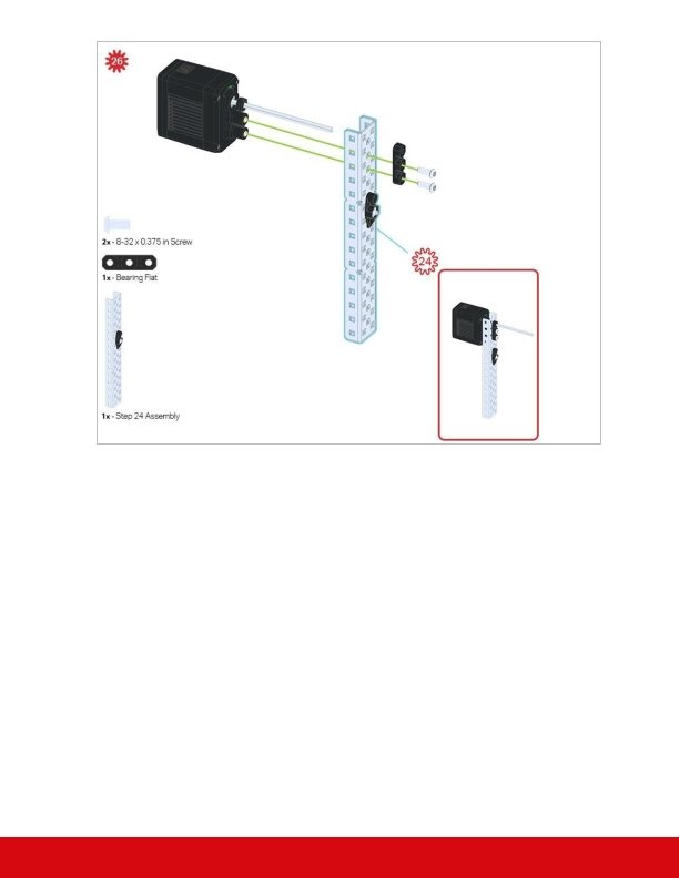
Using the 1 Post Hex Nut Retainer w/ Bearing Flat The 1 Post Hex Nut Retainer w/ Bearing Flat allows shafts to spin smoothly through holes in structural components. When mounted, it provides two points of contact on structural components for stability. One end of the retainer contains a post sized to securely fit in the square hole of a structural component. The center hole of the retainer is sized and slotted to securely fit a hex nut, allowing a 8 -32 screw to easily be tightened without the need for a wrench or pliers. The hole on the end of the Retainer is intended for shafts or screws to pass through. To make use of the retainer: Align it on a VEX structural component such that the end hole is in the desired location, and the center and end sections are also backed by the structural component.
Insert the square post extruding from the retainer into the structural component to help keep it in place. Insert a hex nut into the center section of the retainer so that it is flush with the rest of the component. Align any additional structural components to the back of the main structural component, if applicable. Use an 8 -32 screw of appropriate length to secure the structural component(s) to the retainer through the center hole and hex nut.
Using the 4 Post Hex Nut Retainer The 4 Post Hex Nut Retainer provides five points of contact for creating a strong connection between two structural components using one screw and nut. Each corner of the retainer contains a post sized to securely fit in a square hole within a structural component. The center of the retainer is sized and slotted to securely fit a hex nut, allowing a 8 -32 screw to easily be tightened without the need for a wrench or pliers. To make use of the retainer: Align it on a VEX structural component such that the center hole is in the desired location, and each corner is also backed by the structural component. Insert the square posts extruding from the retainer into the structural component to help keep it in place. Insert a hex nut into the center section of the retainer so that it is flush with the rest of the component.
Align any additional structural components to the back of the main structural component, if applicable. Use an 8 -32 screw of appropriate length to secure the structural component(s) to the retainer through the center hole and hex nut.
Using the 1 Post Hex Nut Retainer The 1 Post Hex Nut Retainer provides two points of contact for connecting a structural component to another piece using one screw and nut. One end of the retainer contains a post sized to securely fit in the square hole of a structural component. The other end of the retainer is sized and slotted to securely fit a hex nut, allowing a 8 -32 screw to easily be tightened without the need for a wrench or pliers. To make use of the retainer: Align it on a VEX structural component such that both ends are backed by the structural component and positioned to secure the second piece. Insert the square post extruding from the retainer into the structural component to help keep it in place. If the retainer is being used to secure two structural components, insert a hex nut into the other end of the retainer so that it is flush with the rest of the component. If used to secure
a different type of component, such as a standoff, it may be appropriate to insert the screw through this side. Align any additional components to the back of the main structural component, if applicable. If the retainer is being used to connect two structural components, use an 8 -32 screw of appropriate length to secure the structural components through the hole and hex nut. If used to connect a different type of component, such as a standoff, secure it directly or with a hex nut.
Engineering Notebooks Alexander Graham Bell's notebook entry from a successful experiment with his first telephone An Engineering Notebook Documents your Work Not only do you use an engineering notebook to organize and document your work, it is also a place to reflect on activities and projects. When working in a team, each team member will maintain their own journal to help with collaboration. Your engineering notebook should have the following: An entry for each day or session that you worked on the solution Entries that are chronological, with each entry dated Clear, neat, and concise writing and organization Labels so that a reader understands all of your notes and how they fit into your iterative design process An entry might include: Brainstorming ideas Sketches or pictures of prototypes
Pseudocode and flowcharts for planning Any worked calculations or algorithms used Answers to guiding questions Notes about observations and/or conducted tests Notes about and reflections on your different iterations