COMPUTER NETWORKS INTRODUCTION Mrs Sowmya Koneru Asst Prof


")


 to communicate between hosts.")

. � Developed by the International Organization")


 � At each layer, protocols are used to communicate �")


")


 is the transmission mechanism used by TCP/IP protocols. �Unreliable and connectionless")


- Slides: 110
COMPUTER NETWORKS INTRODUCTION Mrs. Sowmya Koneru, Asst. Prof. ALIET
Data Communication Networks Protocols and Standards Standard Organizations
Data Communication System Components
Protocol & Standard Protocol- is synoymous with rule. Standards – agreed upon rules.
Protocol – a set of rules that govern the data transmission. i. e; the rules which the communicating parties agree upon to transmit the data. Key elements – Syntax – structure of data / format Semantic – Meaning of each section of bits Timing – When data is to be sent and how fast they can send the data.
Standards are necessary to maintain an open and competitive environment which benefits the users De facto – by fact/convention De jure – by law/regulation
Standard Organizations Standard Creation Committees Forums Regulatory Agencies
Standard Creation Committees - Dedicated to establishment of standards. - ISO -International Organization for standardization - ITU-T - International Telecommunication Union Telecommunication Standard - CCITT – Consulative Committee for International Telegraphy and Telephony - ANSI - IEEE - EIA – Electronic Indusries Association
Forums Standard Committees are slow in action. Many special-interest groups made up representatives from interested corporations to ake working models and agreement.
Regulatory Agencies To protect the public interest by regulating different communications. Eg : FCC – Federal Communications Commission.
Internet Standards is a thoroughly tested specification that is useful to and adhered to by those who work with the internet Like a compulsory regulation to be followed. Internet draft – sepcification- valid for 6 months RFC Request for Comment for interested parties
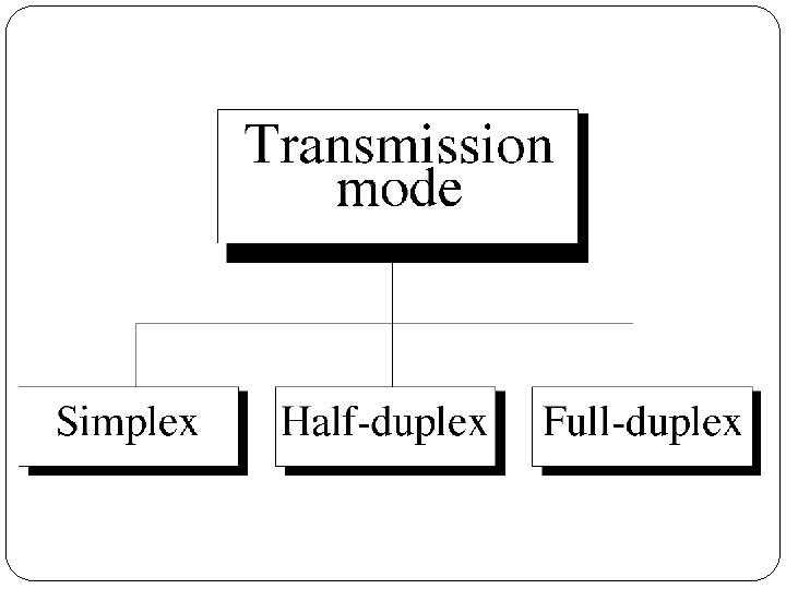
Simplex
Half-Duplex
Full-Duplex
• Network – Set of devices /nodes which are capable of communicating i. e send/receive data and are connected by communication links. (note link is here synonym for connection may be wired or wireless)
A network must be able to meet a certain criteria to make it effective
• Performance – is measured using transit time and response time. • Transit time – time taken to transfer data • Response time – time lapsed from request to receiving of data. • These depend on no. of factors like no. of users, type of medium, capability of H/W, Efficiency of S/W. • Throughput • Delay • Congestion
• Reliability – is measured by • frequency of failure, • time taken to recover from failure, • robustness of network during a catastrophe • Security • Protected data from unauthorized access, • protected data from damage, and • implementing necessary measures
• • • Line Configuration Topology Transmission Mode Categories of Networks Internetworks
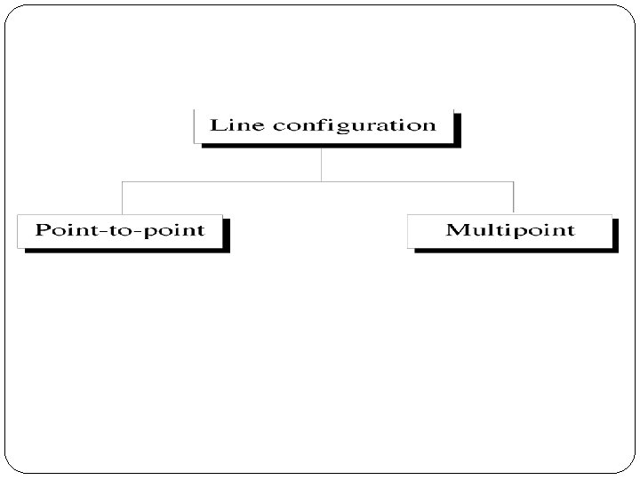
• Point – to – Point link • dedicated between two devices. • Entire capacity is reserved only for the two. • If wired – entire length of link is involved. • Wireless is also possible
Point-to-Point Line Configuration
Point-to-Point Line Configuration
Point-to-Point Line Configuration
• Multipoint link • Link is shared among more than two devices. • Entire capacity is shared either spatially or (temporally) time division. • Both Wired or Wireless are possible
Multipoint Line Configuration
Topology or Physical Topology refers to the way in which a network is laid out physically. – Geometric representation of all links and linking devices in a network.
Mesh Topology
• Mesh –dedicated – traffic between only connected devices • N nodes – each require N-1 links. So Total N* (N-1)/ 2 duplex links • Every device must have n-1 ports for linking • Robust • High speed • Costly • Meshy • Tough to maintain physically • Eg: Telephone Regional Office
Star Topology
• Mesh –dedicated – traffic between only connected devices • N nodes – each require N-1 links. So Total N* (N-1)/ 2 duplex links • Every device must have n-1 ports for linking • Robust • High speed • Costly • Meshy • Tough to maintain physically • Eg: Telephone Regional Office
Tree Topology
Bus Topology
Ring Topology
Hybrid Topology
CATEGORIES OF NETWORKS
• LAN – Local Area Network, • Privately Owned • Links devices in a building or campus. • Can be as simple as two devices to as complex as connecting different types of devices in an organization. • Extend upto few kilometers • Early speed – 4 to 16 Mbps • Today 100 -1000 Mbps • Common LAN topologies are Bus, Ring, Star
Local Area Network
Figure 1. 10 An isolated IAN connecting 12 computers to a hub in a closet
Local Area Network
• MAN – Metropolitan Area Network, • Next to LAN in size and service • Covers a city or a town. • Designed for high speed connectivity • Examples DSL , Cable TV, etc • Extended few 100 KM
Metropolitan Area Network
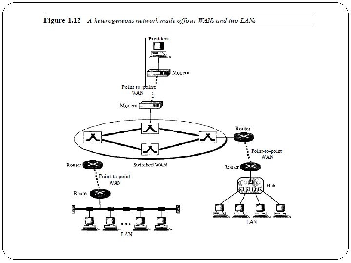
• WAN – Wide Area Network, • Provides long – distance transmission of data, image, audio, video etc over large geographical regions • Extend over countries • Can be as complex as backbone that connect the Internet (switched WAN) or as simple as a dial-up line that connects home computer to Internet (point-to-point WAN). • Switched WAN • Point-to-point WAN
WANs: a switched WAN v. a point-topoint WAN
Wide Area Network
Interconnection of Networks: Internetwork �When two or more networks are connected, they become an internetwork, or internet
THE INTERNET �The Internet is a structured, organized system. �An internet (note the lowercase letter i) is two or more networks that can communicate with each other. �The most notable internet is called the Internet (uppercase letter I), a collaboration of more than hundreds of thousands of interconnected network. �It is made up of many wide- and local-area networks joined by connecting devices and switching stations.
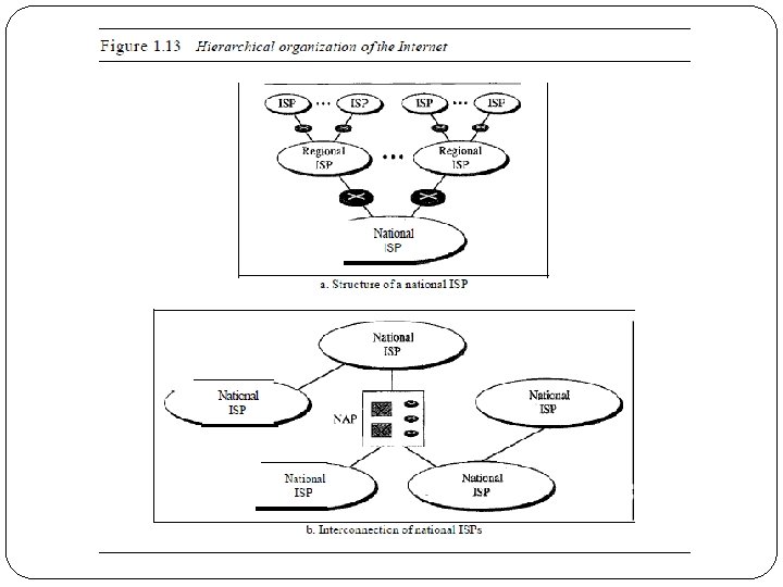
ISPs �International Internet Service Providers �National Internet Service Providers �Regional Internet Service Providers �Local Internet Service Providers
� International Internet Service Providers At the top of the hierarchy are the international service providers that connect nations together. � National Internet Service Providers The national Internet service providers are backbone networks created and maintained by specialized companies. Example: Sprint. Link, PSINet, UUNet Technology, AGIS, and internet Mel To provide connectivity between the end users, these backbone networks are connected by complex switching stations (normally run by a third party) called network access points (NAPs).
�Regional Internet Service Providers Regional internet service providers or regional ISPs are smaller ISPs that are connected to one or more national ISPs. �Local Internet Service Providers Local Internet service providers provide direct service to the end users. The local ISPs can be connected to regional ISPs or directly to national ISPs. Most end users are connected to the local ISPs.
Internetwork (internet)
Internet �Internet 55 is collobration of hundreds of of thousands of interconnected neworks. �In mid 1960, mainframes were standalone. The thought of computers from different manufacturers geographically separated to communicate lead to project ARPA – Advanced Research Projects Agency by researchers to share their research to avoid rework and reduce cost. �In 1967 at ACM, (Association for Computing Machinery) meeting, ARPA presented its ideas for ARPANET – a small network of connected computers.
ARPANET �A specialized computer – IMP Interface Message Processor is connected to hosts. �IMPs can communicate to each other and also with any type of computer( host) irrespective of manufacturer. �In 1969, it became reality �It connected 4 major universities: �University of California (@Los Angles) �University of California (@Berkeley) �University of Utah �Stanford Research Institute 56
ARPANET HOST Subnet 57 IMP HOST
ARPANET �ARPANET used software NCP ( Network Control 58 Protocol) to communicate between hosts. �In 1972, Vint Cerf, Bob Kahn, collobrated Internetting Project with more hosts involved. �In 1973, they proposed TCP which contained encapsulation, datagram and functions of gateway. �Shortly, this TCP is split into two protocols TCP and IP �IP- to handle routing, TCP to handle higher functions like segmentation, reassembly, error detection etc. �IP is also known as TCP/IP �This model of ARPANET expanded to 8 nodes, then 15 nodes and so on expanded to form today’s Internet.
Network Models
The OSI Model � Open Systems Interconnection (OSI). � Developed by the International Organization for Standardization (ISO). � Model for understanding and developing computer-to- computer communication architecture that is flexible, robust and interoperable. � It is not a protocol. � Developed in the 1980 s. � Divides network architecture into seven layers.
OSI � Each layer performs a subset of the required communication functions � Each layer relies on the next lower layer to perform more primitive functions � Each layer provides services to the next higher layer � Changes in one layer should not require changes in other layers � Layer 1, 2, 3 are the network support layer, deals with the physical aspects of moving data from one device to another. � Layer 5, 6, 7 are the user support layer, allow the interoperability among unrelated software. � Layer 4 ensures that what the lower layer have transmitted is in a form that the upper layers can use.
OSI layer � � � � Application layer Presentation layer Session layer Transport layer Network layer Data Link layer Physical layer
OSI layer
Protocol Data Units (PDU) � At each layer, protocols are used to communicate � Control information is added to user data at each layer � For example, the transport layer may fragment user data � Each fragment has a transport header added � Destination Address � Sequence number � Error detection code � This creates a transport protocol data unit (TPDU)
An exchange using the OSI model
Layer 1, 2, 3 Application Presentation Session Transport Network Data Link Physical Layer 3 Device Layer 2 and 3 addressing schemes needed and layer 1 addressing scheme is not needed Application Presentation Session Transport Network Data Link Physical
Layer 1: Physical Layer �Responsible of: �Transmitting individual bits from one to the next. �Physical characteristics of interface and media. �Representation of bits: a stream of bit(0 s, 1 s), �Data rate. �Synchronize of bits �Line configuration �Physical topology �Transmission mode
Physical Layer cont.
Layer 2: Data Link layer �Responsible of: � Moving frames from one hop (node) to the next. �Framing: divided the stream of bits received from the network layer manageable data units called frames. �Physical address (MAC address). �Flow control. �Error control: added trailer to the end of frame. �Access control. �Hop to hop delivery
Data Link layer cont. 10110110101 01100010011 10110000001
Hop-to-Hop delivery
Layer 3: Network Layer �The network layer is responsible: � The delivery of individual packets from the original source to the final destination. �Logical addressing: if the packet passes the network boundary we need another addressing system to help (source to destination) connection. �Routing : route or switch the packet to final destination. �Source-to-destination delivery (End-to-End).
Network Layer cont.
Source-to-Destination delivery
Layer 4: Transport Layer �The transport layer is responsible for: �Service point or Port addressing �Segmentation and reassembly : a message is divided into transmittable segments each segment containing a sequence no. �Connection Control: connection oriented or connectionless. �Flow control �Error control
Transport Layer cont.
Reliable process-to-process delivery of a message
Layer 5: Session Layer �Dialog control: design to establish, maintain, and synchronize the interaction between communicating systems. �Synchronization: it allows a process to add checkpoints or synchronization points to a data stream.
Session Layer cont.
Layer 6 : Presentation Layer �Design to the handle the syntax and semantic of the information exchanged between 2 systems. �And design for data translation, encryption, decryption, and compression.
Presentation Layer cont.
Layer 7: Application Layer �The application layer is responsible for providing services to the user. �Mail services �File transfer, access and management �Remote log-in or network virtual terminal �Accessing the World Wide Web �Directory service
Application Layer cont. SMTP Telnet HTTP
Summary
Application data stream Presentation data stream Session data stream Transport data Network Data link data Network header Frame H Network H data From trailer Physical 111011111101 Segments packets Frames Bits
TCP/IP Protocol Suite �The TCP/IP protocol suite is a hierarchical protocol , made of five layers: �Physical layer �Data link layer �Network layer �Transport layer �Application layer.
Some Protocols in TCP/IP Suite
TCP/IP PROTOCOL SUITE �The layers in the TCP/IP protocol suite do not exactly match those in the OSI model. �The original TCP/IP protocol suite was defined as having four layers: host-to-network, internet, transport, and application. �However, when TCP/IP is compared to OSI, we can say that the TCP/IP protocol suite is made of five layers: physical, data link, network, transport, and application.
TCP/IP and OSI model
TCP/IP PROTOCOL SUITE �TCP/IP Protocol suite is hierarchical model. �Physical and Data Link Layer – No specific protocol. It supports all standard properietary protocols. �Network Layer – (internetwork or internet layer) supports IP (internetworking protocol) and which in turn takes support from four other protocols �ARP- Address Resolution Protocol �RARP- Reverse Address Resolution Protocol �ICMP- Internetwork Control Message Protocol �IGMP- Internetwork Group Message Protocol
�IP (internetworking protocol) is the transmission mechanism used by TCP/IP protocols. �Unreliable and connectionless protocol �Best effort delivery – no error checking or tracking, but best effort to delivery �Data packing is called datagrams �ARP- Address Resolution Protocol – Mapping of Logical address to physical – to find physical address with logical �RARP- Reverse Address Resolution Protocol – to find logical address with physical address , when a device is connected to network for the first time or diskless computer is booted. �ICMP- Internetwork Control Message Protocol – send notifications about datagrams to sender �IGMP- Internetwork Group Message Protocol – to
�Transport Layer – to deliver messages from process to process. UDP – Simple , limited service TCP – Provides full transport layer services to applications SCTP – for new applicatons �Application Layer – Vast user application protocols are supported.
ADDRESSING �Four levels of addresses are used in an internet employing the TCP/IP protocols: physical address, logical address, port address and specific address.
Relationship of layers and addresses in TCP/IP SCTP: Stream Control Transmission Protocol TCP: Transmission Control Protocol UDP: User Datagram Protocol
Example 2. 1 �In Figure 2. 19 a node with physical address 10 sends a frame to a node with physical address 87. The two nodes are connected by a link (bus topology LAN). As the figure shows, the computer with physical address 10 is the sender, and the computer with physical address 87 is the receiver.
Example 2. 3 �Figure 2. 20 shows a part of an internet with two routers connecting three LANs. Each device (computer or router) has a pair of addresses (logical and physical) for each connection. In this case, each computer is connected to only one link and therefore has only one pair of addresses. Each router, however, is connected to three networks (only two are shown in the figure). So each router has three pairs of addresses, one for each connection.
Figure 2. 20 IP addresses
Example 2. 4 �Figure 2. 21 shows two computers communicating via the Internet. The sending computer is running three processes at this time with port addresses a, b, and c. The receiving computer is running two processes at this time with port addresses j and k. Process a in the sending computer needs to communicate with process j in the receiving computer. Note that although physical addresses change from hop to hop, logical and port addresses remain the same from the source to destination.
Figure 2. 21 Port addresses
DEVICES : 1. Repeaters, repeats signals that travels via long distance 2. Hub, a distributor that has a lot of ports which connected to computers. 3. Modem, a device that modulates a digital signal onto analog signal for transmission over telephone lines 4. Switches, like a hub but it transmit packets to hop/destination 5. Bridge, it is used to connect two similar LANs. 6. Routers, choose the best path to transmit the packet. 7. Gateway, is a network node connecting two networks that use different protocols. Can take several forms -- including routers or computers -- and can perform a variety of tasks.
Network devices With Layers Network Devices Application Layer Application gateway Transport Layer Transport gateway Network Layer Switch, Router and gateway Data link layer Bridge and Switch Physical Layer Repeater, Hub and Modem.
Network Devices
Repeater
Hub
Modem
Switch
Router
Bridge
NIC
RJ 45