CHAPTER 1 ELECTRONIC COMPONENTS Components Active versus Passive


 Classification based on the dielectric(Material) used: 1. Paper capacitor 2.")
 Classification based on polarization: 1. Non polarized type- No polarity. 2. Polarized type-")


 • Named for")


 chokes usually have ferromagnetic cores to increase")


- Slides: 51
CHAPTER -1 ELECTRONIC COMPONENTS
Components • Active versus Passive: • An active component supplies energy by converting one form of energy to another (eg. battery, transducer or transistor) • A passive component either only absorbs energy (eg. resistor, diode) or absorbs energy then later releases it (eg. capacitor or inductor)
1. 1 Resistors • Resistors are the most simple electronic devices. • A resistor is a passive two-terminal electrical component that implements electrical resistance as a circuit element. • Resistors act to reduce current flow, and, at the same time, act to lower voltage levels within circuits. • each time a current flows in a material, there is a resistance, depending both on the intrinsic characteristics of the material as well as its geometry, that opposes the current flow. • Resistors are components built to have a determined value of electrical resistance.
• Resistors are commonly used to perform two functions in a circuit. • The first use is to limit the flow of current in a circuit I=E/R I = 15 V / 30 Ω I = 0. 5 A
• Resistors are commonly used to perform two functions in a circuit. • The second use is to produce a voltage divider. A to B = 1. 5 V A to C = 7. 5 V A to D = 17. 5 V B to C = 6 V B to D = 16 V C to D = 10 V
Classification of Resistors
• Resistors can be either fixed or variable in value. • Fixed resistors come in a variety of different shapes, sizes and forms. • Axial lead resistors have the value of resistance printed on them or as a colour code • Surface mount resistors have a numerical code indicating a value • All resistors have a tolerance value
. * Material used for Resistors * Metal glazed resistors These are made by sintering on alumina or other substrates mixtures of metal or metal oxide with glass
Resistors general specification • Temperature coefficient: - it is defined as the increase in resistance per initial resistance when temperature is increased by 1°c. α=R 2 -R 1/R 1(t 2 -t 1) ppm/°c • Maximum voltage rating: -The max. voltage that can be applied to resistor without causing any damage is called the maximum voltage rating. • Tolerance: - The accuracy limits with resistors can be manufactured is known as tolerance. It is expressed in ± %.
Wire-wound Resistor • Wire-wound resistors are fixed resistors that are made by winding a piece of resistive wire around a ceramic core. These are used when a high power rating is required. • Wire or ribbon wound as a single layer helix over a ceramic or fiberglass core. Residual inductance. Low noise and quite stable with temperature (± 0. 5 -200 ppm/o. C) and R in [0. 1, 105 ] Ω.
Carbon Resistor • Carbon resistors are very popular for most applications because they are inexpensive and readily available in standard sizes and wattages. • Similar in construction to axial lead metal film resistors. The carbon film is a granular material, therefore random noise may be developed because of variations in the voltage drop between granules. Can affect circuits with low signals. ½ Watt 1 Watt 2 Watt
Metal film Resistor • Metal film resistors are another type of fixed resistor. These resistors are superior to carbon resistors because their ohmic value does not change with age and they have improved tolerance. • Printed circuits using a thin layer of resistance alloy on a flat or tubular insulating substrate. Characteristics similar to wirewound resistors.
Colour coding of Resistors colour Significant Figure Decimal multiplier Tolerance ±% Black 0 1 - Brown 1 10 - Red 2 102 - Orange 3 103 - Yellow 4 104 - Green 5 105 - Bule 6 106 - Violet 7 107 - Gray 8 108 - White 9 109 - Gold - 0. 1 5 Silver - 0. 01 10 No colour - - 20
Resistors Resistor colour code calculation • The first band red has a value of 2 • The second band purple has a value of 7 2 • The third band has a multiplier of x 10 7 • The last band indicates a tolerance value of +/-5% • Resistance value is 270Ω +/-5% x 10
Light Dependent Resistor • The light dependent resistor consists of a length of material (cadmium sulphide) whose resistance changes according to the light level. • Therefore the brighter the light, the lower the resistance.
Principle of Operation • An LDR is made of a high resistance semiconductor. • If light falling on the device is of high enough frequency, photons absorbed by the semiconductor give bound electrons enough energy to jump into the conduction band. • The resulting free electron (and its hole partner) conduct electricity, thereby lowering resistance.
LDR Applications • • Smoke detection Automatic lighting Clock Radios Alarm systems Dynamic Compressors Solar Street Lamps Camera Light meters
Difference Between R and C Like resistors, capacitors can impede the flow of current. Unlike resistors, which resist the flow of both DC and AC currents in exactly the same way, capacitors can be used to COMPLETELY BLOCK the flow of DC currents. As the frequency of the alternations associated with the flow of AC currents increases, capacitors impede the flow of current to a lesser degree! High Frequency Low Frequency
1. 2 CAPACITORS • A basic capacitor has two parallel plates separated by an insulating material • A capacitor stores an electrical charge between the two plates • The unit of capacitance is Farads (F) • Capacitance values are normally smaller, such as µF, n. F or p. F • Capacitance is a measure of a capacitor’s ability to store charge on its plates. • A capacitor has a capacitance of 1 farad (F) if 1 coulomb (C) of charge is deposited on the plates by a potential difference of 1 volt across its plates.
• For a given capacitor the stored charge q is directly proportional to the voltage across it V • The constant of proportionality is the capacitance C and thus +q -q
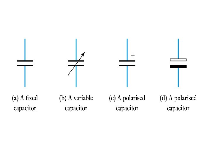
Classification of capacitors (A) Classification based on the dielectric(Material) used: 1. Paper capacitor 2. Ceramic capacitor 3. Mica capacitor 4. Plastic capacitor 5. Glass capacitor 6. Air capacitor 7. Vaccume capacitor (B) Classification based on the variability: 1. Fixed capacitor- can not be changed. 2. Variable capacitor- can be changed continuously. 3. Trimmer- Used for adjustment &then left undisturbed.
(C) Classification based on polarization: 1. Non polarized type- No polarity. 2. Polarized type- has polarity. *Specification of capacitor: 1. Value 2. Type 3. Polarized or non-polarized 4. Fixed or variable 5. Voltage rating 6. Power factor 7. Arrangement of leads 8. Temperature coefficient in ppm/°C 9. Maximum operating temperature.
Ceramic Disc Capacitor • Ceramic Capacitors or Disc Capacitors as they are generally called, are made by coating two sides of a small porcelain or ceramic disc with silver and are then stacked together to make a capacitor. • For very low capacitance values a single ceramic disc of about 3 -6 mm is used. • Ceramic capacitors have a high dielectric constant (High-K) and are available so that relatively high capacitance’s can be obtained in a small physical size.
Specification & Application of Disc • Flat circular disc ceramic (Z 5 U dielectric, high K) capacitors have a 2000 V dc, 550 V ac rating with capacitances of up to 47 n. F. • An exploitable drawback of such a ceramic capacitor is that its permittivity decreases with increased voltage. That is, the capacitance decreases with increased voltage. • Such a capacitor can be used in the turn-off snubber for the GTO thyristor and diodes. • The capacitperformed by a saturable reactor. • Advantageously, the disc ceramic capacitor has low inductance, but the high dissipation factor may limit the frequency of operation. Multi-layer ceramic capacitors can be used in switched mode power supply input and output filters.
Aluminum electrolytic capacitor • There are basically two types of Aluminium Electrolytic Capacitor, the plain foil type and the etched foil type. The thickness of the aluminium oxide film and high breakdown voltage give these capacitors very high capacitance values for their size. • The etched foil type differs from the plain foil type in that the aluminium oxide on the anode and cathode foils has been chemically etched to increase its surface area and permittivity.
• This gives a smaller sized capacitor than a plain foil type of equivalent value but has the disadvantage of not being able to withstand high DC currents compared to the plain type. • Also their tolerance range is quite large at up to 20%. Typical values of capacitance for an aluminium electrolytic capacitor range from 1 u. F up to 47, 000 u. F.
Variable capacitor • Variable capacitors may have their capacitance changed by mechanical motion. Generally two versions of variable capacitors has to be to distinguished • Tuning capacitor – variable capacitor for intentionally and repeatedly tuning an oscillator circuit in a radio or another tuned circuit • Trimmer capacitor – small variable capacitor usually for onetime oscillator circuit internal adjustment
Mica, PVC & Air gang capacitor Small trimmer capacitors, adjustable with special trimming tools (DON´T use a screwdriver!) by technicians rather than the equipment user are available in a variety of very small designs. They work in a similar way to the larger variables, with tiny rotating plates and typically PVC film dielectric layers between. Their capacitance is only a few pico farads and they are often used in conjunction with larger variable capacitors (and even fitted inside the case of tuning capacitors) to improve accuracy
• The dielectric mica is a mineral which has a plane of easy cleavage enabling large sheets of single crystal to be split into thin plates, typically 50 µm thick. Stacks of mica plates are interleaved with silver metal foils • Air-gap capacitors use air as the dielectric medium. The distance between the plates can be varied to change the capacitance. The capacitance values offered are high and can be used with high voltages. These are used for high frequency operations in communication system.
Properties and applications of Mica • Mica capacitors are non-polar, low loss, and stable up to about 30 MHz, where the lead length and electrodes dominate as inductance. • Maximum ratings are a few nanofarads at 5000 V, with dissipation factors of 0. 1 per cent at 1 k. Hz. For capacitance less than 1 n. F, a 0. 1 per cent dissipation factor is obtainable at 1 MHz. • An insulation resistance of 105 MΩ at 20°C down to 104 MΩ at 125°C is common for capacitance to 10 n. F, after which resistance falls off. • Typical operating temperature range is from -55°C to 125°C, with a capacitance temperature coefficient of 0 to +70 ppm/K. • This rating may range between 1. 6 m. A/p. F for smaller packages (9× 8× 8 mm) down to 0. 12 m. A/p. F for larger packages (44× 32× 33 mm). • A maximum VA limit must also be observed, typically 50 VA for smaller sizes up to 820 VA for the larger size
Coding of capacitor-using numerals • the digits 102 would indicate 10 and 2 zero’s in pico-farads which is equivalent to 1, 000 p. F. • So on the image of the ceramic capacitor above the numbers 154 indicate 15 and 4 zero’s in pico-farads which is equivalent to 150, 000 p. F or 150 n. F or 0. 15 u. F. Letter codes are sometimes used to indicate their tolerance value such as: J = 5%, K = 10% or M = 20% etc.
Colour band system for capacitor
https: //www. google. co. in/search? q=colour+coding+of+capacitors&biw=1366&bih=667&tbm=isch&imgil=3 y. XBPr 7 -TQXs 4 M%253 A%253 Buz. Nw 99 ynb. Cx 6 TM%253 Bhttp%25253 A%252 52 F%25252 Fwww. tpub. com%25252 Fneets%25252 Fbook 2%25252 F 3 g. htm&source=iu&pf=m&fir=3 y. XBPr 7 -TQXs 4 M%253 A%252 Cuz. Nw 99 ynb. Cx 6 TM%252 C_&usg=__JRkmas. Ww. Ps_M 8 DNGMFTZI 8 Rl. Rg%3 D&ved=0 CDAQyjc&ei=8 IGKVc. W 7 H 4 Phu. QSN 9 YKg. Dg#imgrc=Uv-h. Zig. Gso. Ro. GM%253 A%3 Bca 0 Eiwc. Snu. Tt 0 M%3 Bhttp%253 A%252 Fslfisica. host 22. com%252 Fco digo_philips_01. jpg%3 Bhttp%253 A%252 Fslfisica. host 22. com%252 Fcolores. html%3 B 1648%3 B 1232&usg=__JRkmas. Ww. Ps_-M 8 DNGMFTZI 8 Rl. Rg%3 D
1. 3 INDUCTORS • Faradays laws of electromagnetic induction: • Faraday's First Law: • Any change in the magnetic field of a coil of wire will cause an emf to be induced in the coil. This emf induced is called induced emf and if the conductor circuit is closed, the current will also circulate through the circuit and this current is called induced current. Method to change magnetic field: • 1. By moving a magnet towards or away from the coil • 2. By moving the coil into or out of the magnetic field. • 3. By changing the area of a coil placed in the magnetic field • 4. By rotating the coil relative to the magnet.
• Faraday's Second Law: • It states that the magnitude of emf induced in the coil is equal to the rate of change of flux that linkages with the coil. The flux linkage of the coil is the product of number of turns in the coil and flux associated with the coil.
Self-Inductance • When the switch is closed, the current does not immediately reach its maximum value. • Faraday’s law can be used to describe the effect. • As the current increases with time, the magnetic flux through the circuit loop due to this current also increases with time. • This increasing flux creates an induced emf in the circuit.
• The direction of the induced emf is such that it would cause an induced current in the loop which would establish a magnetic field opposing the change in the original magnetic field • The direction of the induced emf is opposite the direction of the emf of the battery • This results in a gradual increase in the current to its final equilibrium value. • This effect is called self-inductance – Because the changing flux through the circuit and the resultant induced emf arise from the circuit itself • The emf εL is called a self-induced emf
• An induced emf is always proportional to the time rate of change of the current – The emf is proportional to the flux, which is proportional to the field and the field is proportional to the current • L is a constant of proportionality called the inductance of the coil and it depends on the geometry of the coil and other physical characteristics • A closely spaced coil of N turns carrying current I has an inductance of • The inductance is a measure of the opposition to a change in current.
• The SI unit of inductance is the henry (H) • Named for Joseph Henry • Assume a uniformly wound solenoid having N turns and length ℓ – Assume ℓ is much greater than the radius of the solenoid • The flux through each turn of area A is The inductance is • This shows that L depends on the geometry of the object.
Mutual Inductance • The magnetic flux through the area enclosed by a circuit often varies with time because of time-varying currents in nearby circuits • This process is known as mutual induction because it depends on the interaction of two circuits • The current in coil 1 sets up a magnetic field • Some of the magnetic field lines pass through coil 2 • Coil 1 has a current I 1 and N 1 turns • Coil 2 has N 2 turns
• The mutual inductance M 12 of coil 2 with respect to coil 1 is • Mutual inductance depends on the geometry of both circuits and on their orientation with respect to each other • If current I 1 varies with time, the emf induced by coil 1 in coil 2 is • If the current is in coil 2, there is a mutual inductance M 21 • If current 2 varies with time, the emf induced by coil 2 in coil 1 is
• In mutual induction, the emf induced in one coil is always proportional to the rate at which the current in the other coil is changing • The mutual inductance in one coil is equal to the mutual inductance in the other coil – M 12 = M 21 = M • The induced emf’s can be expressed as
The Coupling Coefficient • The coils and mutual inductances depend on material properties of the core. The factor c used represents these properties in a lumped product. Explicity, c is the product of the permeability of free space and the core, the cross-sectional area, and the inverse of the length of the coils. • c = μ 0μr. A/l • the mutual inductance is related to the coils inductances by • M= • Some flux lines will not cut through the coupled inductor, which will affect the mutual inductance. Therefore, eq is multiplied by the coupling coefficient k, a value between 1 (perfectly linked inductors) and 0 (uncoupled inductors). Eq. Becomes • M=K
Q factor of a coil • Coil has inductance and when it is connected to a. c. supply, it offers inductive reactance XL=2πf. L. • Coil is made up of copper wire, so it offers resistance R. • Quality factor of a coil is the ratio of its inductive reactance and resistance. • Q = XL/R = ωL/R = 2πf. L/R.
Air core inductor • An inductor, also called a coil or reactor, is a passive twoterminal electrical component which resists changes in electric current passing through it. • It consists of a conductor such as a wire, usually wound into a coil. When a current flows through it, energy is stored temporarily in a magnetic field in the coil. • When the current flowing through an inductor changes, the time-varying magnetic field induces a voltage in the conductor, according to Faraday’s law of electromagnetic induction, which opposes the change in current that created it. • As a result, inductors always oppose a change in current, in the same way that a flywheel oppose a change in rotational velocity. • They are also used in electronic filters to separate signals of different frequencies, and in combination with capacitors to make tuned circuits, used to tune radio and TV receivers.
Iron core inductor • Often, iron core inductors are the solution when space is limited. Iron core inductors offer high capacity in a varied range of sizes. We design and manufacture iron core inductors using iron or special alloys. Agile Magnetics has supplied iron core inductors for use in a variety of applications including, AC load banks, audio equipment, high energy physics, industrial power supplies, inverter systems, power conditioning, rapid transit, and many others.
Ferrite core inductor • Ferrite is a magnetic material which consists of a mixed oxide of iron and other elements that are made to have crystalline molecular structure. • The crystalline structure is created by f ring the ferrite material at a very high temperature for a specifed amount of time and profle. • The general composition of ferrites is xx. Fe 2 O 4 where xx represents several metals. The most popular metal combinations are manganese and zinc (Mn. Zn), and nickel and zinc (ni. Zn). • These metals can be easily magnetized
AF, RF Inductor • Audio frequency (AF) chokes usually have ferromagnetic cores to increase their inductance. They are often constructed similarly to transformers, with laminated iron cores. A major use in the past was in power supplies to produce direct current (DC), where they were used in conjunction with large electrolytic capacitors as filters to remove the alternating current (AC) ripple at the output of rectifiers • Another name is radio frequency of RF inductors. This type operates at high frequency ranges. It is characterized by low current rating and high electrical resistance. However, it suffers from a proximity effect, where the wire resistance increases at high frequencies. Skin effect, where the wire resistance to high frequency is greater than the electrical resistance of current direct.
Toroidal Core Inductor • Toroidal Inductor constructs of a circular ringformed magnetic core that characterized by it is magnetic with high permeability material like iron powder, for which the wire wounded to get inductor. It works pretty well in AC electronic circuits' application. • The advantage of this type is that, due to its symmetry, it has a minimum loss in magnetic flux; therefore it radiates less electromagnetic interference near circuits or devices. Electromagnetic interference is very important in electronics that require high fr • equency and low power.
Applications of Inductors • • • 1. Energy Storage 2. Sensors 3. Transformers 4. Filters 5. Motors