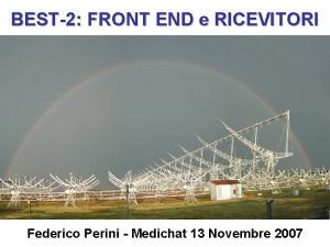
WPRX Status May 2016 Monari Jader Perini Federico


- Slides: 41

WP-RX Status May 2016 Monari Jader – Perini Federico INAF-IRA Radiotelescopio Croce del Nord Sasso Marconi of 9 th-13 th of May 2016

AADC participation Davide Fierro Giuseppe Virone Jader Monari

Italian SKA-low – Dream Team Davide Fierro PM SKA Italia Jader Monari Technical LFAA coordinator Roma Headquarter IRA Pietro Bolli Federico Perini Marco Schiaffino Francesco Schillirò Mechanics Acquisition System OAA IRA OACT Antenna & Calibration Receiver SKA Italian Manager& LFAA board member: Davide Fierro Coordination & RX WP leader : Jader Monari Antenna & Calibration: Pietro Bolli, Giuseppe Pupillo Receiver Chain: Federico Perini, Simone Rusticelli, Marco Poloni Mechanics: Marco Schiaffino Signal Processing: Francesco Schillirò, Monica Alderighi Giovanni Naldi, Andrea Mattan Firmware: Gianni Comoretto, Carolina Belli, Simone Chiarucci Admistration: Alice Tabellini Gianni Comoretto Firware OAA SAD : Matteo Murgia, Federica Govoni, Tonino Pisanu, Giampaolo Serra, Francesco Gaudiomonte, Ignazio Porceddu, Lino Morongiu

Research & Industrial Contracts (2015 -2016) Uni. BO Analogue Optical fibre Giovanni Tartarini, Antenna & Calibration • CNR-IEIIT & POLITO (WP-AL) • UNIBO (WP-RX) • UNIFI (WP-RX) CNR-IEIIT Flying measure facility POLITO Uni. Fi • • Lightech & OPTEL (WP-RX) Sanitas EG (WP-SP) Finmeccanica (WP-RX) Campera ES (WP-SP) Giuseppe Virone, Augusto Olivieri, Fabio Paonessa Andrea Lingua, Marco Piras, Paolo Maschio, Reliability Marcantonio Catelani

Main Past Activities • Vivaldi design • Hexacopter test bench • RFo. F technology (standard, WDM, VCSEL, POF) • Pattern measurement/Calibration for Vivaldi/SKALA, Mini MAD, MAD-1, 2, 3 • i. TPM

Verification systems (2015 -2016) 1. 2. 3. 4. 5. Pre-AAVS 1 (16 SKALA Lord Bridge) – 2015 BAD (16 Vivaldi Medicina) SAD (128 Vivaldi SRT) – 2016 Pre-AAVS 1 (16 SKALA MRO) - 2016 AAVS 1 (384 SKALA MRO) -2016 (December)

INAF AADC participation Costs (2012 -2016) Year FTE (1=66 K€) Cash Industry Contract Travel 2012 -2013 10. 39 185 K 0 20 K 2013 -2014 9. 6 256 K 100 K 2014 -2015 9. 84 214 K 0 49. 8 K 2015 -2016 8. 69 152. 2 K 589. 3 K 41 K Maybe more: Administration tenders Comoretto 2012 to 2015 4. 17 M€

WP-RX LNA RF Circuitry FEM WP Receiver TX RX RF Circuitry Link RFo. F PREADU

Documents delivered (PDR, DDR)

Documents delivered (SKAO) Date Nominal date Deliverable T 0 1 st Nov 2013 Bid preparation and SKAO delivery of Level 1 requirements € 0, 5 M T 0+12 weeks 1 st Feb 2014 TBD and TBC agreed and closed for Level 1 requirements € 1 M T 0+25 weeks 1 st May 2014 Preliminary report on RFo. F cost and performance € 1 M T 0+34 weeks 1 st July 2014 Preliminary installation plan (including demonstration plan) T 0+38 weeks T 0+46 weeks 1 st August 2014 Mid Sept 2014 T 0+50 weeks End of 2014 T 0+68 weeks 1 st Oct March 2015 Total Earned Value Preliminary power design report System Requirements documents (see SEP) Review € 1 M and associated Preliminary Design Review and associated documents (see SEP) Closure of Stage 1 € 0, 5 M Nominal date Deliverable 15 st April 2015 Kick-off Stage 2 € 1 M 12 th Oct 2015 AA Verification System 1 (AAVS 1) Detailed Design Review € 2 M 15 th 2016 Preliminary installation plan of a LFAA station € 0, 5 M 1 st July 2016 Installation plan of a LFAA station € 0. 5 M 1 st May 2016 Report on RFo. F performance over the max. length expected for both surface laid and trenched cable to demonstrate achieving the stability requirements. 1 st Aug 2016 Installation and functional test report of AAVS 1 1 st March Feb 2017 Earned Value € 1 M € 1. 5 M Validation and evaluation report of AAVS 1 € 2 M 1 st April 2017 CDR SKA 1 € 3 M 30 th Closure of Stage 2 € 1, 7 M 31 st Dec 2015 LFAA station design report and Technical compliance update € 1. 0 M 10 th July 2 2015 PMP and SEMP review € 0. 5 M 15 th Sept 2015 Inputs to SKAO System Review Updated costs € 1. 0 M July 2017 € 2 M € 1 M € 0, 6 M € 7, 6 M Total External ICDs Risk review Draft RAM and ILS report € 15. 7 M

Tenders for AAVS 1

Prototypes developed RFo. F links PREADU 1. 0 PREADU 2. 0 With integrated ORX

Mechanics works

Main on going activities 1. 2. 3. 4. Production for AAVS 1 Benches and JIG preparation Reliability Long links up to 70 Km

1. AAVS 1 Production 320 Hybrid Cables (440 necessary) 49 K€ 400 + 40 RFo. F FE/WDM OTX 50 + 5 Complete PREADU 2. 1 boards 20 ADU (i. TPM) 244 K€ 6 Subrack + metal works for i. TPM 10 K€ + pre. AAVS 1 Cambridge and pre. AAVS 1 Australia 244 K€ 30 K€

1. Production and Testing (RX) Production (1) First tranche (40 FE modules / 5 pre. ADU) Production (2) Second tranche (380 FE / 50 pre. ADU) T 0 August time Dec

1. Gantt Chart No EMC pre-compliance test considered

2. Benches and JIG preparation

3. Reliability preliminary results

4. Long Links main results Main topics related to the fibre length: • Attenuation • Relative phase variation due to temperature changes and nonlinearity due to chromatic dispersion.

News from the Lab Update of the most recent results towards AAVS 1

From PREADU 1. 0 to 2. 0 (February 2016) • • • Demonstration of integration of 16 RF chains ORX detachable RF receivers mounted on the carrier PCB SPI or Dip Switches RX control Designed to meet RF PDR specifications • • • Same size of 1. 0 Both ORX and RF modules are detachable Easier replacement SPI and Dip Switches RX control Improved RF specifications to meet DDR specifications (also in the FE/OTX)

RX WP Specifications FE/OTX Up to 10 Km SMF G 652 D ORX RX(RFo. F) RF RX(RF) RX Sub. Assembly Sub. Element Needed also for national tender specs definition

RFo. F Links specifications RF band Values 50 -650 MHz Min: 20 d. B Gain Typ: 25 d. B Notes Freq=100 MHz and with 10 Km of G 652 D SMF between OTX and ORX Max: 30 d. B 10 Km links Flatness +/-0. 5 d. B IRL ORL >15 d. B (>10 d. B) NF <18 d. B RF channels isolation Out of band rejection Measured in two separate sub-bands: 50 -375 MHz and 375 -650 MHz 50 -350 MHz (350 -650 MHz) Over full 50 -650 MHz band with 10 Km of G 652 D SMF between OTX and ORX Measured as difference of the gains at the two outputs with the same input. >30 d. B ≥ 50 d. B OP 1 d. B >+8 d. Bm OIP 3 >+21 d. Bm Freq ≤ 20 MHz Over full 50 -650 MHz band and with 10 Km of G 652 D SMF between OTX and ORX >+30 d. Bm G<28 d. B for >+33 d. Bm for OIP 2 Freq>100 MHz and with 10 Km of G 652 D SMF between OTX and ORX

WDM – Wavelength Division Multiplex 2 Laser in 2 separate packages 2 separate FO Same (1310 OR 1550 nm) 2 PD in 2 separate packages Pol 1 Pol 2 Pol 1 2 Laser with a WDM combiner integrated in a single package Pol 2 Same FO, different 1310 AND 1550 nm (1270 AND 1330 nm) Pol 2 2 PD with a WDM splitter integrated in a single package

WDM – Wavelength Division Multiplex J The RF circuits remain the same as for the standard (two separate LASER and PD in separate packages). J Half FO, connectors, fusion splices, fibre joints. J Optical isolation doesn’t limit the RF isolation. K WDM LASER and PD costs are similar to 2 LASER and 2 PD main cost saving is on FO, connectors, joints, … K Different dispersion for G 652 D SMF at 1310 and 1550 nm but with closer wavelengths selection the problem can be fixed (i. e. 1270 and 1330 nm)

RFo. F evolution (options) 60 d. B 40 d. B 50 d. B! February 2016 Dotted = CH 1/1310 nm Solid = CH 2/1310 nm Dotted = 1310 nm Solid = 1550 nm Dotted = 1330 nm Solid = 1270 nm Standard WDM 1310/1550 WDM 1290/1330

WDM 1270/1330 pre-production meas. A full RF characterization (as performed for 1310/1550 version) is still undergoing Completed over full temperature range -10 to +70°C for / T coefficients Link# 1 2 3 4 5 6 7 8 / T (1270 nm) [nm/°C] 0. 0871 0. 0866 0. 0863 0. 0874 0. 0879 0. 0877 0. 0858 0. 0862 / T (1330 nm) [nm/°C] 0. 0909 0. 0910 0. 0906 0. 0911 0. 0913 0. 0920 0. 0901 0. 0900

WDM 1270/1330 pre-production meas. OP 1 d. B Completed at +25°C for RF (S-parameters, NF, P 1 d. B and IP 2/IP 3) with and without 10 Km of G 652 D SMF optical fibre between TX and RX needs to be performed at least at -10°C and +70°C 0 m Link # 1 2 3 4 5 6 7 8 10 km 1270 nm 1330 nm 100 MHz 450 MHz 14. 9 15. 7 15. 4 14. 9 13. 2 15. 1 14. 4 13. 9 14. 2 15. 4 14. 8 14. 3 12. 3 14. 6 13. 8 12. 9 17. 2 14. 9 15. 1 14. 2 15. 1 15. 3 14. 7 14. 3 16. 1 14. 3 14. 5 13. 7 14. 6 14. 5 14. 1 13. 9 14. 0 13. 9 14. 7 14. 0 13. 6 14. 2 13. 5 12. 3 13. 2 13. 5 14. 4 13. 7 13. 3 13. 8 13. 1 12. 2 14. 8 13. 3 12. 5 12. 7 14. 3 12. 3 13. 5 13. 6 13. 7 13. 1 12. 3 14. 1 14. 0 12. 9 13. 3

WDM 1270/1330 pre-production meas.

RF receiver specifications RF Specifications Overall RF Band Values 50 -650 MHz LB Filter 0 -350 MHz 375 MHz) 50 d. B 375 -650 MHz 50 d. B Min: 26 d. B LB Filter Rejection HB Filter Rejection Gain Typ: 27 d. B Flatness Max: 28 d. B +/-0. 5 d. B IRL ORL NF >15 d. B (>10 d. B) <10 d. B RF channels isolation >50 d. B OP 1 d. B >+17. 5 d. Bm OIP 3 >+31 d. Bm OIP 2 >+41 d. Bm Notes Split in two sub-bands: LB 0 -375 MHz and HB 375 -650 MHz (50 - 1 d. B band (3 d. B band) Freq ≥ 450 MHz 1 d. B band Freq ≤ 325 MHz & Freq ≥ 750 MHz The receiver chain shall include a 5 bit (031 d. Ba) digital step attenuator (DSA). Freq=100 MHz with DSA at minimum level of attenuation (0 d. B). Measured in the two separate sub-bands: 50375 MHz and 375 -650 MHz 50 -375 MHz (375 -650 MHz) Freq=350 MHz with DSA at minimum level of attenuation (0 d. Ba) Measured as difference of the gains of two adjacent outputs with the same input and with all DSA at minimum level of attenuation over 50 -350 MHz band Over 50 -350 MHz band and with DSA at minimum level of attenuation Over 50 -350 MHz band with DSA at

RF receiver 2. 0 schematic SKY/50 Ohm Switch 2 nd Gain Block Equalization/PAD New RF switches from Peregrine (PE 4251) and new DSA from RFMD (RFSA 3714): cheaper and easier to procure than Hittite and Minicircuits ones 1 st Gain Block Filters Bank 31 d. B/1 d. B Step Attenuator

RF receiver 2. 0 measurements CH ISOLATION HIGH Band LOW Band S-parameters

RF receiver 2. 0 measurements

RX 2. 0 Power Consumption FE/OTX First RX Specification (@+50°C): 0. 5 W (FE) + 0. 5 W (PREADU) = 1 W Total (FE+PREADU) consumption for each single polarisation/RX chain: 0. 35 W+0. 6 W = 0. 95 W @+50°C 0. 42 W+0. 6 W = 1. 02 W @ +70°C Phase Switch Idc (m. A) ORX 66 Filter Bank RF Switch PE 4251 0. 055 Dig. Att RFSA 3714 0. 18 Vdc (V) Vldo (V) 3. 5 3. 3 Pdc (W) Pldo (W) 0. 59 0. 54 Gain Block AWG-0015 34 Gain Block AWG-1017 70 PREADU 2. 0 168. 35 PREADU 2. 0@25°C

Why PREADU 2. 1 for AAVS 1? ORX RF MMCX coaxial connector broken

PREADU 2. 1 for AAVS 1 • • • One single PCB and shielding enclosure for both ORX and RF No more coax connectors between ORX and RF receiver Same size, controls and performance than ORX+RF

Final RX specs for national tender Parameter RF band Low Band (LB) High Band (HB) Flatness HP filter rejection LB filter rejection Value 50 -650 MHz 50 -375 MHz 375 -650 MHz +/-1. 5 d. B ≥ 45 d. B Notes Overall frequency band 3 d. B cut frequency Measured in the two separate sub-bands LB and HB Freq≤ 20 MHz, HP filter integrated in the FE PCA Freq≥ 450 MHz, LB filter integrated in the PREADU PCA HB filter rejection IRL ≥ 45 d. B Min 54 d. B Typ 60 d. B Max 66 d. B >12 d. B Freq≤ 325 MHz & Freq≥ 750 MHz, HB filter integrated in the PREADU PCA Freq=100 MHz FE and ORX connected directly DSA set at minimum attenuation level Measured at both FE inputs on the overall RF band 50 -650 MHz. ORL >12 d. B NF <16 d. B RF channels isolation >30 d. B OP 1 d. B >+17 d. Bm OIP 3 >+18 d. Bm OIP 2 >+38 d. Bm Measured at both ORX+RF outputs on the two sub-bands LB and HB. Measured in the two sub-bands LB e HB FE and ORX connected directly DSA set at minimum attenuation level Defined as the difference of the gains measured at the two PREADU PCA outputs with the same FE PCA input on both LB and HB bands. DSA set at minimum attenuation level Freq=100 MHz FE and ORX connected directly Gain

Critical issues • Requirements and Analysis not completed yet • No reliability studies considered so far (maintenance may suffers) • Costing • International Scientific groups not involved so far (AAVS 1) • IP and its protection not clear

Technology Maturity • Rack design Cooling system, Clocks Distribution, main PSU, Routing & Cabling • Software/Firmware design • Connection antenna end not optimized • Monitoring at APIU level (maintenance) • PREADU & ADU assembly Self RFI, RFI acceptable for Australian regulations

Conclusions Much has been done since the beginning of the project up to now and the results achieved are remarkable. But we are aware of the fact that, time and expertise are needed to reach the technological maturity that this extraordinary project requires. In particular is unavoidable and needed an end to end homogenization of all parts and development towards engineering for SKAlow (ITF).
 Federico perini
 Moszna
 Rosanna perini
 Diego perini cern
 Zmail utd
 Enmme
Enmme Paragraph formatting
 Mutual fund returns may be granted pass-through status if
 Hci design patterns
 The joint pricing
 Itc federico cesi terni
 Federico albano leoni
 Federico efron
 Federico ii
 Federico carbonell
 Lluvia federico garcia lorca
 Federico etro
 Jorge martn
 Istituto trento 5
 Obras de federico froebel
 Federico calzolari
 Federico capoani
 Romancero gitano temas
 Tú eres (less) simpático que federico.
 Federico verga
 Federico lucarelli
 Federico werbung
 Molly leiwant
 Frank federico
 Liceo federico albert faupp
 Federico mongelli
 Escuela de postgrado federico villarreal
 Giovanni de medici
 Itc federico cesi terni
 La natividad
 Institucion educativa federico carrasquilla
 Poema balada de los abuelos
 Federico magalini
 Federico echevarriaren hitzaldia iruzkina
 Export vmware to proxmox
 Riflessione totale
 Federico marulli
