STHE as Closed Feed water Heater P M


 proposed")


- Slides: 56
STHE as Closed Feed water Heater P M V Subbarao Professor Mechanical Engineering Department I I T Delhi A Three in One STHE !!!
Thermodynamic Analysis of A Power Plant Regeneration
Train of Shell & Tube HXs.
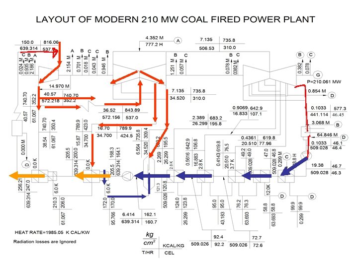
Power Plants for Future : Mid 2013: Denmark
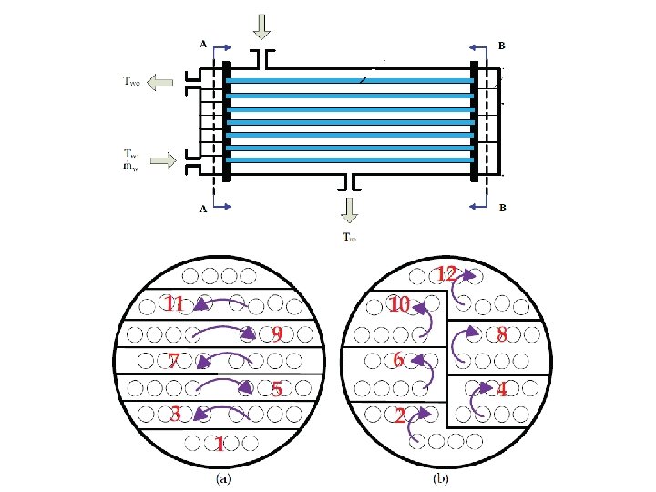
Mass flows through CFWH
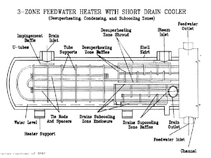
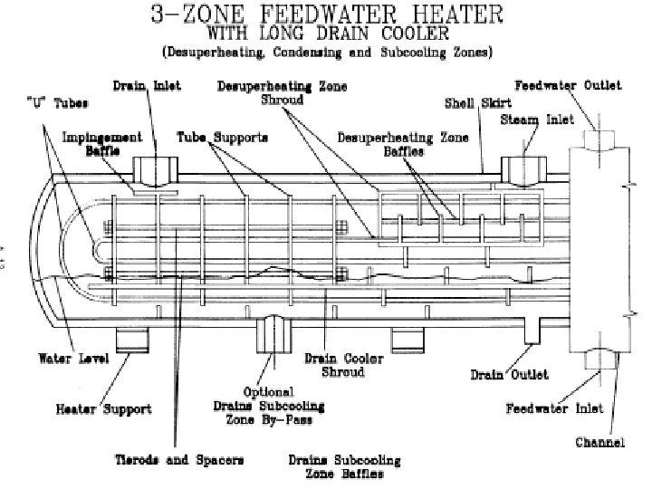
Special Anatomy of CFWHs • The economic analysis of the heaters should consider a desuperheater section when there is a high degree of superheat in the steam to the heater and an internal or external drain cooler to reduce drains below steam saturation temperature • Type: The feedwater heaters will be of the U-tube type. • Location: Heaters will be located to allow easy access for reading and maintaining heater instrumentation and for pulling the tube bundle or heater shell. • High pressure heaters will be located to provide the best economic balance of high pressure feedwater piping, steam piping and heater drain piping.
HP Closed Feed Water Heater
LP Closed Feed Water Heater
High Pressure CFWH • • • A HP Closed Feedwater Heater has three zones: Desuperheating zone. Condensing Zone. Drain cooling Zone. Each zone is designed as a separate heat exchanger and heat transfer coefficients and pressure drops are evaluated separately.
Thermodynamic Layout of HP Closed Feed Water Heater HP Turbine Tbi, pbi, Tbsi Condensing Shell Drain Cooler Desuperheater Tfi+1 TRAP
Bleed Steam Feed Water in C=Condenser DC C DS Feed Water out Feedwater heater with Drain cooler and Desuperheater Condensate DC=Drain cooler DS=Desuperheater Bled steam TTD T -TTD=Terminal temperature difference C DC DS L
Design of Condensers and Condensing Zones Lowest Shell side Thermal Resistance !!!
Basic Anatomy of Condenser
Basics of Condensation • The heat is removed by contacting vapor with a cold surface (the tube wall). • The liquid then flows off the tube under the influence of gravity, collects, and flows out of the exchanger. • In some cases, vapor flow rates may be high enough to sweep the liquid off the tubes. • This is called vapor shear and is a concern when liquid is condensing inside a tube. • Condensing vapor may be a single component or a mixture, with or without the presence of noncondensibles. • Usually, mixed vapors are condensed inside tubes, while single components are condensed on the outside of tubes.
• Under similar conditions, horizontal tubes tend to have larger condensing heat transfer coefficients than vertical tubes. • Vertical tubes are preferred when substantial subcooling of the condensate is required. • In calculations, it is common to assume the vapor-liquid interface is at thermodynamic equilibrium at the vapor temperature. • Liquid adjacent to the cold surface is assumed to be at the surface temperature. • It is also common to treat condensers as constant pressure systems, since the total friction losses through an exchanger are usually small.
Condensation Mechanisms • There are two main mechanisms of condensation: • Film Condensation: – The condensate "wets" the surface, a film forms as the drops coalesce. – The condensate forms a continuous layer that flows over the tube (gravity flow) in film type condensation. – The primary heat transfer resistance is in the film. • Dropwise Condensation: – The condensate does not wet the surface, drops form at nucleation sites (pits, dust, etc. ) and remain separated until carried away by gravity or vapor flow. – Only then do they coalesce, prior to falling off the tube. – This is dropwise condensation. • Most of the tube surface remains uncovered by liquid, so there is little heat transfer resistance and very high transfer rates.
• In both cases, nucleation is typically the rate limiting step, rather than heat transfer. • Most industrial applications are based on film mechanisms, since it is tricky and expensive to build non-wetting surfaces. • After condensation, the liquid flows down the tube surface under the influence of gravity (unless vapor rates are high enough to produce vapor shear). • The flow may be laminar or turbulent, depending on the fluid, rate of condensation, tube size, etc. • The film tends to thicken as it flows to the bottom of the tube, and the weight of the fluid may cause ripples to form. • These will cause deviations from pure laminar flow.
Noncondensibles • The presence of even small amounts of noncondensible gases drastically reduces heat transfer. • It has been suggested that only 1 -2% air in steam can reduce heat transfer by 75%. • Since the condensing vapor in such systems must diffuse through a noncondensible gas to reach the cooling surface, full consideration requires modeling of both heat and mass transfer. • Vents are sometimes installed to bleed noncondensibles from the system.
Correlations for Condensing Heat Transfer • Choice of a correlation depend on whether you are looking at horizontal or vertical tubes, and whether condensation is on the inside or outside. • Preliminaries • The condensate loading on a tube is the mass flow of condensate per unit length that must be traversed by the draining fluid. • The length dimension is perpendicular to the direction the condensate flows; • the perimeter for vertical tubes, • the length for horizontal tubes.
Condensate Loading General values of condensate loading for horizontal tubes: 0. 01 to 0. 1 kg/m. s This can be used to calculate a Reynolds number
Onset of Turbulence & Turbulent Film Condensation • The transition film Reynolds number for the tube bundle is adapted from a vertical plate turbulent transition criterion of 1600 (but also values of 1200, 1800 and 2000 have been proposed). • Thus, the film will become turbulent on the tube bundle at ReΓ equal to 1600. • The flow is nearly always laminar on single vertical tube because of the short cooling length around the perimeter
• Flow is considered laminar if this Reynolds number is less than 1600. • The driving force for condensation is the temperature difference between the cold wall surface and the bulk temperature of the saturated vapor The viscosity and most other properties used in the condensing correlations are evaluated at the film temperature, a weighted mean of the cold surface (wall) temperature and the (hot) vapor saturation temperature
Wall Temperatures • It is often necessary to calculate the wall temperature by an iterative approach. • The summarized procedure is: 1. Assume a film temperature, Tf 2. Evaluate the fluid properties (viscosity, density, etc. ) at this temperature 3. Use the properties to calculate a condensing heat transfer coefficient. 4. Calculate the wall temperature. The relationship will typically be something like
5. 6. 7. Use the wall temperature to calculate a film temperature Compare the calculated film temperature to that from the initial step. If not equal, reevaluate the properties and repeat.
The Laminar film Condensation on a Horizontal Tube • The Nusselt integral approach to laminar film condensation : • Condensation on the outside of horizontal tube bundles is often used for shell-and-tube heat exchanger applications and the first step is the analysis of a single tube. • The flow is nearly always laminar on single tube because of the short cooling length around the perimeter.
Rate of Condensation hf
Condensation on Horizontal Tube Bundles • Condensation on tube bundles raises several important considerations: • In what manner does the condensate flow from one tube to the next? • Is subcooling of the film important? • Is the influence of vapor shear significant and, if so, how can this be accounted for? • At which point does the film go through the transition from laminar to turbulent flow?
Laminar Flow Outside Horizontal Tubes When vapor condenses on the surface of horizontal tubes, the flow is almost always laminar. The flow path is too short for turbulence to develop. Again, there are two forms of the same relationship: The constant in the second form varies from 0. 725 to 0. 729. The rippling condition (add 20%) is suggested for condensate Reynolds Numbers greater than 40.
Condensation on Tube Bundle
Condenser tubes are typically arranged in banks, so that the condensate which falls off one tube will typically fall onto a tube below. The bottom tubes in a stack thus have thicker liquid films and consequently poorer heat transfer. The correlation is adjusted by a factor for the number of tubes, becoming for the Nth tube in the stack
The heat transfer coefficient on the Nth tube row • The heat transfer coefficient on the Nth tube row in the bundle h(N) is • Kern (1958) concluded from his practice experience in designing condensers that the Nusselt tube row expression was too conservative and that this resulted in condensers that were consistently over-surfaced. • To improve his thermal designs, he replaced the exponent of (1/4) in the Nusselt expression with a value of (-1/6).
Condensation on Horizontal Bundles: Prediction of Heat Transfer Coefficient in Nth Tube Row N
Falling Film Condensation on Horizontal Tubes • Falling-film heat exchangers are attractive because they provide good heat transfer performance and low working-fluid inventories. • The design of falling-film heat exchangers has been largely based on empirical data. • A thorough understanding of the falling-film flow and heat transfer interactions is important. • An ability to predict the falling film mode would allow better data correlation and improve the modeling and analysis of heat transfer and fluid flow.
Modes of Condensation on Tube Bundle The droplet mode The jet mode The sheet mode
Flow Rate Vs Mode of Falling Film
Identification of flow Regimes
Identification of flow Regimes
Condensation on Horizontal Tube Bundles : Flow Map • Hu and Jacobi (1996) proposed flow mode transition equations with ReΓ versus Ga+ (film Reynolds number vs. the Galileo number) for the following principal flow modes: sheet flow, column flow and droplet flow. • The mixed mode transition zones of column-sheet and dropletcolumn were also considered as regimes, bringing the total to five. • Hence, they presented four flow transition expressions (valid for passing through the transitions in either direction and hence the symbol ⇔):
Flow Transition Map
Final Correlation
Onset of Turbulence & Turbulent Film Condensation • The transition film Reynolds number for the tube bundle is adapted from a vertical plate turbulent transition criterion of 1600 (but also values of 1200, 1800 and 2000 have been proposed). • Thus, the film will become turbulent on the tube bundle at ReΓ equal to 1600 and thus when ReΓ > 1600 the following expression should be used.
Condensation on Horizontal Tube Bundles : Turbulent Flow • Turbulent flow of the condensate film may be reached in a condenser, which significantly increases heat transfer. • Comparatively little has been published on turbulent film condensation on tube bundles compared to the information available for laminar films. • Butterworth (1983) recommends adapting the Labuntsov expression for turbulent film condensation on a horizontal tubes for predicting local turbulent film condensation on the Nth tube row in horizontal tube bundles h
Drain Subcooling Zone • When the heater drains temperature is required to be lower than the heater saturation temperature, a drain subcooling zone is employed. • The drain subcooling zone may be either integral or external, and as a general rule, it is integral. • The integral drain subcooling zone perates as a heat exchanger within a heat exchanger, since it is isolated from the condensing zone by the drain subcooling zone end plate, shrouding, and sealing plate. • This zone is designed with generous free area for condensate entrance through the drains inlet to minimize friction losses which would be detrimental to properation. • The condensate is subcooled in this zone, flowing up and over horizontally cut baffles.
Breakdown of Heat Transfer Surface Area C 1 DS 1 C 2 DS 2 C 3 DC DS : Desuperheating Area C : Condensation Area DC : Drain cooling Area
Case Study : Design of CFWH
Thermo-hydraulic Details
Thermo-hydraulic Details
Geometrical Details of Desuperheater
Thermo-hydraulic Details of Desuperheater
Geometrical Details of Drain Cooler
Thermo-hydraulic Details of Drain Cooler