ME 421 Heat Exchanger and Steam Generator Design


 • Plate: A sheet of metal precision-pressed")


 • More than two fluids in one unit possible,")


- Slides: 23
ME 421 Heat Exchanger and Steam Generator Design Lecture Notes 8 Part 1 Gasketed-Plate Heat Exchangers
Introduction • Initially developed for the food industry: easy to clean. • Now, alternative to shell-and-tube HEX for low- to mediumpressure applications and liquid-liquid heat transfer. • Design is specialized and proprietary. • Manufacturers have computerized design procedures for their HEX. • Typical gasketed-plate HEX consists of plates with gaskets and the frame, which includes a fixed plate, a compression (pressure) plate, an upper carrier bar, a guidance bar, a support column, and tightening bolts and nuts.
Typical Gasketed-Plate HEX
Flow Pattern: Single-Pass Counterflow
Mechanical Features Plate Pack and Frame • Plates are pressed together – the holes at the corners form continuous tunnels/manifolds, leading the fluid from the inlet of the plate pack to the narrow channels between plates • Plate pack tightened by mechanically/hydraulically • Two fluids flow in alternating channels, mostly in counterflow • Heat transfer occurs through the thin plate wall • There can be several hundred plates in a frame, held together by bolts that hold the stack in compression • Carrier and guidance bars are bolted to the fixed frame and they support the plates • Plate pack corresponds to the tube bundle in a shell-and-tube HEX, but the two sides of the plate have identical hydrodynamic characteristics unlike two sides of a tube
Gasketed-Plate HEX Assembly and Gasket
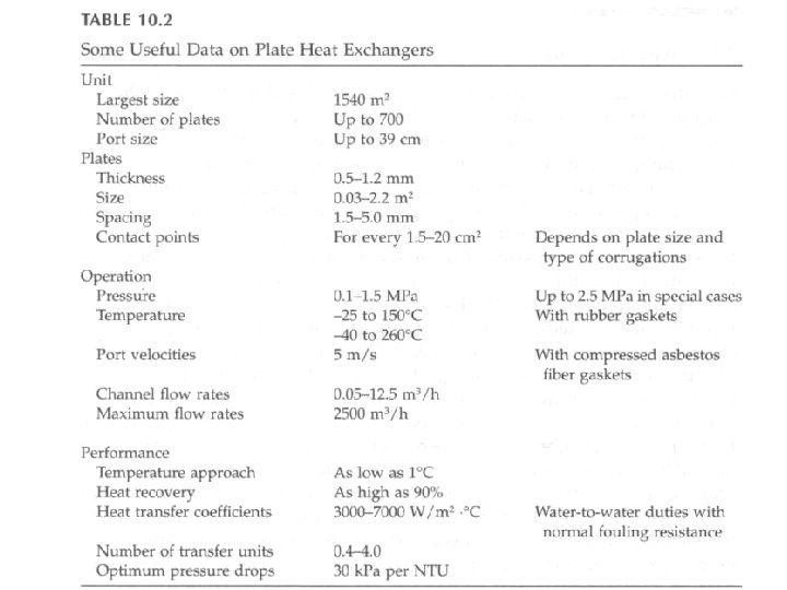
Mechanical Features Plate Pack and Frame (continued) • Plate: A sheet of metal precision-pressed into a corrugated pattern – Largest single plate: ~4. 3 m high x 1. 1 m wide – Heat transfer area for a single plate: 0. 01 – 3. 60 m 2 – To avoid poor distribution of fluid across the plate width, minimum length/width ratio: ~1. 8 – Plate thickness: 0. 5 – 1. 2 mm – Plate spacing: 2. 5 – 5. 0 mm – Hydraulic diameter: 4 – 10 mm • Leakage prevented by gaskets • Common plate materials are stainless steel, titanium; see Table 10. 1 for others and respective thermal conductivities (wrong unit in table) • Plate number and size determined by: flow rate, fluid properties, pressure drop, and temperature requirements
Mechanical Features Plate Types • Various corrugation types are available • Chevron type is most common, but also washboard pattern • Prediction methods rely on experimental data • Washboard: promotes turbulence by continuously changing flow direction and velocity • Chevron: flow channel provides swirling motion to the fluids – Chevron angle, , 25 o – 65 o range, is reversed on adjacent plates so that corrugations provide numerous contact points when plates are pressed together – Chevron angle determines pressure drop and heat transfer characteristics of the plate – Plates can be very thin, ~0. 6 mm
Plate Types and Chevron Angle
Typical Chevron Plates
Chevron Plate
Operational Characteristics Gasketed-plate HEX can be opened for inspection, cleaning, maintenance, or rebuilding within the length of the frame.
Operational Characteristics Main Advantages • Gasket design minimizes internal leakage risk. External leakage is easily detected. • Flexible design through a variety of plate sizes and pass arrangements • HT area easily accessible → change configuration to suit different process requirements by changing number of plates • Efficient HT: High HT coefficients for both fluids due to turbulence and small hydraulic diameter • Compact (large HT area/volume ratio), low weight; ~1500 m 2 surface area in one unit • Heat losses are negligible, no insulation required • If gaskets fail, intermixing of fluids cannot occur • Low fouling due to high turbulence and low residence time
Operational Characteristics Main Advantages (continued) • More than two fluids in one unit possible, by using connecting plates • Transition to turbulence occurs at low Re, 10 – 400 • Due to thin walls, wall resistance minimized • About 82% of theoretical LMTD is utilized • Similar cost with tubular HEX, if tubes are made of costly material like stainless steel • Lower costs for handling, transportation, and foundations, as well as cleaning.
Operational Characteristics Performance Limits • Gaskets impose restrictions – Operating temperatures (160 o. C – 250 o. C) – Pressures (minimum 25 – 30 bar) – Nature of fluids • Friction factors are high but channel lengths are short and flow velocities are low so pressure drops can be kept within limits for single-phase flow applications • Upper limit on the plate size due to available presses, thus largest units ~1500 m 2 • Maximum design pressure ~1 MPa • Not suitable for air-to-air or gas-to-gas applications • Not suitable for high viscosity fluids • Velocities lower than 0. 1 m/s not used • Only specially-designed units for evaporation/condensation
Passes and Flow Arrangements • Pass: group of channels in which the flow is in the same direction U: All four ports are on the fixed-head plate, permits disassembly without disturbing external piping. Flow distribution less uniform than Zarrangement. (single pass)
Passes and Flow Arrangements 2 x 3 / 2 x 3 configuration (two-pass configuration with 3 channels), counterflow except in the central plate (parallel flow) 2 x 4 / 2 x 4 configuration (two-pass configuration with 4 channels), counterflow except in the central plate (parallel flow)
Passes and Flow Arrangements 2 x 4 / 1 x 8 configuration (two-pass / one-pass flow system), one half of HEX in counterflow, the other half is in parallel flow (asymmetrical system). Used when one fluid has a much higher mass flow rate or smaller allowable pressure drop.
Passes and Flow Arrangements • Multipass arrangements require ports on both fixed and movable head plates • Usually symmetric conditions prevail (same number of passes and number of channels per pass for both fluids • Maldistribution may be a problem, must be considered in design
Applications • Widely used in chemical, pharmaceutical, food, dairy industries, hygiene products, biochemical processing; due to ease of cleaning • Also used as process heaters/coolers • Mostly liquid-to-liquid turbulent flow • Corrosion and fouling problems in large systems can be transferred to plate HEX
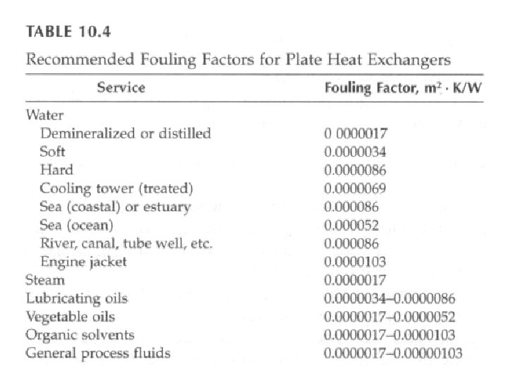
Applications Corrosion and Fouling • Highly preferred to resist corrosion, but expensive materials • Corrosion allowance is much smaller than that for tubular units • High turbulence may result in erosion problems • Less fouling than tubular units – – – High turbulence maintains solids in suspension Uniform velocity profiles and no low-velocity zones Plate surfaces are smooth Corrosion product deposits, to which fouling can adhere, are absent High heat transfer coefficients keep wall temperatures low, thus crystallization is minimized – Frequent cleaning can be easily scheduled • Assuming a pressure drop of about 30 k. Pa per NTU, Table 10. 4 lists recommended fouling factors • In general, 5% excess NTU for low fouling duties, 10% for moderate fouling, 15 -20% for high fouling