
UNITVI Heat Exchangers Heat exchanger is an equipment





- Slides: 89
UNIT-VI
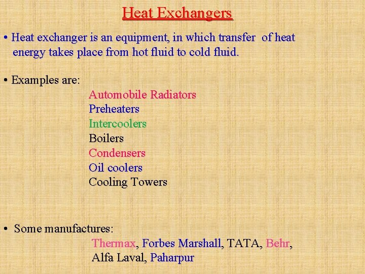
Heat Exchangers • Heat exchanger is an equipment, in which transfer of heat energy takes place from hot fluid to cold fluid. • Examples are: Automobile Radiators Preheaters Intercoolers Boilers Condensers Oil coolers Cooling Towers • Some manufactures: Thermax, Forbes Marshall, TATA, Behr, Alfa Laval, Paharpur
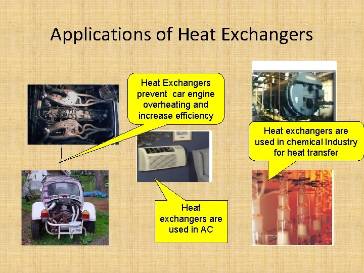
Applications of Heat Exchangers prevent car engine overheating and increase efficiency Heat exchangers are used in chemical Industry for heat transfer Heat exchangers are used in AC
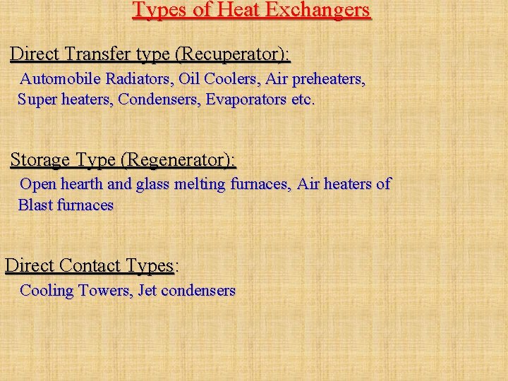
Types of Heat Exchangers Direct Transfer type (Recuperator): Automobile Radiators, Oil Coolers, Air preheaters, Super heaters, Condensers, Evaporators etc. Storage Type (Regenerator): Open hearth and glass melting furnaces, Air heaters of Blast furnaces Direct Contact Types: Cooling Towers, Jet condensers
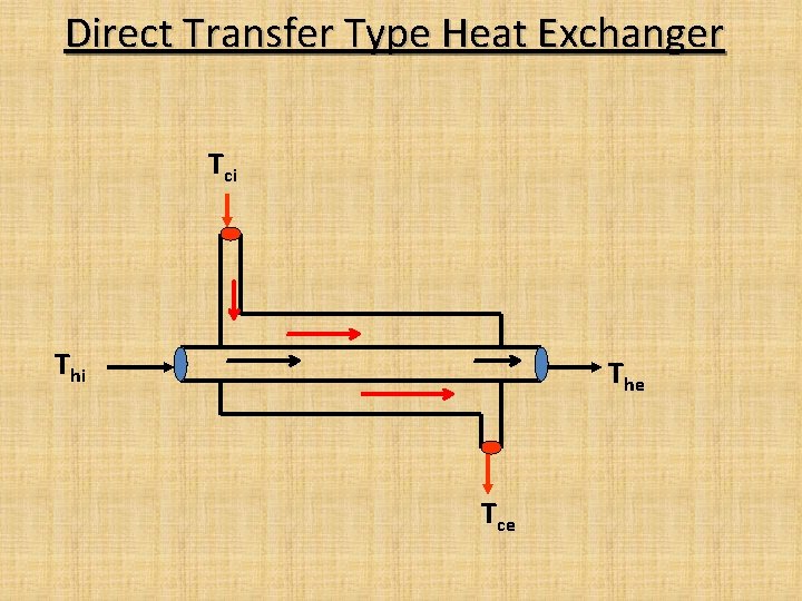
Direct Transfer Type Heat Exchanger Tci The Tce
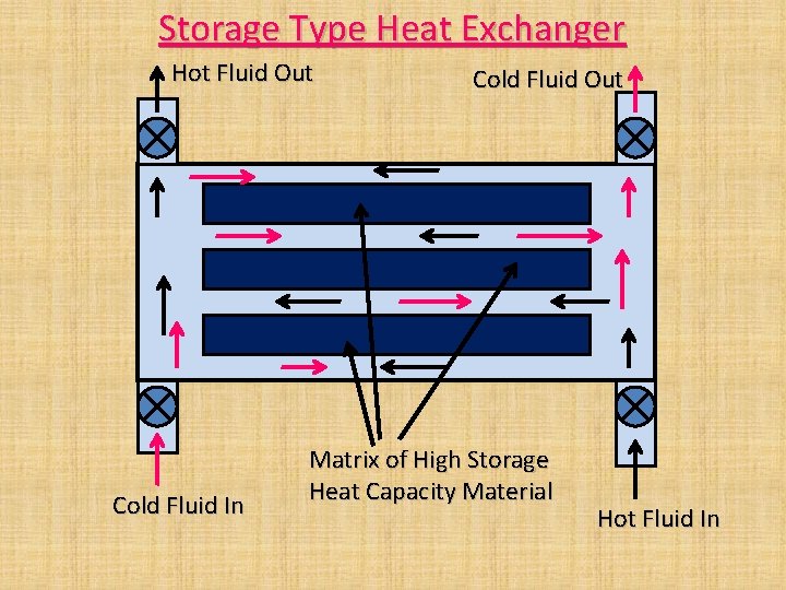
Storage Type Heat Exchanger Hot Fluid Out Cold Fluid In Cold Fluid Out Matrix of High Storage Heat Capacity Material Hot Fluid In
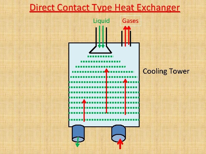
Direct Contact Type Heat Exchanger Liquid Gases Cooling Tower
Direct Transfer Type Heat Exchangers
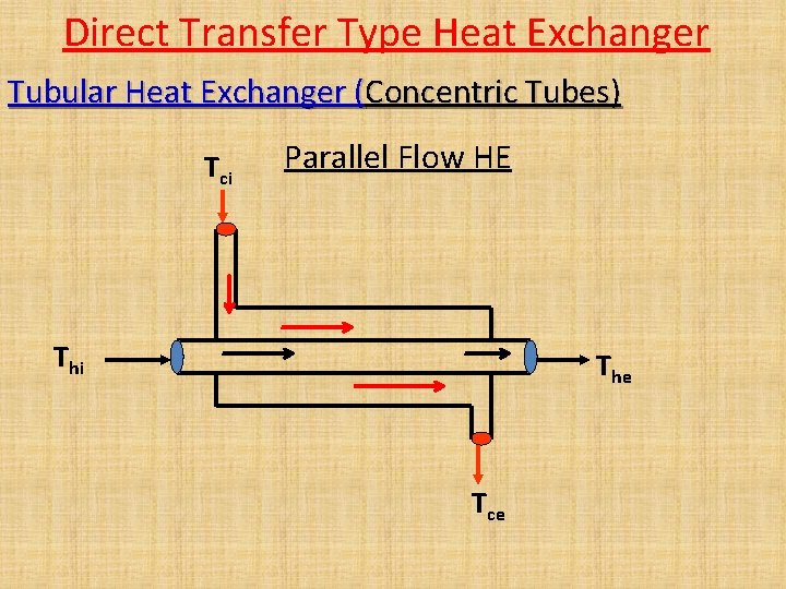
Direct Transfer Type Heat Exchanger Tubular Heat Exchanger (Concentric Tubes) Tci Parallel Flow HE Thi The Tce
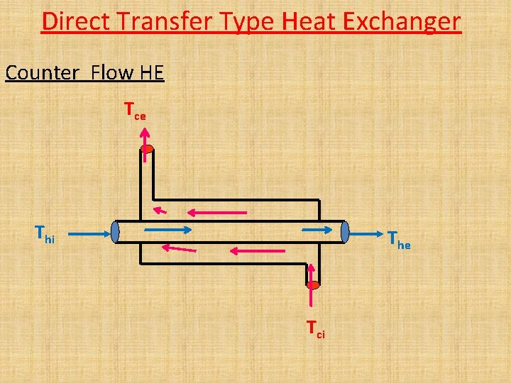
Direct Transfer Type Heat Exchanger Counter Flow HE Tce Thi The Tci
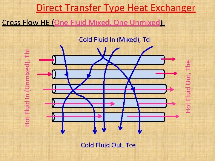
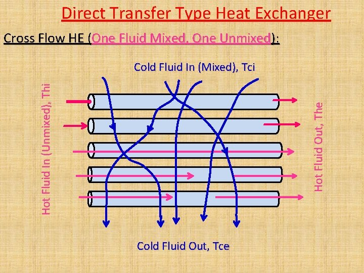
Direct Transfer Type Heat Exchanger Cross Flow HE (One Fluid Mixed, One Unmixed): Hot Fluid Out, The Hot Fluid In (Unmixed), Thi Cold Fluid In (Mixed), Tci Cold Fluid Out, Tce
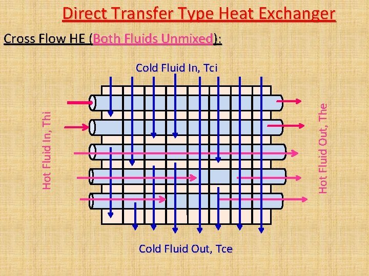
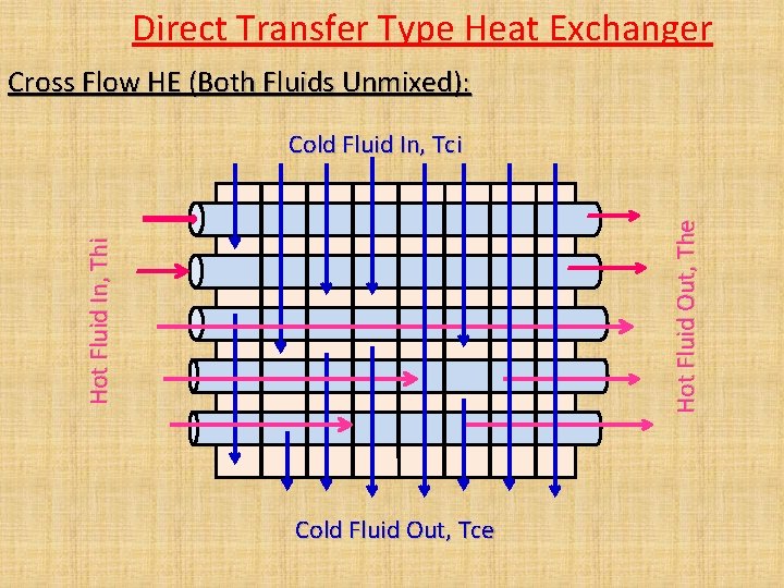
Direct Transfer Type Heat Exchanger Cross Flow HE (Both Fluids Unmixed): Hot Fluid In, Thi Hot Fluid Out, The Cold Fluid In, Tci Cold Fluid Out, Tce
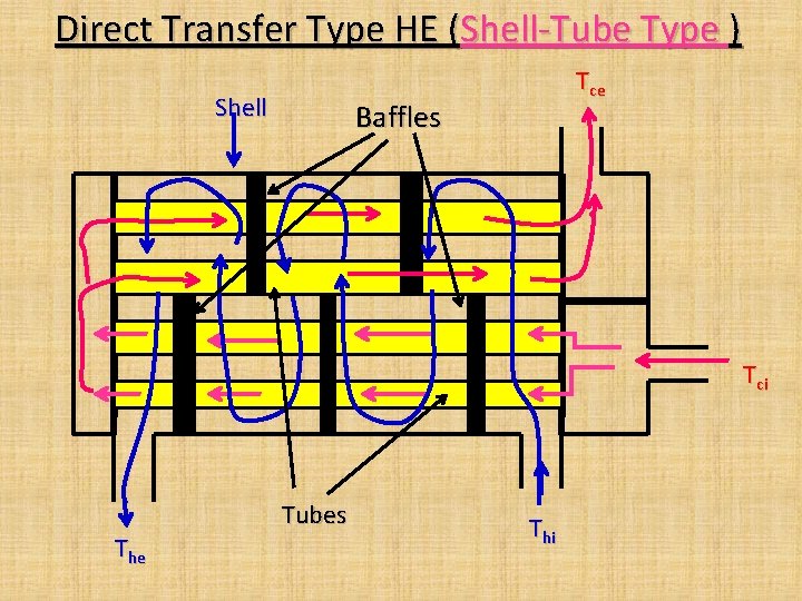
Direct Transfer Type HE (Shell-Tube Type ) Shell Tce Baffles Tci The Tubes Thi
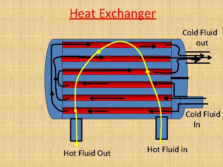
Heat Exchanger Cold Fluid out Cold Fluid In Hot Fluid Out Hot Fluid in
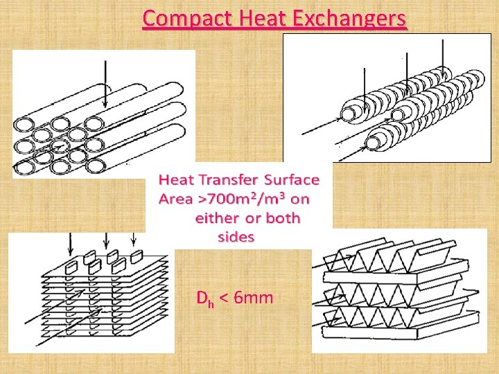
Compact Heat Exchangers Dh < 6 mm
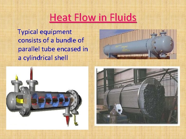
Heat Flow in Fluids Typical equipment consists of a bundle of parallel tube encased in a cylindrical shell
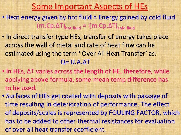
Some Important Aspects of HEs • Heat energy given by hot fluid = Energy gained by cold fluid (m. Cp. ΔT)hot fluid = (m. Cp. ΔT)cold fluid • In direct transfer type HEs, transfer of energy takes place across the wall of metal and rate of heat flow can be estimated using the term ‘ Over All Heat Transfer’ as: Q= U. A. ΔT • In HEs, ΔT varies across the length of HE, therefore, while applying above formula, some mean temp difference has to be used. • Surfaces of HEs get coated with deposits with passage of time resulting in deterioration of performance. The effect of deposits/scales is represented by FOULING FACTOR, which has to be added to othermal resistances for evaluation of over all heat transfer coefficient.
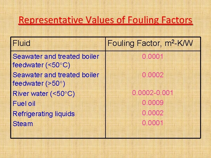
Representative Values of Fouling Factors Fluid Seawater and treated boiler feedwater (<50 C) Seawater and treated boiler feedwater (>50 ) River water (<50 C) Fuel oil Refrigerating liquids Steam Fouling Factor, m 2 -K/W 0. 0001 0. 0002 -0. 001 0. 0009 0. 0002 0. 0001
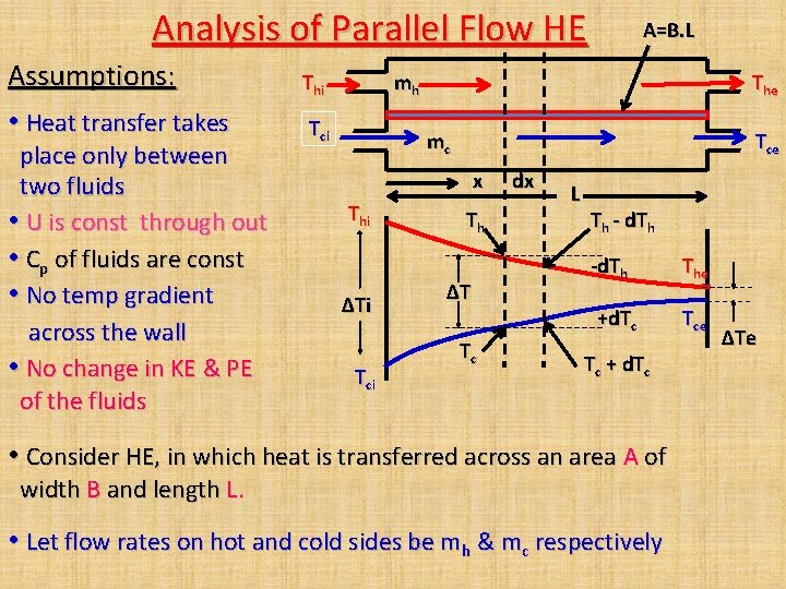
Analysis of Parallel Flow HE Assumptions: • Heat transfer takes place only between two fluids • U is const through out • Cp of fluids are const • No temp gradient across the wall • No change in KE & PE of the fluids Thi A=B. L mh Tci The mc Tce x Thi ΔTi Tci Th ΔT Tc dx L Th - d. Th -d. Th The +d. Tc Tce Tc + d. Tc • Consider HE, in which heat is transferred across an area A of width B and length L. • Let flow rates on hot and cold sides be mh & mc respectively ΔTe
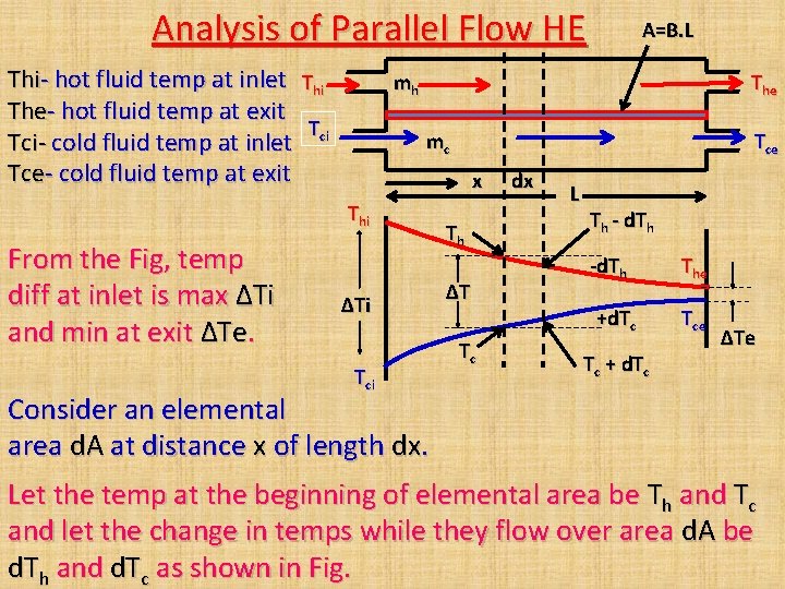
Analysis of Parallel Flow HE Thi- hot fluid temp at inlet Thi The- hot fluid temp at exit T Tci- cold fluid temp at inlet ci Tce- cold fluid temp at exit mh The mc Tce x Thi From the Fig, temp diff at inlet is max ΔTi and min at exit ΔTe. A=B. L ΔTi Tci Th ΔT Tc dx L Th - d. Th -d. Th The +d. Tc Tce Tc + d. Tc ΔTe Consider an elemental area d. A at distance x of length dx. Let the temp at the beginning of elemental area be Th and Tc and let the change in temps while they flow over area d. A be d. Th and d. Tc as shown in Fig.
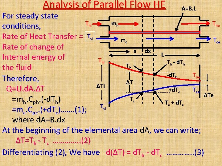
Analysis of Parallel Flow HE A=B. L For steady state Thi mh The conditions, Rate of Heat Transfer = Tci mc Tce Rate of change of x dx L Internal energy of Thi Th - d. Th T h the fluid -d. Th Therefore, ΔT ΔTi Q=U. d. A. ΔT +d. Tc Tce ΔTe Tc =mh. Cph. (-d. Th) Tc + d. Tc Tci =mc. Cpc. (+d. Tc)……. (1); where d. A=B. dx At the beginning of the elemental area d. A, we can write; ΔT=Th - Tc …………. . (2) Differentiating (2), We have d(ΔT) = d. Th - d. Tc …………. . (3)
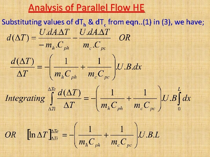
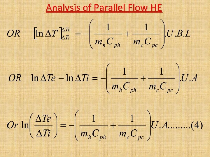
Analysis of Parallel Flow HE Substituting values of d. Th & d. Tc from eqn. . (1) in (3), we have;
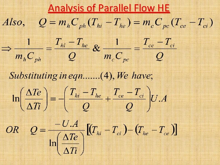
Analysis of Parallel Flow HE
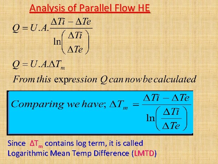
Analysis of Parallel Flow HE
Analysis of Parallel Flow HE Since ΔTm contains log term, it is called Logarithmic Mean Temp Difference (LMTD)
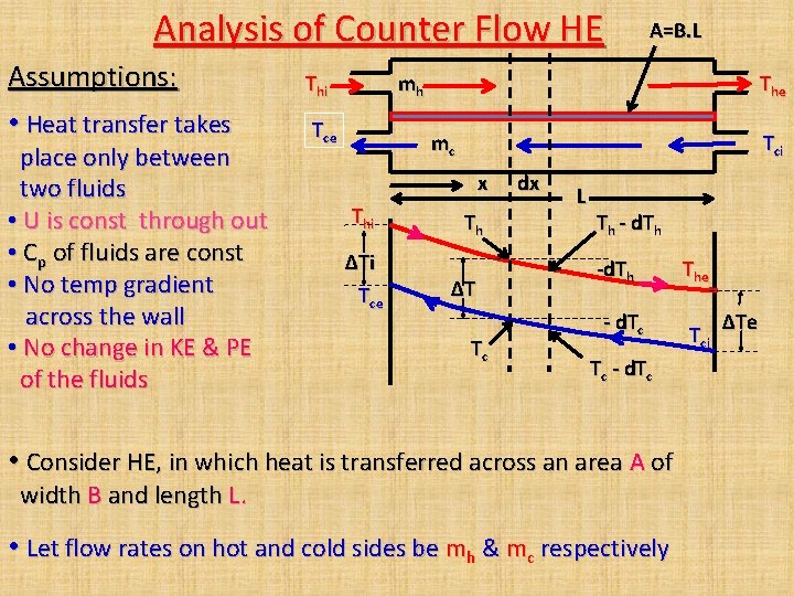
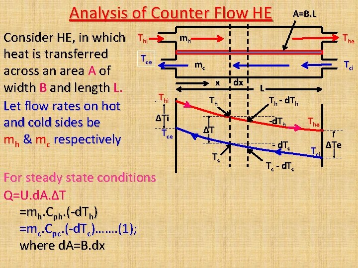
Analysis of Counter Flow HE Assumptions: • Heat transfer takes place only between two fluids • U is const through out • Cp of fluids are const • No temp gradient across the wall • No change in KE & PE of the fluids Thi A=B. L mh Tce The mc Tci x Thi ΔTi Tce Th ΔT Tc dx L Th - d. Tc Tc - d. Tc • Consider HE, in which heat is transferred across an area A of width B and length L. • Let flow rates on hot and cold sides be mh & mc respectively The Tci ΔTe
Analysis of Counter Flow HE Consider HE, in which heat is transferred across an area A of width B and length L. Let flow rates on hot and cold sides be mh & mc respectively Thi A=B. L mh Tce The mc Tci x Thi ΔTi Tce Th ΔT Tc For steady state conditions Q=U. d. A. ΔT =mh. Cph. (-d. Th) =mc. Cpc. (-d. Tc)……. (1); where d. A=B. dx dx L Th - d. Tc Tc - d. Tc The Tci ΔTe
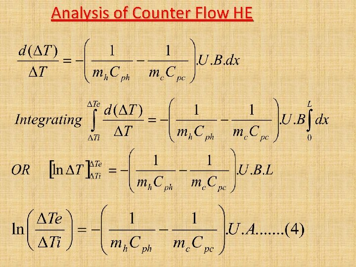
Analysis of Counter Flow HE
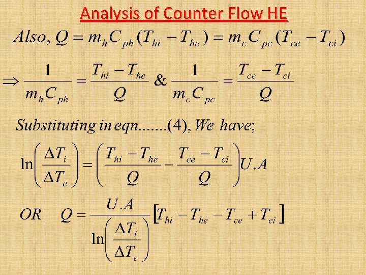
Analysis of Counter Flow HE
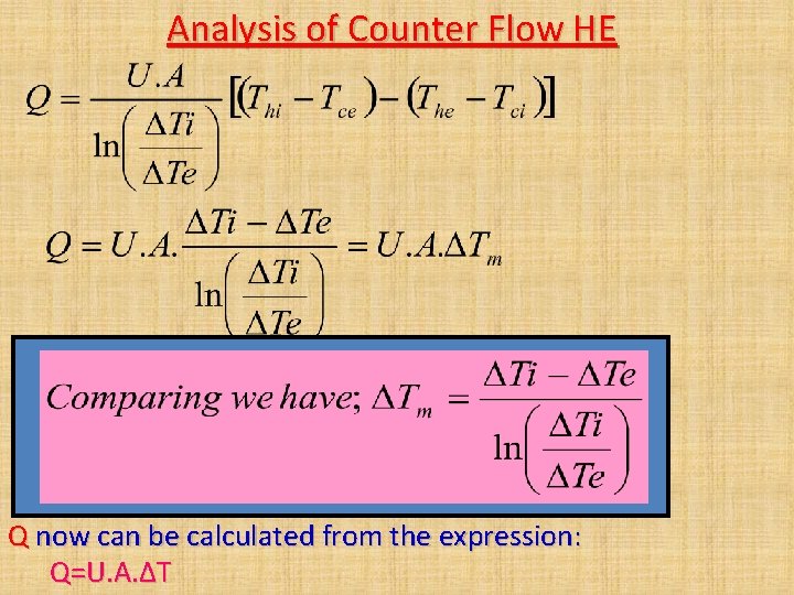
Analysis of Counter Flow HE Q now can be calculated from the expression: Q=U. A. ΔT
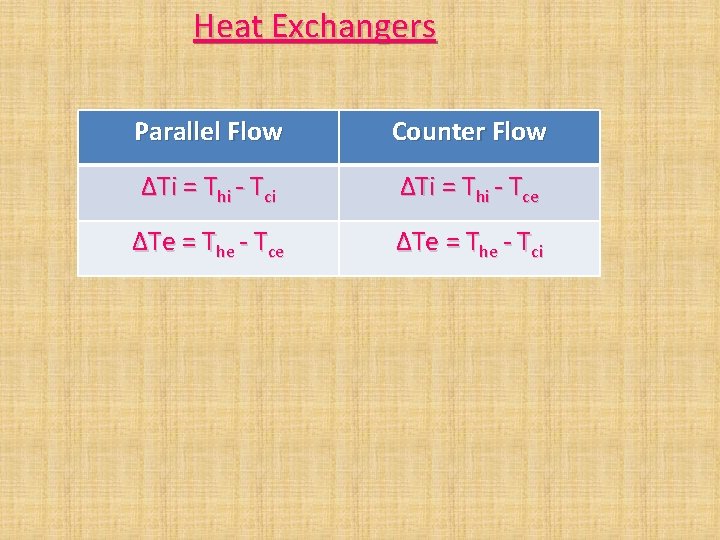
Heat Exchangers Parallel Flow Counter Flow ΔTi = Thi - Tci ΔTi = Thi - Tce ΔTe = The - Tci
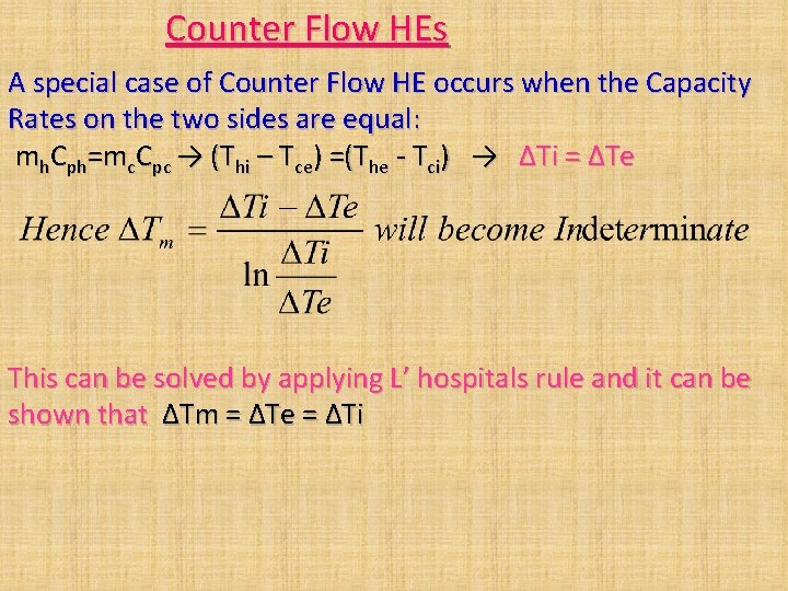
Counter Flow HEs A special case of Counter Flow HE occurs when the Capacity Rates on the two sides are equal: mh. Cph=mc. Cpc → (Thi – Tce) =(The - Tci) → ΔTi = ΔTe This can be solved by applying L’ hospitals rule and it can be shown that ΔTm = ΔTe = ΔTi
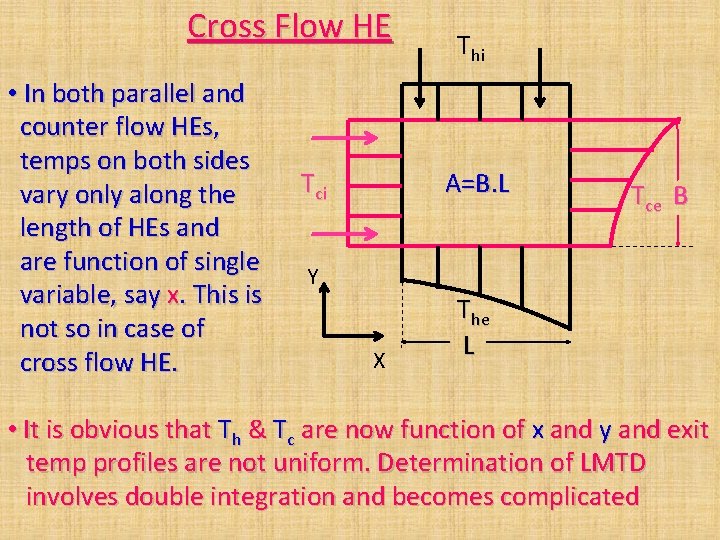
Cross Flow HE • In both parallel and counter flow HEs, temps on both sides vary only along the length of HEs and are function of single variable, say x. This is not so in case of cross flow HE. Tci Thi A=B. L Tce B Y X The L • It is obvious that Th & Tc are now function of x and y and exit temp profiles are not uniform. Determination of LMTD involves double integration and becomes complicated
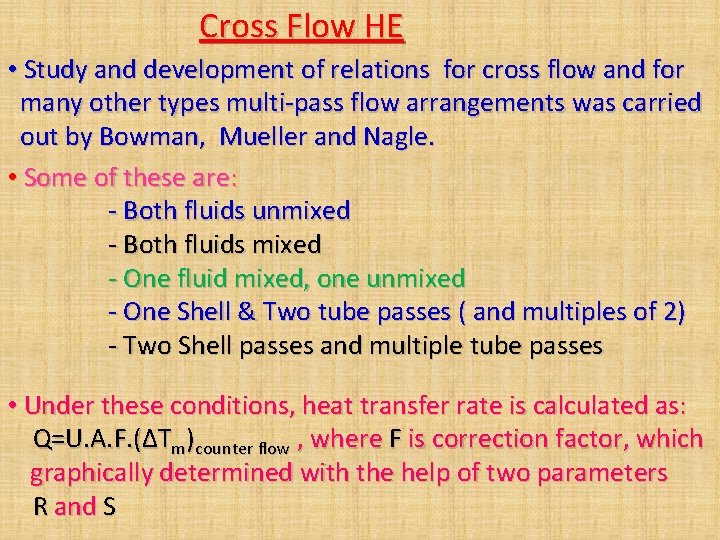
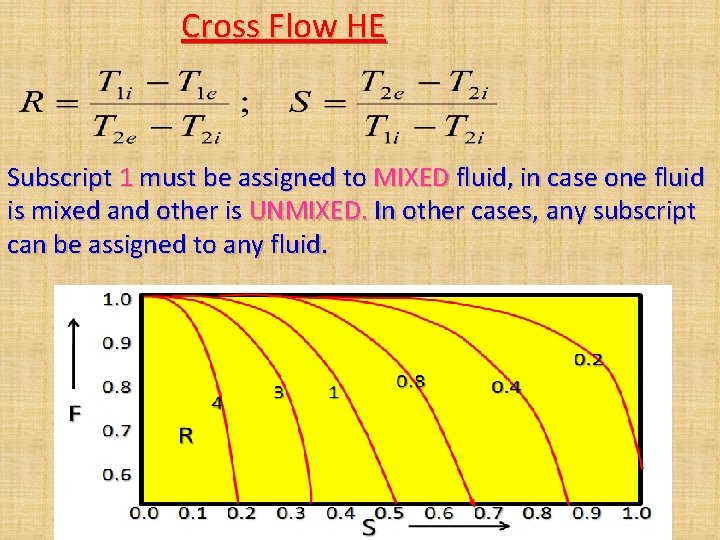
Cross Flow HE • Study and development of relations for cross flow and for many other types multi-pass flow arrangements was carried out by Bowman, Mueller and Nagle. • Some of these are: - Both fluids unmixed - Both fluids mixed - One fluid mixed, one unmixed - One Shell & Two tube passes ( and multiples of 2) - Two Shell passes and multiple tube passes • Under these conditions, heat transfer rate is calculated as: Q=U. A. F. (ΔTm)counter flow , where F is correction factor, which graphically determined with the help of two parameters R and S
Direct Transfer Type Heat Exchanger Cross Flow HE (One Fluid Mixed, One Unmixed): Hot Fluid Out, The Hot Fluid In (Unmixed), Thi Cold Fluid In (Mixed), Tci Cold Fluid Out, Tce
Direct Transfer Type Heat Exchanger Cross Flow HE (Both Fluids Unmixed): Hot Fluid In, Thi Hot Fluid Out, The Cold Fluid In, Tci Cold Fluid Out, Tce
Cross Flow HE Subscript 1 must be assigned to MIXED fluid, in case one fluid is mixed and other is UNMIXED. In other cases, any subscript can be assigned to any fluid.
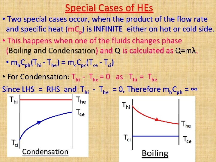
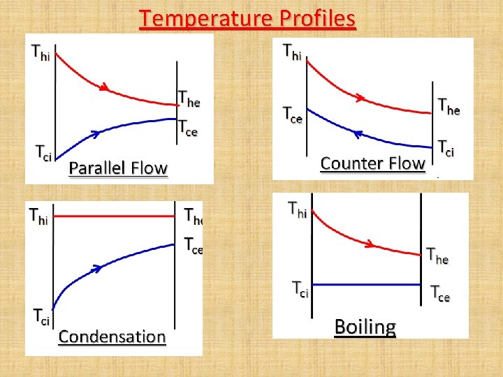
Special Cases of HEs • Two special cases occur, when the product of the flow rate and specific heat (m. Cp) is INFINITE either on hot or cold side. • This happens when one of the fluids changes phase (Boiling and Condensation) and Q is calculated as Q=mλ. • mh. Cph(Thi - The) = mc. Cpc(Tce - Tci) • For Condensation: Thi - The = 0 as Thi = The Since LHS = RHS and Thi - The = 0, Therefore mh. Cph = ∞
Temperature Profiles
NTU-Effectiveness Method • While designing and testing, two types of problems are required to be tackled: 1. For the two given fluids, mass flow rates and inlet & exit temps are specified, and size of HE is required to designed for specified performance. 2. For given HE, only inlet temps and mass flow rates of the two fluids are specified and exit temps are required to be found out. This type of problem is basically evaluation of performance of a given heat exchanger. • First kind of problems can be solved by LMTD method but second type of problems can not be solved by LMTD method. • To solve the second type of problems, NTU-Effectiveness is used. However, first type of problems can also be solved by this method.
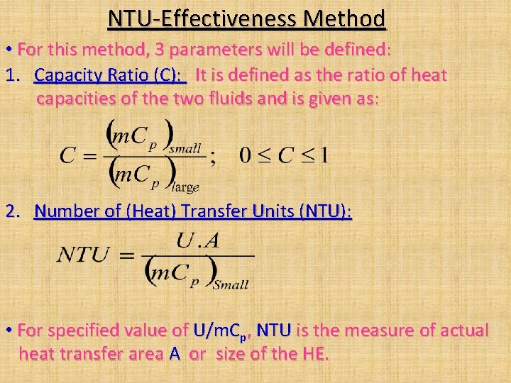
NTU-Effectiveness Method • For this method, 3 parameters will be defined: 1. Capacity Ratio (C): It is defined as the ratio of heat capacities of the two fluids and is given as: 2. Number of (Heat) Transfer Units (NTU): • For specified value of U/m. Cp, NTU is the measure of actual heat transfer area A or size of the HE.
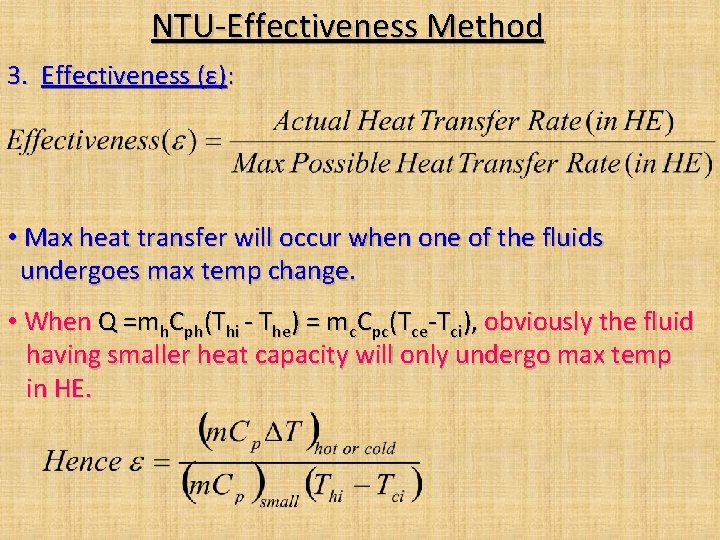
NTU-Effectiveness Method 3. Effectiveness (ε): • Max heat transfer will occur when one of the fluids undergoes max temp change. • When Q =mh. Cph(Thi - The) = mc. Cpc(Tce-Tci), obviously the fluid having smaller heat capacity will only undergo max temp in HE.
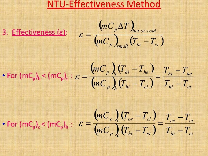
NTU-Effectiveness Method 3. Effectiveness (ε): • For (m. Cp)h < (m. Cp)c : • For (m. Cp)c < (m. Cp)h :
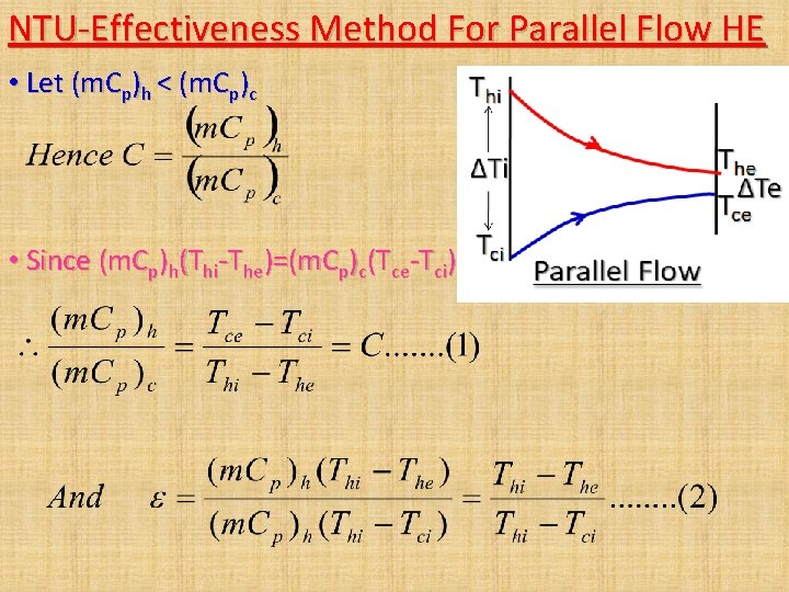
NTU-Effectiveness Method For Parallel Flow HE • Let (m. Cp)h < (m. Cp)c • Since (m. Cp)h(Thi-The)=(m. Cp)c(Tce-Tci)
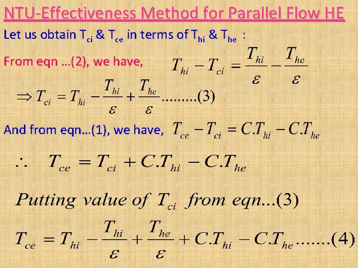
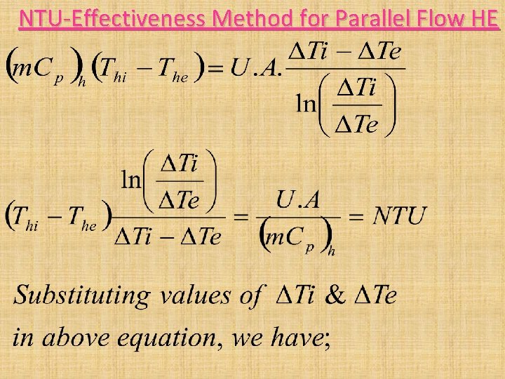
NTU-Effectiveness Method for Parallel Flow HE Let us obtain Tci & Tce in terms of Thi & The : From eqn …(2), we have, And from eqn…(1), we have,
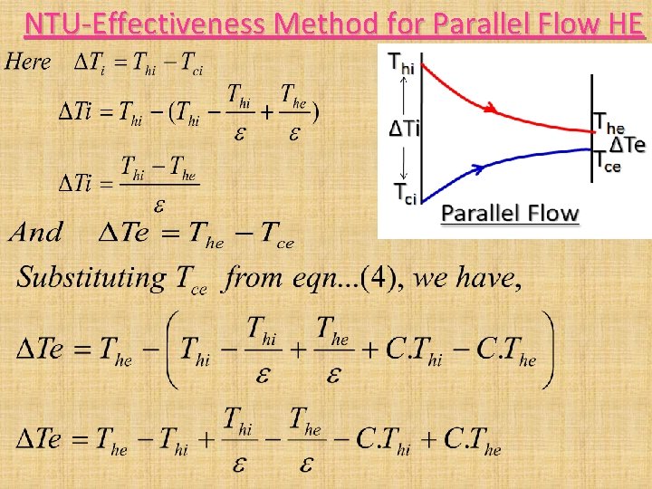
NTU-Effectiveness Method for Parallel Flow HE
NTU-Effectiveness Method for Parallel Flow HE
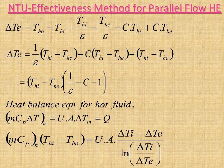
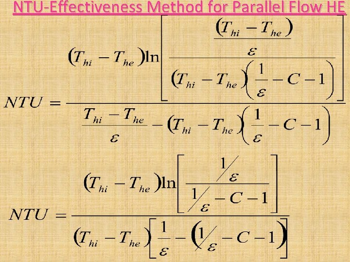
NTU-Effectiveness Method for Parallel Flow HE
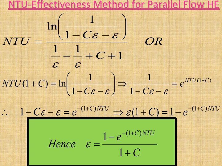
NTU-Effectiveness Method for Parallel Flow HE
NTU-Effectiveness Method for Parallel Flow HE
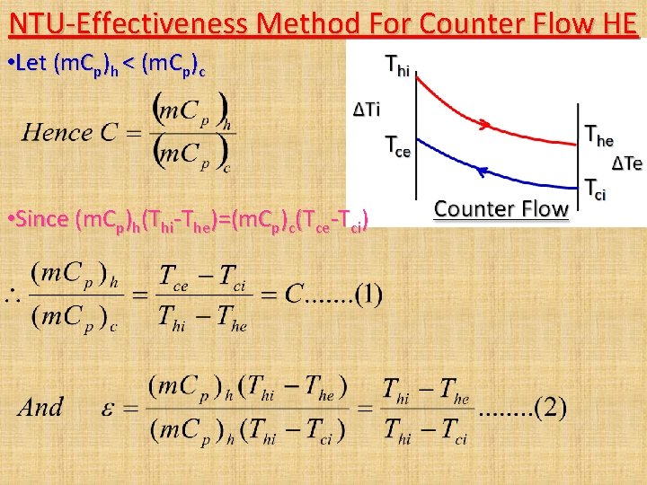
NTU-Effectiveness Method For Counter Flow HE • Let (m. Cp)h < (m. Cp)c • Since (m. Cp)h(Thi-The)=(m. Cp)c(Tce-Tci)
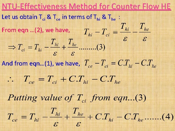
NTU-Effectiveness Method for Counter Flow HE Let us obtain Tci & Tce in terms of Thi & The : From eqn …(2), we have, And from eqn…(1), we have,
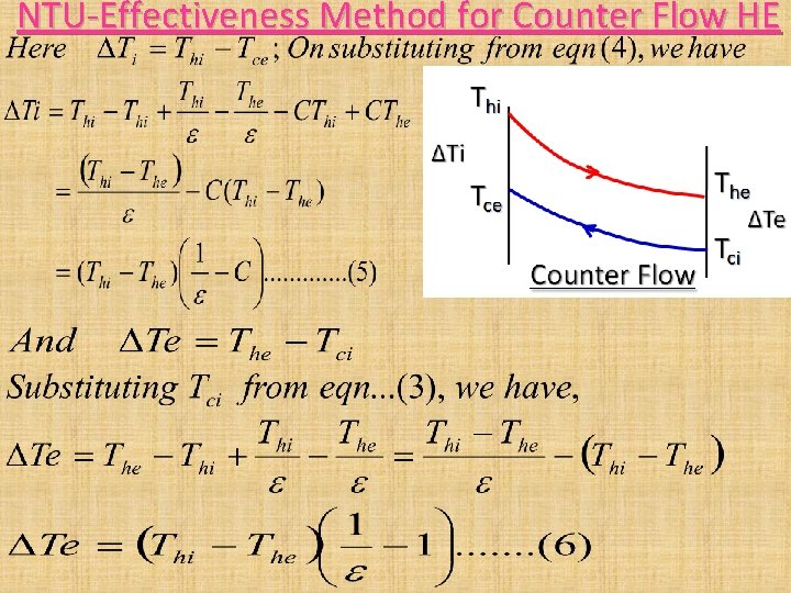
NTU-Effectiveness Method for Counter Flow HE
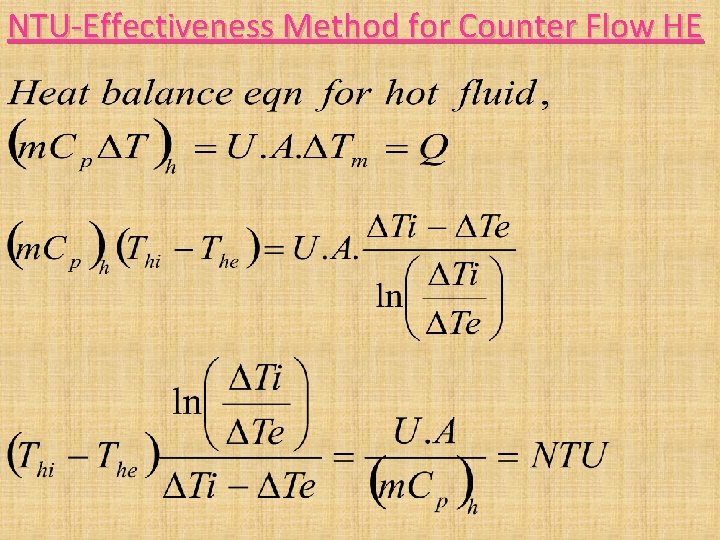
NTU-Effectiveness Method for Counter Flow HE
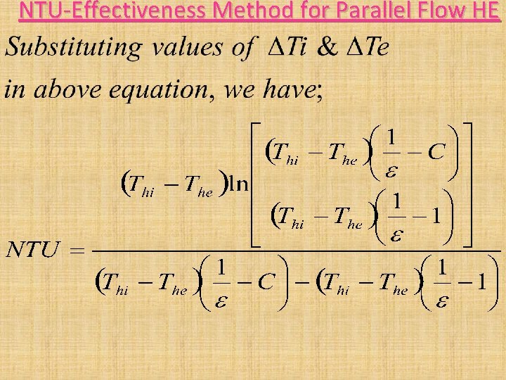
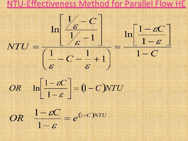
NTU-Effectiveness Method for Parallel Flow HE
NTU-Effectiveness Method for Parallel Flow HE
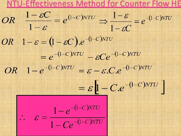
NTU-Effectiveness Method for Counter Flow HE
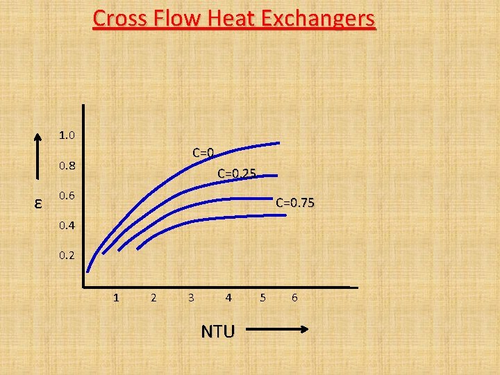
Cross Flow Heat Exchangers 1. 0 C=0 0. 8 ε C=0. 25 0. 6 C=0. 75 0. 4 0. 2 1 2 3 4 NTU 5 6
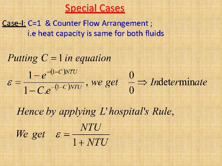
Special Cases Case-I: C=1 & Counter Flow Arrangement ; i. e heat capacity is same for both fluids
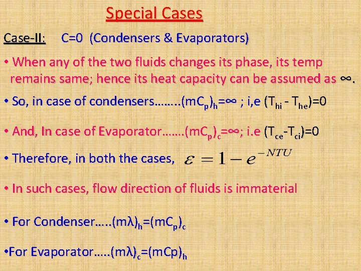
Special Cases Case-II: C=0 (Condensers & Evaporators) • When any of the two fluids changes its phase, its temp remains same; hence its heat capacity can be assumed as ∞. • So, in case of condensers……. . (m. Cp)h=∞ ; i, e (Thi - The)=0 • And, In case of Evaporator……. (m. Cp)c=∞; i. e (Tce-Tci)=0 • Therefore, in both the cases, • In such cases, flow direction of fluids is immaterial • For Condenser…. . (mλ)h=(m. Cp)c • For Evaporator…. . (mλ)c=(m. Cp)h
Numerical Problems on Heat Exchangers
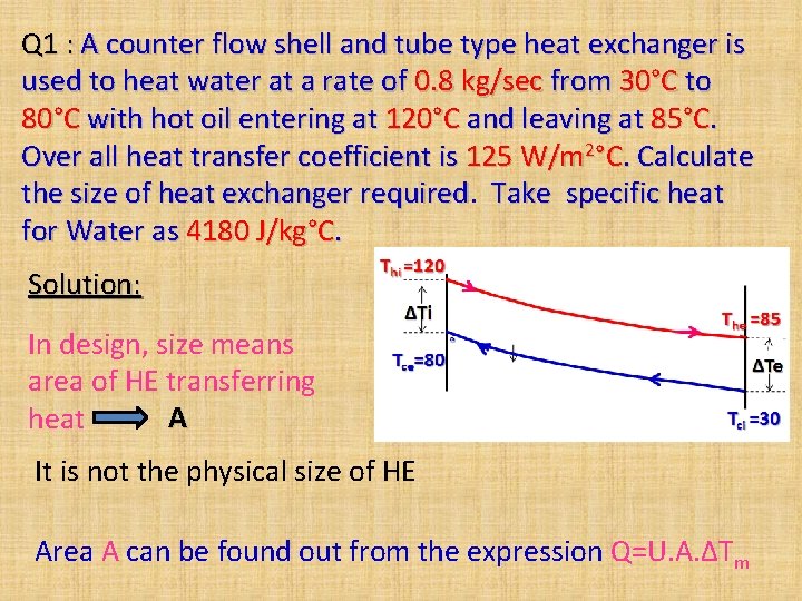
Q 1 : A counter flow shell and tube type heat exchanger is used to heat water at a rate of 0. 8 kg/sec from 30°C to 80°C with hot oil entering at 120°C and leaving at 85°C. Over all heat transfer coefficient is 125 W/m 2°C. Calculate the size of heat exchanger required Take specific heat for Water as 4180 J/kg°C. Solution: In design, size means area of HE transferring A heat It is not the physical size of HE Area A can be found out from the expression Q=U. A. ΔTm
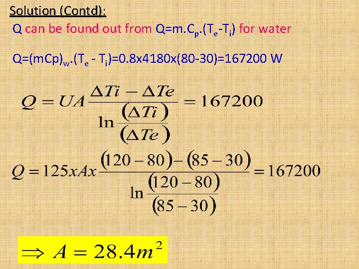
Solution (Contd): Q can be found out from Q=m. Cp. (Te-Ti) for water Q=(m. Cp)w. (Te - Ti)=0. 8 x 4180 x(80 -30)=167200 W
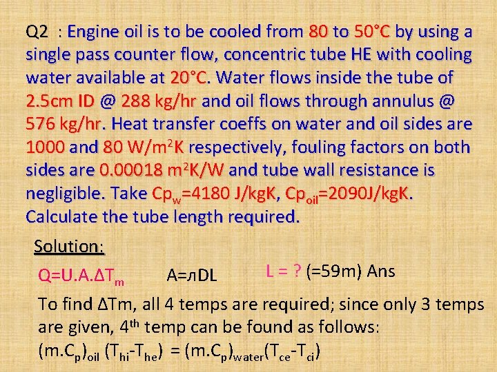
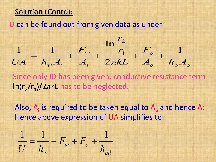
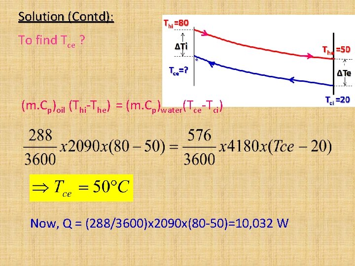
Q 2 : Engine oil is to be cooled from 80 to 50°C by using a single pass counter flow, concentric tube HE with cooling water available at 20°C. Water flows inside the tube of 2. 5 cm ID @ 288 kg/hr and oil flows through annulus @ 576 kg/hr. Heat transfer coeffs on water and oil sides are 1000 and 80 W/m 2 K respectively, fouling factors on both sides are 0. 00018 m 2 K/W and tube wall resistance is negligible. Take Cpw=4180 J/kg. K, Cpoil=2090 J/kg. K. Calculate the tube length required. Solution: L = ? (=59 m) Ans Q=U. A. ΔTm A=л. DL To find ΔTm, all 4 temps are required; since only 3 temps are given, 4 th temp can be found as follows: (m. Cp)oil (Thi-The) = (m. Cp)water(Tce-Tci)
Solution (Contd): U can be found out from given data as under: Since only ID has been given, conductive resistance term ln(r 2/r 1)/2 лk. L has to be neglected. Also, Ai is required to be taken equal to Ao and hence A; Hence above expression of UA simplifies to:
Solution (Contd): To find Tce ? (m. Cp)oil (Thi-The) = (m. Cp)water(Tce-Tci) Now, Q = (288/3600)x 2090 x(80 -50)=10, 032 W
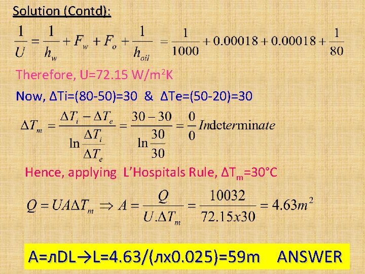
Solution (Contd): Therefore, U=72. 15 W/m 2 K Now, ΔTi=(80 -50)=30 & ΔTe=(50 -20)=30 Hence, applying L’Hospitals Rule, ΔTm=30°C A=л. DL→L=4. 63/(лx 0. 025)=59 m ANSWER
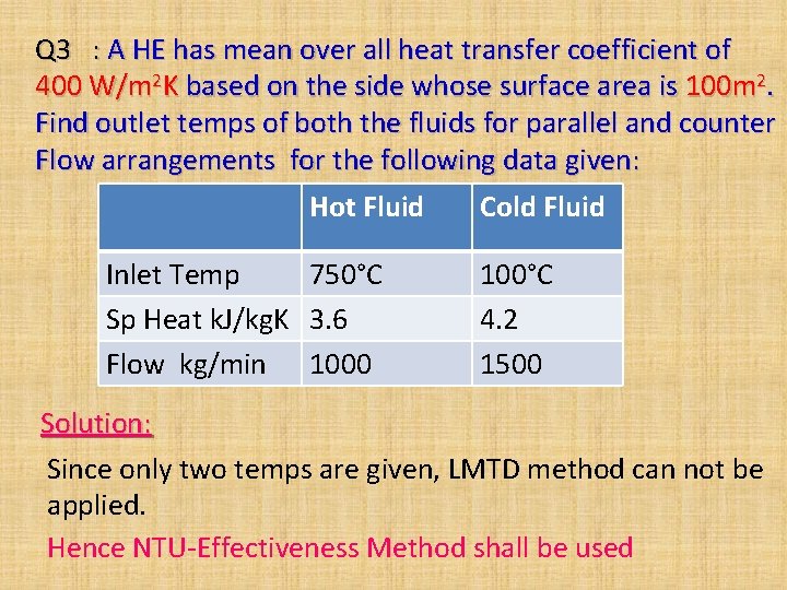
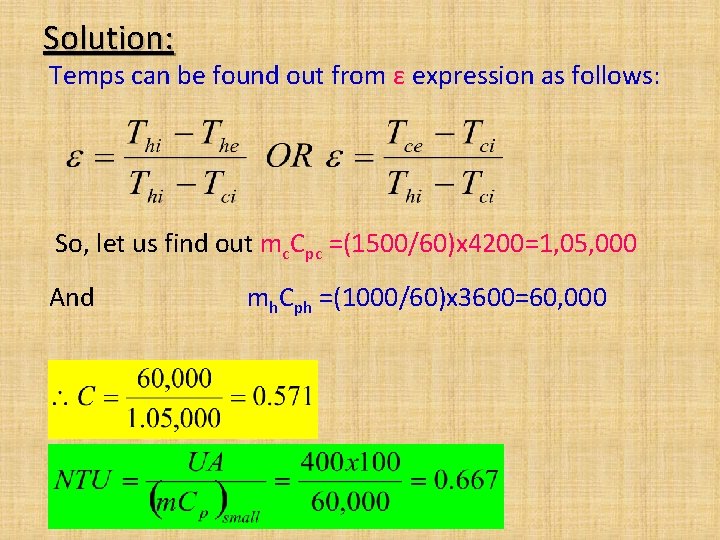
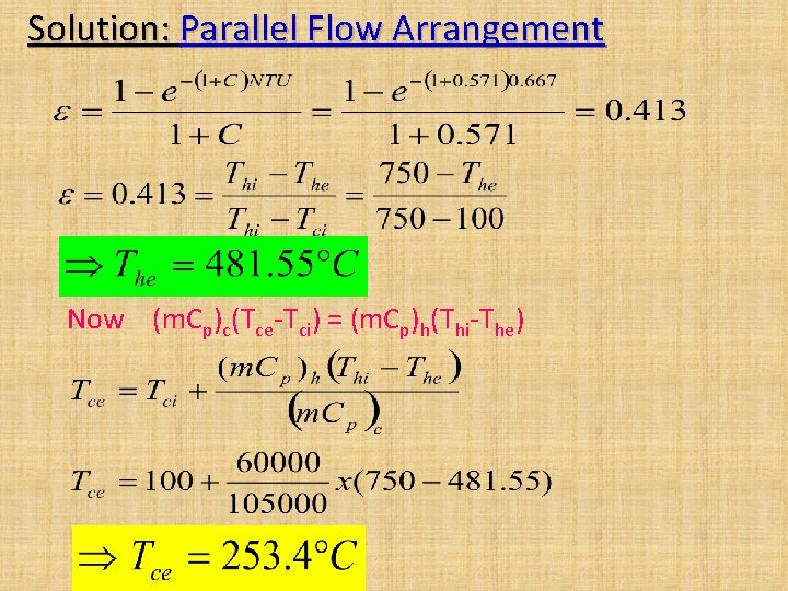
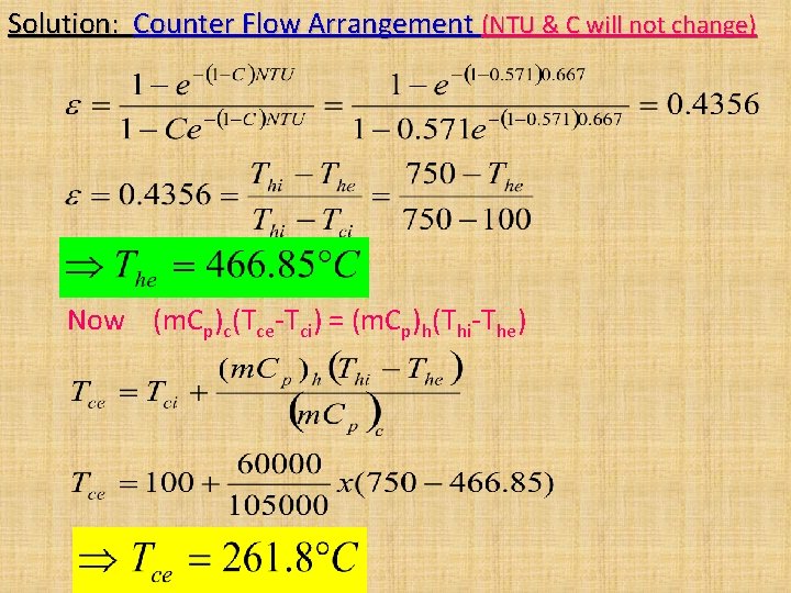
Q 3 : A HE has mean over all heat transfer coefficient of 400 W/m 2 K based on the side whose surface area is 100 m 2. Find outlet temps of both the fluids for parallel and counter Flow arrangements for the following data given: Hot Fluid Cold Fluid Inlet Temp 750°C Sp Heat k. J/kg. K 3. 6 Flow kg/min 1000 100°C 4. 2 1500 Solution: Since only two temps are given, LMTD method can not be applied. Hence NTU-Effectiveness Method shall be used
Solution: Temps can be found out from ε expression as follows: So, let us find out mc. Cpc =(1500/60)x 4200=1, 05, 000 And mh. Cph =(1000/60)x 3600=60, 000
Solution: Parallel Flow Arrangement Now (m. Cp)c(Tce-Tci) = (m. Cp)h(Thi-The)
Solution: Counter Flow Arrangement (NTU & C will not change) Now (m. Cp)c(Tce-Tci) = (m. Cp)h(Thi-The)
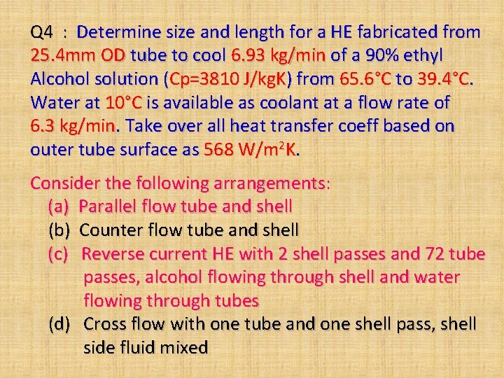
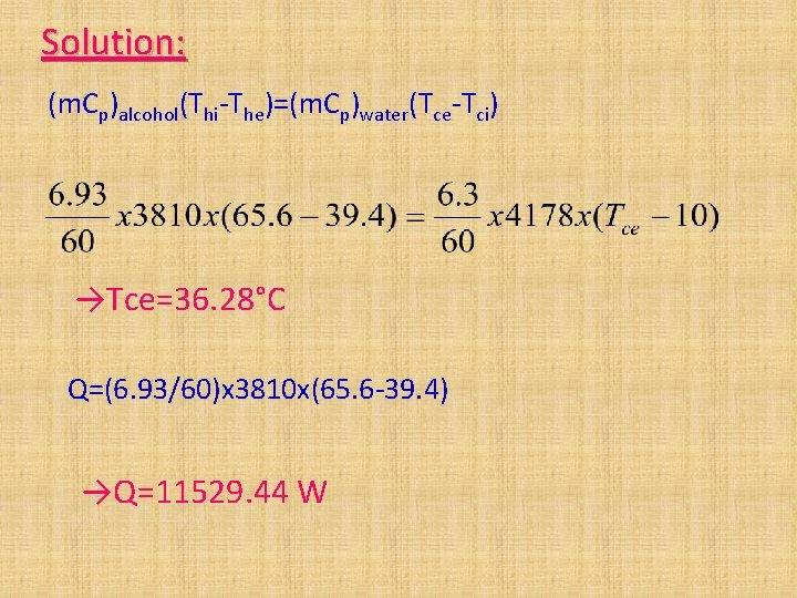
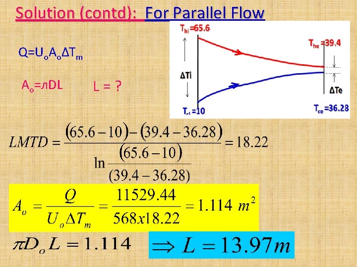
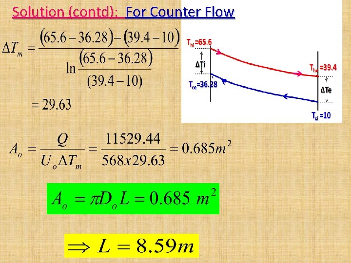
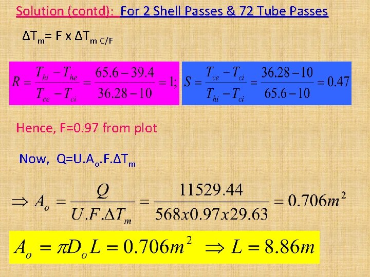
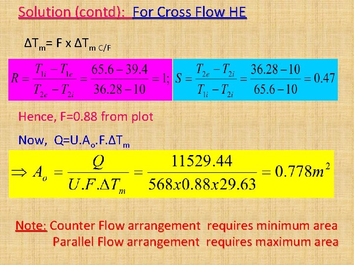
Q 4 : Determine size and length for a HE fabricated from 25. 4 mm OD tube to cool 6. 93 kg/min of a 90% ethyl Alcohol solution (Cp=3810 J/kg. K) from 65. 6°C to 39. 4°C. Water at 10°C is available as coolant at a flow rate of 6. 3 kg/min. Take over all heat transfer coeff based on outer tube surface as 568 W/m 2 K. Consider the following arrangements: (a) Parallel flow tube and shell (b) Counter flow tube and shell (c) Reverse current HE with 2 shell passes and 72 tube passes, alcohol flowing through shell and water flowing through tubes (d) Cross flow with one tube and one shell pass, shell side fluid mixed
Solution: (m. Cp)alcohol(Thi-The)=(m. Cp)water(Tce-Tci) →Tce=36. 28°C Q=(6. 93/60)x 3810 x(65. 6 -39. 4) →Q=11529. 44 W
Solution (contd): For Parallel Flow Q=Uo. AoΔTm Ao=л. DL L=?
Solution (contd): For Counter Flow
Solution (contd): For 2 Shell Passes & 72 Tube Passes ΔTm= F x ΔTm C/F Hence, F=0. 97 from plot Now, Q=U. Ao. F. ΔTm
Solution (contd): For Cross Flow HE ΔTm= F x ΔTm C/F Hence, F=0. 88 from plot Now, Q=U. Ao. F. ΔTm Note: Counter Flow arrangement requires minimum area Parallel Flow arrangement requires maximum area
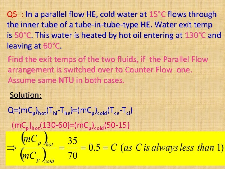
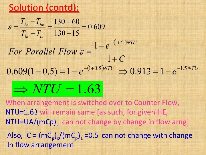
Q 5 : In a parallel flow HE, cold water at 15°C flows through the inner tube of a tube-in-tube-type HE. Water exit temp is 50°C. This water is heated by hot oil entering at 130°C and leaving at 60°C. Find the exit temps of the two fluids, if the Parallel Flow arrangement is switched over to Counter Flow one. Assume same NTU in both cases. Solution: Q=(m. Cp)hot(Thi-The)=(m. Cp)cold(Tce-Tci) (m. Cp)hot(130 -60)=(m. Cp)cold(50 -15)
Solution (contd): When arrangement is switched over to Counter Flow, NTU=1. 63 will remain same [as such, for given HE, NTU=UA/(m. Cp)s can not change by change in flow arng] Also, C = (m. Cp)s/(m. Cp)L =0. 5 can not change with change In flow arrangement
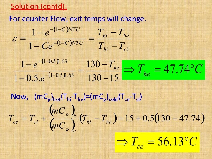
Solution (contd): For counter Flow, exit temps will change. Now, (m. Cp)hot(Thi-The)=(m. Cp)cold(Tce-Tci)
Design Aspects of HEs 1. Heat Transfer Rate Q: • Q requirement to be met • Requires selection of many parameters 2. Flow Rates: • Flow rates decide velocities of fluids • Lower velocity, lower the ‘h’ and higher velocity causes noise, vibrations, higher frictional losses & pressure drops (Generally 5 -6 m/s) 3. Fouling Factor : • Fluid properties, tendency of scale formation • Selection of HE material, expected life span, maintenance requirement
Design Aspects of HEs 4. Outer Shape & Over all Dimensions: • Space & shape of space available in main equipment • Based on above, tube length, layout etc to be decided 5. Strength Factor: • HE to be designed for high strength keeping temp, operating pressure, vibrations etc, in mind • Lowest weight and size 6. Pressur Drop & Pumping Power Requirement : • ΔP ∞ V 2 ; m ∞ V; Power ∞ m. ΔP; P∞V 3 & P∞ 1/Dh • Hence compromise reqd among Q, P & ΔP 7. Cost: • Lowest initial and maintenance /operating cost
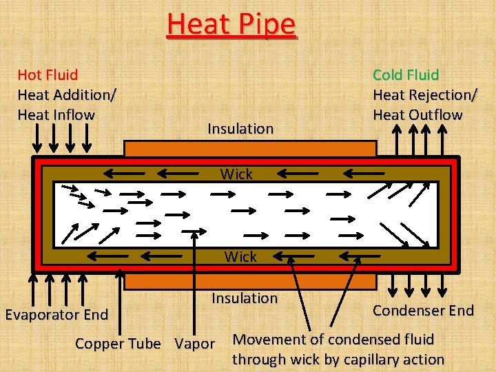
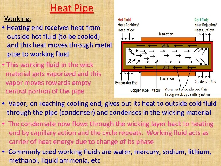
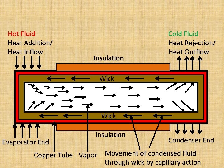
Heat Pipe Hot Fluid Heat Addition/ Heat Inflow Insulation Cold Fluid Heat Rejection/ Heat Outflow Wick Evaporator End Insulation Copper Tube Vapor Condenser End Movement of condensed fluid through wick by capillary action
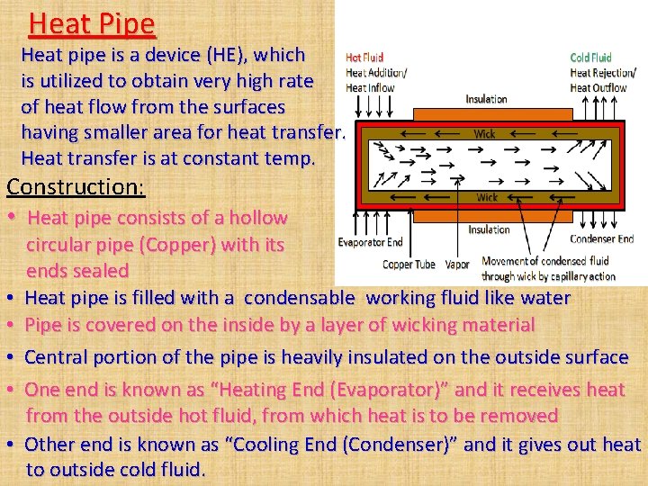
Heat Pipe Heat pipe is a device (HE), which is utilized to obtain very high rate of heat flow from the surfaces having smaller area for heat transfer. Heat transfer is at constant temp. Construction: • Heat pipe consists of a hollow • • • circular pipe (Copper) with its ends sealed Heat pipe is filled with a condensable working fluid like water Pipe is covered on the inside by a layer of wicking material Central portion of the pipe is heavily insulated on the outside surface One end is known as “Heating End (Evaporator)” and it receives heat from the outside hot fluid, from which heat is to be removed Other end is known as “Cooling End (Condenser)” and it gives out heat to outside cold fluid.
Heat Pipe Working: • Heating end receives heat from outside hot fluid (to be cooled) and this heat moves through metal pipe to working fluid • This working fluid in the wick material gets vaporized and this vapor moves towards empty central portion of the pipe • Vapor, on reaching cooling end, gives out its heat to outside cold fluid through the pipe (condenser) and condenses in the wicking material • The condensate now flows through the wicking layer back to heating end by capillary action and the cycle repeats. Working fluid acts as carrier of heat energy due to change of its phase • Commonly used working fluids are water, mercury, sodium, lithium, methanol, liquid ammonia, etc
Applications of Heat Pipe • Heating and cooling of space vehicles • Heat dissipation/removal from small micro-electronic circuits/ small electronic circuits generating large amount of heat • Temperature control device to maintain temperature of a system to desired/specified value Heat pipe of copper using water as working fluid can transport an axial heat flux of 6500 k. W/m 2 at 200°C
Heat Transfer Augmentation Techniques • Use of twisted tape • Use of internal extended surfaces • Use of dimple surface
Tutorial No 6 Assignment No 6 END OF UNIT VI
Hot Fluid Heat Addition/ Heat Inflow Insulation Cold Fluid Heat Rejection/ Heat Outflow Wick Evaporator End Insulation Copper Tube Vapor Condenser End Movement of condensed fluid through wick by capillary action