Heater Pump compressor Fired Heater Fired heater is


 • VC with convection")


 Roto-dynamic (or) dynamicpressure pumps: • Having a rotating")


- Slides: 39
Heater, Pump & compressor
Fired Heater • Fired heater is a device in which heat liberated by the combustion of a fuel within an internally insulated enclosure is transferred to fluid flowing through tubular coils. • Fundamental function of a fired heater is to supply a specified quantity of heat at elevated temperature levels to the fluid being heated
Fired Heater q. Column Reboilers q. Fractionating Column Feed Pre-heaters q. Reactor Feed Pre-heaters- CRU/DCU/HCU q. Fired Reactors Reformer) (Ethylene Crackers, H 2
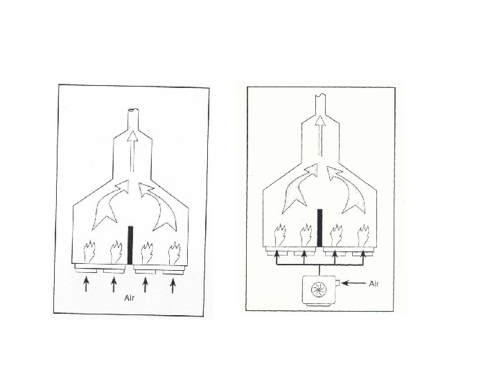
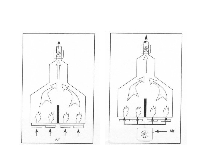
Fired Heater Operation q. Natural draft q. Forced draft q. Induced draft q. Balanced draft
Heater • Most chemical plants and all petroleum refineries contain fired heaters as a means of providing heat energy into a system. • Because the equipment utilizes an outside source of fuel it is usually supported and enhanced by a heat exchange system to minimize the quantity of fuel required. • Generally fired heaters fall into two major categories: – Horizontal type – Vertical type • The horizontal type heater usually means a box type heater with the tubes running horizontally along the walls. • Vertical type is normally a cylindrical heater containing vertical tubes.
Fired Heater Operation-Vertical Cylinder
Fired Heater Operation-Cabin
Fired Heater Operation • All-radiant VC (<2 – 3 MMkcal/hr) • VC with convection (<35 – 40 MMkcal/hr) • Cabin type (Single/twin cell) (<50 – 60 MMkcal/hr)
Heat Transfer Mechanisms • Heat is transferred in a fired heater in two modes. In both cases, heat flows from the combustion products, called the flue gas, to a heatabsorbing surface. • One heat transfer mechanism is radiant transfer and the other is convective transfer. Radiant heat transfer follows the relationship: • • Where: σ = Stefan Boltzman Constant ɛ = emissivity of the gas A = area of the plane absorbing the radiation T = temperature of the combustion products (flue gas) t = temperature of the cold plane absorbing the radiation (the tubes) Convective heat transfer follows the relationship: • • Where: U = Overall heat transfer coefficient A = Surface area of the tubes LMTD = log mean temperature difference
• • Burners The purpose of a burner is to mix fuel and air to ensure complete combustion. There about 12 basic burner designs. These are: Direction – – – • Capacity – – • normal low Atomization – – – • • • high Excess air – – • normal slant thin, fan-shaped flat adaptable pattern Hydrogen content – • gas oil combination Flame shape – – – • high low Fuel type – – – • vertical up fired vertical down fired horizontally fired steam mechanical air assisted mechanical Boiler types Low NOx High intensity Various combinations of the above types are available.
Types of burners • Gas, Oil & Combination Burners • Combination Burners will burn either gas or oil. • It is better if they are not operated to burn both fuels at the same time because the chemistry of gas combustion is different from that of oil combustion. • Gases burn by progressive oxidation and oils by cracking. • If gas and oil are burned simultaneously in the same burner, the flame volume will be twice that of either fuel alone.
Burner control • Burner controls become very important from safety and operation considerations. • Most systems include an instrumentation system with interlocks that prohibit: – Continuing firing when the process flow in the heater coil fails – The flow of fuel into the firebox on flame failure • Under normal operating conditions the amount of fuel that is burnt is controlled by flow controllers operated on the coil outlet temperature. • With combination burners the failure of one type of fuel automatically introduces the second type. • Such a switch over can also be effected manually. This aspect is usually activated on pressure control of the respective fuel system. That is, on low pressure being sensed on the fuel being fired automatically switches to the second fuel. • Most companies operate their own specific controls for the heater firing system.
Common Furnace Problems • Flame Impingement: flames from the burner touching a tube – Weakens the metal tube and causes coke (carbon) to form inside the tube where the process fluid flows – Solve by reducing the fuel supply to the affected burner
Common Furnace Problems • Coke Formation – Coking always occurs inside the process fluid tubes (typically the radiant tube section where it is hottest) in a furnace. – Remove coke by shutting down the furnace (typically once/3 yrs) and injecting superheated steam to remove the coke.
Refractories • Refractories are used on the inside walls of the heater fire box, floor and through the convection side of the heater. • The purpose of this refractory lining is to conserve the heat by limiting its loss to atmosphere by convection. • It is also necessary for personal safety of those working on or about the heater who may accidentally touch the heater walls. • Good insulation has the following qualities: – It has good high temperature strength – It is resistant to abrasion, spalling, chemical reaction, and slagging – It has good insulating properties Spall are flakes of a material that are broken Slag is fused material formed during the smelting of metals off a larger solid body
Common Furnace Problems • Replace Refractory – Refractory in the fire box becomes brittle and starts to fall off over time at high temperatures. – Solve by shutting down the furnace (typically once/3 yrs) and removing old refractory and installing new refractory.
Stack Emissions • The obnoxious compounds in stack gas emissions arise from: – Impurities in the fuel – Chemical reactions resulting from the fuel combustion with air • The three major impurities in oil or gas fuels which produce undesirable emissions are: – Sulfur – Metals – Nitrogen • • Sulfur All gas and oil fuels contain sulfur at some level of concentration. When these fuels are burned the sulfur reacts with air to form SO 2 and SO 3. These compounds are objectionable because they cause: – Air pollution in the form of smog – They contribute to the corrosion of heater tubes and stack • • Metals The most objectionable metal impurities in fuel oil are sodium and vanadium. These can cause severe corrosion of tubes and refractory lining. By high vanadium content is meant concentrations between 200 ppm and 400 ppm, above 400 ppm is considered very high and should not be used as a fuel.
Stack Emissions • Nitrogen • Some nitrogen oxides will be formed in combustion gasses even if there are no nitrogen compounds in the fuel. The presence of the nitrogen compounds in the fuel significantly increases the nitrogen oxide content of the flue gas. There are six oxides of nitrogen present in flue gasses but only two are present in any appreciable amount. • These are: – NO Nitrogen Oxide. – NO 2 Nitrogen Dioxide. • Nitrogen oxide is a poisonous gas which readily oxidizes to nitrogen dioxide on entering the atmosphere. • Nitrogen dioxide is a yellowish gas which readily combines with the moisture in the air to form nitric acid. In the presence of sunlight and oxygen nitrogen dioxide also contributes to the formation of other air pollutants collectively labeled NOx. • The production of NOx can be reduced by limiting the amount of excess air, by washing the flue gasses with aqueous ammonia, or by catalytically reducing NOx in the presence of ammonia.
Heater efficiency • The efficiency of a fired heater is the ratio of the heat absorbed by the process fluid to the heat released by combustion of the fuel expressed as a percentage. • Heat release may be based on the lower heating value (LHV) of the fuel or higher heating value (HHV). • Heat is wasted from a fired heater in two ways: – with the hot stack gas, – by radiation and convection from the setting.
Pumps • Converts the mechanical energy supplied to it from external source into hydraulic energy and transfers the same to the liquid through the pipeline, thereby increasing the energy of the flowing pipeline. • Almost all the pumps increase the pressure energy of the liquid which is subsequently converted into potential energy as the liquid lifted from a lower level to a higher level.
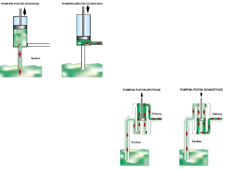
Pumps • Positive displacement: – The liquid is sucked and then it is actually pushed or displaced due to the thrust exerted on it by a moving member, which results in lifting the liquid to the required height. – These pumps usually have one or more chambers which are alternatively filled with liquid to be pumped and then emptied again. – Reciprocating pump.
Positive Displacement- Pumps
Reciprocating Pump- Classification • According to the liquid being in contact with the one side or both the sides of the piston or plunger. – Single acting pump • Has one suction & one delivery pipe and in complete revolution of crank there are only two stroke – 1 suction & 1 delivery stroke. – Double acting pump • Has two suction & two delivery pipe with appropriate valves, so that during each stroke when suction takes place on one side of the piston, the other side delivers the liquid. • There are 2 suction & 2 delivery stroke. • According to the number of the cylinders provided.
Reciprocating Pump- Classification • According to the number of the cylinders provided. – Single cylinder pump • May be either single acting or double acting – Double Cylinder pump • Has two single acting cylinders – Triple cylinder pump • Has three single acting cylinders – Duplex double acting pump • In line either two double-acting single cylinder pumps or two double-acting double cylinder pumps – Quintuplex pump • Has five single acting cylinders driven
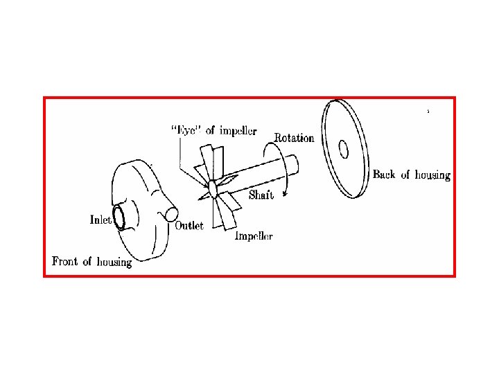
Pumps • Variable head capacity (or) Roto-dynamic (or) dynamicpressure pumps: • Having a rotating element, called impeller, through which as the liquid passes its angular momentum changes, due to which the pressure energy of the liquid is increased. • Doesn’t pus the liquid as in case of a positive displacement pump. • Centrifugal pump • The turbine pump • The rotary pumps • The gear pump • Screw pumps
Centrifugal Pumps • According to the general direction of flow liquid within in the passage of the rotating wheel or impeller, the rotodynamic pumps are classified as, – Centrifugal pump • In the impeller of the centrifugal pump the liquid flows in the outward radial direction. – Axial flow or propeller pumps • In the axial direction, parallel to the rotating shaft. – Half axial or screw or mixed flow pumps • Intermediate form • However, there are no rigid boundaries separating these three types of pumps. • Often all three types of pumps are called centrifugal pumps.
Advantages of Centrifugal pumps over Reciprocating pumps • Discharging capacity is higher • Can be used for lifting highly viscous liquids such as oils, muddy and sewage water, paper pulp, sugar molasses, chemical etc. • Reciprocating pump can handle only pure water or less viscous liquids free from impurities as otherwise its valves may cause frequent trouble. • Can be operated at very high speeds without any danger of separation and cavitations. • It can be coupled directly through flanged coupling to electric motor. • Reciprocating pump can be operated at low speeds only. • Maintenance cost is low only periodic check up is sufficient. • For a Reciprocating pump the maintenance cost is high because the parts such as valves etc. May need frequent replacement.
• Pump, fan, blower, and compressor are terms that do not have precise meaning. Generally pumps move liquids while fans, blowers and compressors add energy to gasses.
Compressors • The compressor functions to increase the pressure of the air to provide conditions favorable for combustion and expansion of the hot gases through the turbine. • Compressors are used to move gases and vapors in situations where large pressure differences are necessary Compressors are classified by the way they work: – Dynamic (centrifugal and axial) or reciprocating. • Dynamic compressors use a set of rotating blades to add velocity and pressure to fluid. They operate at high speeds and are driven by steam or gas turbines or electric motors. They tend to be smaller and lighter for a given service than reciprocating machines, and hence have lower costs. • Reciprocating compressors use pistons to push gas to a higher pressure. They are common in natural gas gathering and transmission systems, but are less common in process applications. Reciprocating compressors may be used when very large pressure differences must be achieved.
Compressors • Five most common types – Reciprocating • Uses a piston-cylinder and valves • Most common type of compressor – Screw • Lobes of two rotating screws trap and compress gas – Centrifugal • Uses centrifugal force to compress gas • Common in large refrigeration systems – Vane • Uses a roller to compress gas • Used in most domestic refrigeration and ac systems
Compressors • The compression ratio, pout over pin, is a key parameter in understanding compressors and blowers. When the compression ratio is below 4 or so, a blower is usually adequate. Higher ratios require a compressor, or multiple compressor stages, be used. • When the pressure of a gas is increased in an adiabatic system, the temperature of the fluid must rise. • Since the temperature change is accompanied by a change in the specific volume, the work necessary to compress a unit of fluid also changes. • Consequently, many compressors must be accompanied by cooling to reduce the consequences of the adiabatic temperature rise. • The coolant may flow through a jacket which surrounds the housing with liquid coolant. When multiple stage compressors are used, intercooler heat exchangers are often used between the stages.
Centrifugal Compressors • This type of compressor consists of an impeller or impellers rotating at high speed within a casing. Flow is continuous and inlet and discharge valves are not required as part of the compression machinery. • Block valves are required for isolation during maintenance. • Centrifugal compressors are widely used in the petroleum, gas, and the chemical industries primarily due to the large volumes of gas that frequently have to be handled. • Long continuous operating periods without an repair make centrifugal compressors desirable for use for petroleum refining and natural gas applications. • The main disadvantage of this type compressor is that it is very sensitive to gas density, molecular weight and polytropic compression exponent. • A decrease in density or molecular weight results in an increase in the polytropic head requirement of the compressor to develop the required compression ratio.
Reciprocating Compressors • Reciprocating compressors are widely used in the petroleum and chemical industries. • They consist of pistons moving in cylinders with inlet and exhaust valves. • They are cheaper and more efficient than any other type in the fields in which they are used. • Their main advantages are that they are insensitive to gas characteristics and they can handle intermittent loads efficiently. • Reciprocating compressors are used almost exclusively in services where the discharge pressures are above 5, 000 psig. • When compared with centrifugal compressors, the reciprocating compressors require frequent shutdowns for maintenance of valves and other wearing parts. • For critical services this requires either a spare compressor or a multiple compressor installation to maintain plant throughput.
Rotary Screw Compressors • • Lobes of two rotating screws trap and compress gas
Vane Compressors • Uses a roller to compress gas